WO2017145356A1 - Detection device, detection system, detection method, information processing device, and processing program - Google Patents
Detection device, detection system, detection method, information processing device, and processing program Download PDFInfo
- Publication number
- WO2017145356A1 WO2017145356A1 PCT/JP2016/055809 JP2016055809W WO2017145356A1 WO 2017145356 A1 WO2017145356 A1 WO 2017145356A1 JP 2016055809 W JP2016055809 W JP 2016055809W WO 2017145356 A1 WO2017145356 A1 WO 2017145356A1
- Authority
- WO
- WIPO (PCT)
- Prior art keywords
- information
- accuracy
- detection
- calculation unit
- unit
- Prior art date
Links
Images


Classifications
-
- G—PHYSICS
- G01—MEASURING; TESTING
- G01B—MEASURING LENGTH, THICKNESS OR SIMILAR LINEAR DIMENSIONS; MEASURING ANGLES; MEASURING AREAS; MEASURING IRREGULARITIES OF SURFACES OR CONTOURS
- G01B11/00—Measuring arrangements characterised by the use of optical techniques
- G01B11/24—Measuring arrangements characterised by the use of optical techniques for measuring contours or curvatures
-
- G—PHYSICS
- G06—COMPUTING; CALCULATING OR COUNTING
- G06T—IMAGE DATA PROCESSING OR GENERATION, IN GENERAL
- G06T7/00—Image analysis
- G06T7/60—Analysis of geometric attributes
- G06T7/62—Analysis of geometric attributes of area, perimeter, diameter or volume
-
- G—PHYSICS
- G06—COMPUTING; CALCULATING OR COUNTING
- G06T—IMAGE DATA PROCESSING OR GENERATION, IN GENERAL
- G06T7/00—Image analysis
- G06T7/40—Analysis of texture
-
- G—PHYSICS
- G06—COMPUTING; CALCULATING OR COUNTING
- G06T—IMAGE DATA PROCESSING OR GENERATION, IN GENERAL
- G06T7/00—Image analysis
- G06T7/50—Depth or shape recovery
- G06T7/507—Depth or shape recovery from shading
-
- G—PHYSICS
- G06—COMPUTING; CALCULATING OR COUNTING
- G06T—IMAGE DATA PROCESSING OR GENERATION, IN GENERAL
- G06T7/00—Image analysis
- G06T7/50—Depth or shape recovery
- G06T7/521—Depth or shape recovery from laser ranging, e.g. using interferometry; from the projection of structured light
-
- G—PHYSICS
- G06—COMPUTING; CALCULATING OR COUNTING
- G06T—IMAGE DATA PROCESSING OR GENERATION, IN GENERAL
- G06T7/00—Image analysis
- G06T7/70—Determining position or orientation of objects or cameras
-
- G—PHYSICS
- G06—COMPUTING; CALCULATING OR COUNTING
- G06T—IMAGE DATA PROCESSING OR GENERATION, IN GENERAL
- G06T2207/00—Indexing scheme for image analysis or image enhancement
- G06T2207/10—Image acquisition modality
- G06T2207/10028—Range image; Depth image; 3D point clouds
Definitions
- the present invention relates to a detection device, a detection method, an information processing device, and a processing program.
- a technique has been proposed in which a target object is detected by a plurality of imaging devices, a plurality of obtained images are input to a computer, and a three-dimensional shape of the target object is acquired (see, for example, Patent Document 1).
- the three-dimensional shape of the object can be constructed with high accuracy from the result of detecting the object.
- a detection unit that detects an object from one viewpoint, a accuracy calculation unit that calculates accuracy information of the object at one viewpoint using a detection result of the detection unit, and a detection unit
- a detection device includes an information calculation unit that calculates at least one of shape information and texture information of an object at one viewpoint using detection results and accuracy information.
- the apparatus includes a plurality of detection devices according to the first aspect and an information processing device that processes information output from the plurality of detection devices.
- Model information including at least one of shape information and texture information is output, and the information processing apparatus is provided with a detection system including a model integration unit that integrates model information.
- a detection system including the detection apparatus according to the first aspect and an information processing apparatus that processes information output from the detection apparatus.
- the detection unit detects the object from one viewpoint, calculates the accuracy information of the object at one viewpoint using the detection result of the detection unit,
- a detection method including calculating at least one of shape information and texture information of an object at one viewpoint using a detection result and accuracy information is provided.
- the first model information including at least one of the shape information and the texture information of the object at one viewpoint calculated using the first detection result and the first accuracy information
- a receiving unit for receiving second model information including at least one of shape information and texture information of an object at a viewpoint different from the one viewpoint, calculated using the second detection result and the second accuracy information
- an information processing apparatus including a model integration unit that integrates first model information and second model information.
- a processing program for processing a detection result obtained by detecting an object from one viewpoint by a detection unit uses the detection result of the detection unit to detect the object at one viewpoint.
- a processing program that calculates accuracy information and calculates at least one of shape information and texture information of an object from one viewpoint using detection results and accuracy information of a detection unit.
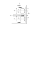
- FIG. 1A is a conceptual diagram illustrating an example of the detection apparatus 1 according to the present embodiment.
- the detection device 1 is, for example, an imaging device, and detects an object OB in a detection region A1 (eg, visual field).
- the detection device 1 may be, for example, a fixed point camera, a camera whose view can be changed manually or automatically, or a portable information terminal (for example, a smartphone, a tablet, a camera-equipped mobile phone).
- the detection device 1 performs calculation processing of information related to the object OB using the result of detecting the object OB.
- the detection apparatus 1 models at least a part of the object OB by calculation processing of the terminal itself, and calculates model information (model data).
- the detection device 1 performs computer graphic processing (CG processing) on at least a part of the object OB by calculation processing, and calculates model information (eg, CG model data).
- the model information includes, for example, at least one of shape information indicating a three-dimensional shape of the object OB and texture information indicating a pattern on the surface of the object OB.
- the model information includes three-dimensional point coordinates, related information of the point coordinates, texture information of the surface defined by the point coordinates and the related information, image space such as illumination conditions and light source information of the entire image. It includes at least one of information and polygon data as shape information.
- the texture information includes, for example, at least one information of characters, figures, patterns, unevenness information on the surface of the object OB, a specific image, and colors (eg, chromatic color, achromatic color).
- the detection apparatus 1 calculates model information indicating the object OB viewed from the viewpoint Vp (eg, a predetermined viewpoint, one viewpoint, a single viewpoint, and one direction).
- the detection apparatus 1 calculates model information indicating the object OB viewed from one viewpoint at a predetermined angle with respect to the object OB.
- FIG. 1B is a block diagram illustrating an example of the configuration of the detection apparatus 1.
- the detection device 1 includes, for example, a detection unit 2, an accuracy calculation unit 3, an information calculation unit 4, a storage unit 5, a communication unit 6, a control unit 7, and a main body unit 8.
- the main body 8 is, for example, a camera body, a case, a housing, or the like.
- the detection unit 2, the accuracy calculation unit 3, and the information calculation unit 4 are provided in the main body unit 8, for example.
- the detection unit 2 detects the object OB from the viewpoint Vp.
- the accuracy calculation unit 3 calculates accuracy information of the object OB at the viewpoint Vp.
- the accuracy calculation unit 3 calculates, for example, accuracy information of the object OB corresponding to the viewpoint Vp.
- the accuracy information includes, for example, at least one of a probability that an object exists at each position in a region including the object OB (eg, the detection region A1 of the detection unit 2 and the visual field), a probability distribution, and an expected value.
- This probability distribution is information indicating the relationship between the accuracy of a part of the detection region of the detection unit 2 and the accuracy of the surrounding region, for example.
- the accuracy information includes, for example, the reliability of the detection result of the detection unit 2 for each position of the region including the object OB (eg, the detection region of the detection unit 2 and the visual field).
- the accuracy is a numerical value of the accuracy (accuracy, accuracy, reliability) or uncertainty (ambiguity, ambiguity) of the data at each location, and the accuracy information is the accuracy at multiple locations. Including the distribution. For example, high accuracy corresponds to high accuracy or low uncertainty. For example, low accuracy corresponds to low accuracy or high uncertainty.
- the detection unit 2 transmits a detection result (for example, image data) that detects the object OB to the information calculation unit 4, and the accuracy calculation unit 3 uses the accuracy information of the calculated object OB to the information calculation unit 4. Send to.
- the information calculation unit 4 calculates at least one of the shape information and the texture information of the object OB at the viewpoint Vp using the received detection result and accuracy information of the detection unit 2. For example, the information calculation unit 4 calculates at least one of shape information and texture information of the object OB when viewed from the viewpoint Vp. For example, the accuracy calculation unit 3 calculates accuracy information for each area of the object OB, and the information calculation unit 4 converts the accuracy information calculated for each area of the object OB into at least one of shape information and texture information. Associate. Hereinafter, each part of the detection apparatus 1 will be described.
- FIG. 2 is a diagram illustrating an example of the detection unit 2.
- the detection unit 2 optically detects the object OB from the viewpoint Vp. For example, at least one of an image of the object OB viewed from one viewpoint (viewpoint Vp) and a distance from one viewpoint (viewpoint Vp) to each point on the object OB is acquired.
- the detection unit 2 may detect the object OB at a predetermined viewing angle.
- the detection unit 2 may detect the object OB with a predetermined line of sight (eg, a single line of sight).
- the detection unit 2 includes, for example, an imaging unit 11 and a distance measurement unit 12.
- the imaging unit 11 images the object OB from the viewpoint Vp and outputs image data of the object OB as a detection result.
- the detection result of the detection unit 2 includes, for example, image data of the detected object OB.
- the distance measuring unit 12 detects the distance from the viewpoint Vp (see FIG. 1A) to each point on the object OB. Note that the detection unit 2 may not include the imaging unit 11 or the distance measurement unit 12.
- the imaging unit 11 includes an imaging optical system 13 and an imaging element 14.
- the imaging optical system 13 forms an image of the object OB.
- the imaging optical system 13 is held in, for example, a lens barrel and attached to the main body 8 (see FIG. 1) together with the lens barrel.
- the imaging optical system 13 and the lens barrel are, for example, interchangeable lenses and can be detached from the main body 8.
- the imaging optical system 13 and the lens barrel may be built-in lenses.
- the lens barrel may be a part of the main body 8 or may not be removable from the main body 8.
- the image sensor 14 is, for example, a CMOS image sensor or a CCD image sensor in which a plurality of pixels are two-dimensionally arranged.
- the image sensor 14 is accommodated in the main body 8, for example.
- the image sensor 14 captures an image formed by the imaging optical system 13.
- the imaging result (detection result) of the imaging device 14 includes, for example, information on the gradation value for each color of each pixel (eg, RGB data).
- the imaging element 14 outputs the imaging result in a data format of a full color image.
- the distance measuring unit 12 detects the distance from each point on the surface of the object OB.
- the distance measuring unit 12 detects the distance by, for example, the TOF (time of flight) method.
- the distance measuring unit 12 may detect the distance by other methods.
- the distance measuring unit 12 may include a laser scanner and detect a distance by laser scanning.
- the distance measuring unit 12 may project a predetermined pattern on the object OB and measure the distance based on the detection result of the pattern.
- the distance measuring unit 12 may include a phase difference sensor and detect a distance by a phase difference method.
- the distance measuring unit 12 may detect the distance by a DFD (depth from defocus) method. When the DFD method is used, the distance measuring unit 12 may use at least one of the imaging optical system 13 and the imaging element 14 of the imaging unit 11.
- the distance measuring unit 12 includes, for example, an irradiation unit 15, an imaging optical system 16, an image sensor 17, and a controller 18.
- the irradiation unit 15 can irradiate the object OB with infrared light.
- the irradiation unit 15 is controlled by the controller 18.
- the controller 18 changes the intensity of the infrared light irradiated from the irradiation unit 15 with time (for example, amplitude modulation).
- the imaging optical system 16 forms an image of the object OB.
- the imaging optical system 16 may be at least a part of an interchangeable lens, or may be at least a part of a built-in lens.
- the image sensor 17 is, for example, a CMOS image sensor or a CCD image sensor.
- the image sensor 17 has sensitivity at least in the wavelength band of light irradiated by the irradiation unit 15.
- the image sensor 17 is controlled by the controller 18 and detects infrared light reflected and scattered by the object OB.
- the image sensor 17 captures an image formed by the imaging optical system 16.
- the controller 18 detects the distance (depth) from each point on the surface of the object OB to the image sensor 17 using the detection result by the image sensor 17. For example, the flight time of light incident on the image sensor 17 from a point on the surface of the object OB changes according to the depth of this point. The output of the image sensor 17 changes according to the flight time, and the controller 18 calculates the depth based on the output of the image sensor 17, for example. For example, the controller 18 calculates the depth for each partial region (eg, one pixel, a plurality of pixels) of the image captured by the image sensor 17, and calculates the depth information by associating the position of the region with the depth. (Generate).
- partial region eg, one pixel, a plurality of pixels
- the depth information includes, for example, information that associates the position of a point on the surface of the object OB and the distance (depth, depth) from this point to the detection device 1.
- the depth information includes, for example, information (eg, depth image) indicating a depth distribution (eg, depth map) in the object OB.
- the accuracy calculation unit 3 calculates accuracy information based on, for example, optical characteristics of an optical system (eg, the imaging optical system 13 and the imaging optical system 16) provided in the detection unit 2. To do.
- FIG. 3 is an explanatory diagram of the accuracy information based on the optical characteristics of the detection unit 2.
- FIG. 3A is a conceptual diagram illustrating an example of a captured image Im1 obtained by the imaging unit 11.
- the imaging optical system 13 see FIG. 2
- the aberration increases as the distance from the optical axis 13a increases.
- the optical axis 13a of the imaging optical system 13 corresponds to the visual field center 14a of the imaging unit 11, and the imaging unit 11 is a region (eg, one pixel, a plurality of pixels) away from the visual field center 14a in the imaging element 14.
- the symbol Imc is a position on the captured image Im1 corresponding to the center of the visual field of the imaging unit 11.
- the captured image Im1 for example, is more affected by aberrations as it moves away from the position Imc, and the reproducibility of the subject (reliability of the detection result) decreases due to blur or the like.
- the accuracy calculation unit 3 calculates accuracy information based on the distance from the position Imc for each region (eg, one pixel, multiple pixels) of the captured image Im1, for example.
- FIG. 3B is a conceptual diagram illustrating an example of the accuracy according to the distance from the center of the field of view (position Imc) of the imaging unit 11 on the captured image Im1.
- the vertical axis represents the accuracy P1
- the horizontal axis represents the position on the captured image Im1.
- the accuracy P1 has a maximum at the position Imc and decreases as the distance from the position Imc increases.
- the relationship between the accuracy P1 and the distance from the center of the visual field of the imaging unit 11 is determined based on, for example, the distribution of aberrations on the imaging element 14 by the imaging optical system 13.
- the accuracy P1 changes nonlinearly with respect to the distance from the position Imc.
- the accuracy P1 may change linearly with respect to the distance from the position Imc, or change discontinuously (eg, stepwise). May be.
- first relationship information Information indicating the relationship between the accuracy P1 and the distance from the center of the field of view of the imaging unit 11 on the captured image Im1 (hereinafter referred to as first relationship information) is stored in advance in the storage unit 5 (see FIG. 1), for example. .
- the accuracy calculation unit 3 calculates the distance from the position Imc for each region (eg, one pixel, multiple pixels) of the captured image Im1, for example.
- the accuracy calculation unit 3 compares the calculated distance with the first relation information, and calculates the accuracy P1 in this region. For example, the accuracy calculation unit 3 calculates, as the accuracy information, information that associates the position of each region with the accuracy P1 (hereinafter referred to as accuracy P1 information).
- the accuracy calculation unit 3 may calculate accuracy information based on the aberration (eg, aberration distribution) of the imaging optical system 13. Further, the accuracy calculation unit 3 may calculate the accuracy information based on the aberration of the imaging optical system 13 and the distance from the center of the visual field. The accuracy calculation unit 3 calculates accuracy information based on at least one of the distance from the center of the visual field of the distance measurement unit 12 and the aberration of the imaging optical system 16 with respect to the detection result of the distance measurement unit 12. May be.
- the brightness of the captured image Im1 may be saturated in a part of the region due to, for example, reflected light from the object OB. Further, on the object OB, there may be a dark part when viewed from the viewpoint Vp, for example, when there is a shadow of another object.
- the accuracy calculation unit 3 may calculate accuracy information based on, for example, the brightness (brightness / darkness) in the captured image Im1.
- FIG. 3C is a conceptual diagram illustrating an example of the accuracy P2 according to the brightness in the captured image Im1.
- the vertical axis is the accuracy P2
- the horizontal axis is the brightness (for example, the gradation value of the pixel).
- the brightness is constant when the brightness is within the predetermined range BR, and the accuracy P2 decreases as the brightness decreases (becomes darker) than the range BR, and the brightness increases beyond the range BR ( The accuracy P2 decreases as the brightness increases.
- the relationship between brightness and accuracy is arbitrarily set based on, for example, experiments or simulations.
- the accuracy P2 may change nonlinearly with respect to brightness, may change linearly, or may change discontinuously (eg, stepwise).
- Second relationship information Information indicating the relationship between brightness and accuracy (hereinafter referred to as second relationship information) is stored in advance in, for example, the storage unit 5 (see FIG. 1).
- the accuracy calculation unit 3 compares the brightness (eg, gradation value) for each region (eg, one pixel, multiple pixels) of the captured image with the second relation information, and calculates the accuracy P2 in this region.
- the accuracy calculation unit 3 calculates, for example, information associating the position of each region with the accuracy P2 (hereinafter referred to as accuracy P2 information) as accuracy information.
- At least one of the above-described accuracy P1 information and accuracy P2 information may be stored in the same file as the captured image data.
- the data structure (data format, data format) of this information includes, for example, pixel gradation values (R, G, and B gradation values) and accuracy (eg, at least one of accuracy P1 and accuracy P2).
- R, G, and B gradation values e.g., at least one of accuracy P1 and accuracy P2
- a structure in which and are combined may be used.
- at least one of the information on the accuracy P1 and the information on the accuracy P2 may be stored in a file different from the data of the captured image.
- the data structure of the accuracy P1 information may be a structure in which the accuracy values of the respective pixels are arranged in correspondence with the pixel arrangement of the captured image.
- the accuracy calculation unit 3 may not calculate accuracy information based on the optical characteristics of the optical system (eg, the imaging optical system 13 and the imaging optical system 16) provided in the detection unit 2. For example, the accuracy calculation unit 3 may not calculate at least one of the accuracy P1 and the accuracy P2.
- FIG. 4 is a conceptual diagram illustrating an example of the detection region A1 of the detection device 1 (detection unit 2).
- FIG. 4A shows a conceptual view of the object OB and the detection device 1 as viewed from the X direction (eg, side).
- FIG. 4B shows a conceptual diagram of the object OB and the detection device 1 as viewed from the Z direction (eg, upward).
- the accuracy calculation unit 3 uses, as the accuracy information, a first region (for example, an object viewed from the viewpoint Vp) that can be detected from the viewpoint Vp in an area including the object OB (for example, the detection area A1 of the detection unit 2).
- the detection area A1 is, for example, a visual field of the detection device 1 (eg, the detection unit 2).
- the first area AR1 is, for example, the surface of the object (eg, object OB, background, floor F in FIG. 4A, wall W in FIG. 4B) detected by the detection unit 2 in the detection area A1. And a region between the detection unit 2 and the detection unit 2.
- symbol OBx is an arbitrary point on the surface of the object (for example, a target object) detected by the detection unit 2.
- the position of the point OBx is represented by, for example, three-dimensional coordinates based on the viewpoint Vp, and is obtained from shape information (eg, point group data and surface information described later) calculated by the information calculation unit 4.
- the accuracy calculation unit 3 sets the area ARa between the viewpoint Vp and the point OBx as the first area AR1.
- the area ARa is an area where the existence probability of an object that blocks light on a line connecting the viewpoint Vp and the point OBx is low, for example.
- the first area AR1 is, for example, a set of areas ARa for each of the plurality of points OBx.
- the first area AR1 is a gap (gas space).
- the accuracy calculation unit 3 calculates coordinates indicating the range of the first area AR1 based on the shape information calculated by the information calculation unit 4.
- the accuracy calculation unit 3 has, as accuracy information, coordinates indicating the first area AR1 and a low probability that an object that blocks light exists in the first area AR1 (an object that blocks light in the first area AR1 exists). Information that is associated with the accuracy indicating that there is a high probability of not).
- the accuracy calculation unit 3 determines, for example, an area ARb farther than the point OBx from the viewpoint Vp as the second area AR2 on the line connecting the viewpoint Vp and the point OBx on the object OB.
- the second area AR2 is, for example, a set of areas ARb for each of the plurality of points OBx.
- the second area AR2 is an area in which the reliability of the detection result of the detection unit 2 is lower than that of the first area AR1.
- the portion of the point OBx is glass or the like, the reliability of the detection result of the detection unit 2 regarding the second region AR2 is increased due to refraction, reflection, scattering, and the like of light from the second region AR2 toward the viewpoint Vp at the point OBx. May decrease.
- the accuracy calculation unit 3 may calculate information indicating that the second area AR2 is an area that cannot be detected from the viewpoint Vp as the accuracy information.
- the accuracy calculation unit 3 may calculate information about the area around the object OB (eg, accuracy information regarding the first area AR1 and accuracy information regarding the second area AR2). In addition, the accuracy calculation unit 3 may calculate information on a space (eg, a gap) on the side of the object OB with respect to the viewpoint Vp.
- a symbol SPx in FIG. 4B is a point in the space on the side of the object OB.
- the distance between the point SPx and the viewpoint Vp is, for example, the same as the distance between the viewpoint Vp and the point OBx.
- the accuracy calculation unit 3 determines whether or not the point SPx belongs to the first area AR1 (area closer to the viewpoint Vp than the surface of the object).
- the accuracy calculation unit 3 determines that there is a gap at the position of the point SPx, for example. In this way, the accuracy calculation unit 3 may detect, for example, a gap on the side of the object OB. In addition, the accuracy calculation unit 3 calculates, for example, information indicating the position of the detected air gap and the probability that the air gap exists at this position (the probability that an object that blocks light is present is low) as the accuracy information. May be. The accuracy calculation unit 3 may not calculate at least a part of the accuracy information described with reference to FIG.
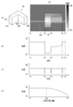
- FIG. 5 is an explanatory diagram of the accuracy information based on the distance detected by the distance measuring unit 12.
- FIG. 5A is a conceptual diagram illustrating an example of depth information (depth image Im2).
- the object OB is represented by a dotted line, and the distance for each region (for example, one pixel or a plurality of pixels of the depth image Im2) included in the detection region A1 of the detection unit 2 is represented in grayscale.
- the depth image Im2 a portion with a high gradation value (close to white) is close to the viewpoint Vp, and a portion with a low gradation value (close to black) is far from the viewpoint.
- FIG. 5B is a diagram illustrating an example of the relationship between the distance and the accuracy P3.
- the distance measurement unit 12 may have a lower reliability (eg, detection accuracy) of a detection result as the position is farther from the viewpoint Vp.
- the accuracy calculation unit 3 calculates, for example, the accuracy P3 of a value having a negative correlation with the distance as accuracy information.
- the accuracy P3 decreases as the distance from the viewpoint Vp increases.
- Information indicating the relationship between the accuracy P3 and the distance from the viewpoint Vp (hereinafter, third relationship information) is stored in advance in the storage unit 5 (see FIG. 1), for example.
- the accuracy calculation unit 3 collates the distance to the viewpoint Vp in the region with the third relation information for each region (eg, one pixel, a plurality of pixels) on the depth image Im2 (see FIG. 5A). Then, the accuracy P3 of this area is calculated.
- the accuracy calculation unit 3 calculates, for example, information associating the position of each region with the accuracy P3 (hereinafter referred to as accuracy P3 information) as accuracy information.
- FIG. 5C is a diagram showing another example of the relationship between the distance and the accuracy P3.
- the distance measurement unit 12 has, for example, a predetermined distance measurement range (range measurement range), and the reliability (eg, detection accuracy) of the detection result may decrease as the distance from the center of the distance measurement range increases.
- the accuracy calculation unit 3 may calculate the accuracy information as accuracy information based on a deviation amount between the center of the distance measurement range and the distance from the viewpoint.
- the accuracy P3 becomes maximum at the center of the distance measurement range, and decreases as the distance deviates from the center of the distance measurement range.
- the relationship between the distance and the accuracy P3 is appropriately set according to the characteristics of the distance measuring unit 12, for example.
- FIG. 6 is an explanatory diagram of accuracy information based on the distribution of distances.
- FIG. 6A is a conceptual diagram illustrating an example of depth information (depth image Im2) and an object OB.
- symbols X1 to X5 indicate positions in one direction on the depth image Im2.
- the position X1 is the position of one end of the depth image Im2
- the position X2 is the position of the other end of the depth image Im2.
- the section from the position X1 to the position X3 is a portion of the background of the object OB (for example, the floor F and the wall W in FIG. 4).
- a section from the position X3 to the position X4 is a portion of the front surface OB1 of the object OB.
- a section from the position X4 to the position X5 is a portion of the surface OB2 having a step with the front surface OB1.
- a section between the position X5 and the position X2 is a portion of the background of the object OB (for example, the floor F and the wall W in FIG. 4).
- the position X3 is a portion of the side surface OB3 with respect to the front surface OB1
- the position X4 is a portion of the side surface OB4 between the front surface OB1 and the surface OB2.
- the position X5 is a portion of the side surface OB5 with respect to the surface OB2.
- the side surface OB3, the side surface OB4, and the side surface OB5 are, for example, surfaces that are nearly parallel to the line of sight from the viewpoint Vp, and the reliability of the detection result may be low.
- FIG. 6B is a conceptual diagram showing the distribution of distances on the line Imd in FIG.
- the distance from the viewpoint Vp changes stepwise at each of the position X3, the position X4, and the position X5.
- the reliability of the detection result of the distance measuring unit 12 decreases, for example, at a position where the amount of change in distance is greater than a threshold (eg, near a step).
- the accuracy calculation unit 3 may calculate the accuracy according to the amount of change in distance as the accuracy information.
- the accuracy calculation unit 3 may calculate the accuracy of a negative correlation value with respect to the distance change amount as the accuracy information.
- the accuracy calculation unit 3 may calculate the accuracy indicating that the reliability of the detection result of the distance measurement unit 12 is high for an area where the change amount of the distance is relatively small. Further, for example, the accuracy calculation unit 3 may calculate the accuracy indicating that the reliability of the detection result of the distance measurement unit 12 is low for an area where the change amount of the distance is relatively large.
- FIG. 6C is a conceptual diagram showing an example of the distribution of the accuracy P4 based on the distance change amount.
- the amount of change in distance is, for example, an amount corresponding to the inclination between the line of sight passing through the viewpoint of the detection unit 2 and the surface on the object OB.
- the accuracy P4 is relatively low at a position where the distance change amount is large (eg, position X3, X4, position X5).
- the accuracy calculation unit 3 calculates the amount of change in distance (for example, the difference between the depths of two adjacent regions) for each region of the depth image Im2, and compares the calculated amount of change with a threshold value. For example, when the amount of change in distance is equal to or less than a threshold, the accuracy calculation unit 3 sets the accuracy P4 of this region to a high level. The accuracy calculation unit 3 sets the accuracy P4 of this region to a low level when the amount of change in distance is greater than the threshold.
- the amount of change in distance for example, the difference between the depths of two adjacent regions
- FIG. 6D is a conceptual diagram showing an example of the relationship between the distance change amount and the accuracy P4.
- the accuracy P4 is constant in the range where the distance change amount is equal to or less than the threshold value Dth, and decreases in the range where the distance change amount exceeds the threshold value Dth.
- the accuracy P4 may change nonlinearly with respect to the amount of change in distance, may change linearly, or may change discontinuously (eg, stepwise).
- Information indicating the relationship between the accuracy P4 and the amount of change in the distance from the viewpoint Vp (hereinafter referred to as fourth relationship information) is stored in advance in the storage unit 5 (see FIG. 1), for example.
- the accuracy calculation unit 3 calculates a change amount of the distance to the viewpoint Vp for each region (eg, one pixel, a plurality of pixels) on the depth image Im2 (see FIG. 6A), and calculates the change amount.
- the accuracy P4 of each region is calculated by collating with the fourth relation information.
- the accuracy calculation unit 3 calculates, for example, information associating the position of each region with the accuracy P4 (hereinafter referred to as accuracy P4 information) as accuracy information.
- At least one of the information on the accuracy P3 and the information on the accuracy P4 may be stored in the same file as the depth information.
- the data structure (data format, data format) of this information may be, for example, a structure in which accuracy (at least one of accuracy P3 and accuracy P4) and depth are combined for each partial region of the detection region A1.
- this information may be expressed in a format in which the depth value and the accuracy are paired for each region (for example, one pixel, a plurality of pixels) of the depth image Im2.
- at least one of the accuracy P3 information and the accuracy P4 information may be stored in a file different from the depth information.
- At least one of the data structure of the information of accuracy P1 and the data structure of the information of accuracy P2 may be a structure in which the accuracy values of the respective regions are arranged in correspondence with the data array of the distances of the respective regions in the depth information.
- the accuracy calculation unit 3 may not calculate at least one of the information on the accuracy P3 and the information on the accuracy P4. Further, the accuracy calculation unit 3 may not calculate accuracy information based on the distance detected by the detection unit 2 (eg, the distance measurement unit 12).
- the accuracy calculation unit 3 may calculate the accuracy by combining two or more of the accuracy P1 to the accuracy P4. For example, the accuracy calculation unit 3 may calculate the accuracy by performing weighting (calculation of weighted average) using two or more of the accuracy P1 to the accuracy P4. Further, the accuracy calculation unit 3 may calculate at least one of an arithmetic average and a geometric average of two or more of the accuracy P1 to the accuracy P4 as the accuracy.
- the information calculation unit 4 includes, for example, a digital signal processor (DSP).
- DSP digital signal processor
- the information calculation unit 4 calculates at least one of the shape information and texture information of the object OB using the detection result (eg, depth information) of the detection unit 2.
- the distance measurement unit 12 generates depth information.
- the information calculation unit 4 may generate depth information based on the depth detected by the distance measurement unit 12. Further, the information calculation unit 4 may generate information in which the accuracy information calculated by the accuracy calculation unit 3 based on the depth information is associated with the depth information.
- the information calculation unit 4 calculates, for example, point group data including coordinates of a plurality of points on the object OB based on the detection result of the detection unit 2 as shape information.
- the information calculation unit 4 calculates point cloud data using the detection result (eg, depth information) of the distance measuring unit 12 (point cloud data processing). For example, the information calculation unit 4 calculates the point cloud data by perspective conversion from a distance image (depth image) indicated by the depth information to a flat image. Note that when the field of view is different between the imaging unit 11 and the distance measurement unit 12, the information calculation unit 4 uses the detection result of the distance measurement unit 12 from the field of view of the imaging unit 11 by perspective transformation (projection transformation), for example. You may convert into the result of having detected OB.
- the information calculation unit 4 may perform the perspective transformation using a parameter that depends on the positional relationship between the field of view of the imaging unit 11 and the field of view of the distance measurement unit 12 (eg, the position of the viewpoint, the direction of the line of sight). Good.
- the information calculation unit 4 generates point cloud data using accuracy information, for example.
- the information calculation unit 4 may select a region having a relatively high accuracy in the depth image and perform perspective conversion from the depth image to the flat image.
- the information calculation unit 4 may omit the perspective transformation of at least a part of a region having a relatively low accuracy in the depth image.
- the information calculation unit 4 may generate the point cloud data without using information with relatively low accuracy among the depth information. In this case, the information calculation unit 4 reduces the processing load, and generates the point cloud data. The amount of data can be reduced.
- the information calculation unit 4 may perform a perspective conversion from a depth image to a planar image by interpolating a region having a relatively low accuracy using a region having a relatively high accuracy in the depth image.
- the information calculation unit 4 stores the calculated point cloud data in the storage unit 5, for example.
- the information calculation unit 4 generates information that associates point cloud data and accuracy information.
- the information calculation unit 4 calculates information in which three-dimensional point coordinates included in the point cloud data are associated with the accuracy of the point on the depth image corresponding to this point.
- the data structure of this information may be, for example, a structure in which three-dimensional point coordinates and accuracy are paired.
- the information calculation unit 4 causes the storage unit 5 to store information in which the point cloud data and the accuracy information are associated with each other.
- the information calculation unit 4 may generate point cloud data without using the accuracy information. Further, the accuracy calculation unit 3 may calculate accuracy information (accuracy information of the point cloud data) regarding the information of the points included in the point cloud data using the point cloud data generated by the information calculation unit 4. For example, the accuracy calculation unit 3 may calculate the accuracy information based on distance information between two predetermined points included in the point cloud data. For example, the accuracy calculation unit 3 may select two adjacent points from the point cloud data and compare the distance between these two points with a threshold value to calculate accuracy information. In addition, the accuracy calculation unit 3 may calculate the accuracy information based on the spatial frequency information (for example, the density of the spatial distribution of points) of a plurality of points included in the point cloud data.
- the spatial frequency information for example, the density of the spatial distribution of points
- the accuracy calculation unit 3 may calculate the accuracy information based on vector information connecting two points included in the point cloud data. For example, the accuracy calculation unit 3 may select two adjacent points from the point cloud data, and calculate the accuracy information using a vector connecting these two points and the position information of the detection device 1.
- the position information of the detection device 1 includes, for example, the direction of the viewpoint Vp (detection direction, line of sight, and optical axis direction of the optical system).
- the accuracy calculation unit 3 may calculate the accuracy information according to the angle between a vector connecting two points included in the point cloud data and the orientation of the viewpoint Vp.
- the accuracy calculation unit 3 may reduce the accuracy of at least one of the start point and the end point of the vector relatively low. Good. For example, the accuracy calculation unit 3 may relatively increase the accuracy when the angle between the vector and the direction of the viewpoint Vp is close to 90 ° or 270 °.
- the information used by the accuracy calculation unit 3 to calculate accuracy information may be one type or two or more types of the distance information, the spatial frequency information, the vector information, and the position information of the detection device 1.
- the point cloud data used by the accuracy calculation unit 3 to calculate accuracy information may be generated by the information calculation unit 4 using the accuracy information, or may be generated by the information calculation unit 4 without using the accuracy information.
- the accuracy calculation unit 3 may store accuracy information calculated using the point cloud data in the storage unit 5.
- the information calculation unit 4 generates surface information including the coordinates of a plurality of points on the object OB and connection information between the plurality of points based on the detection result of the detection unit 2 as shape information.
- the surface information is, for example, polygon data, vector data, draw data, or the like.
- the connection information includes, for example, information that associates points at both ends of a line corresponding to a ridge line (eg, edge) of the object OB, and information that associates a plurality of lines corresponding to the contour of the surface of the object OB.
- the information calculation unit 4 estimates a surface between a point selected from a plurality of points included in the point cloud data and a nearby point, and converts the point cloud data into polygon data having plane information between the points. Convert (surface processing).
- the information calculation unit 4 converts the point cloud data into polygon data by an algorithm using a least square method, for example. This algorithm may be, for example, an algorithm published in the point cloud processing library.
- the information calculation unit 4 generates surface information using accuracy information, for example. For example, when estimating a surface between a point selected from a plurality of points included in the point cloud data and a nearby point, the information calculation unit 4 selects a nearby point in consideration of accuracy. For example, the information calculation unit 4 selects a point with relatively high accuracy as a nearby point. For example, the information calculation unit 4 may generate the surface information without using information with relatively low accuracy among the point cloud data. In this case, the information calculation unit 4 reduces the processing load, and the generated surface information data. The amount can be reduced. In addition, when the accuracy of the above-described neighboring points is lower than the threshold value, the information calculation unit 4 may perform interpolation using points with relatively high accuracy among the surrounding points.
- the information calculation unit 4 generates information associating surface information and accuracy information, for example.
- the information calculation unit 4 generates information in which information on the line (or surface) included in the surface information is associated with information on the accuracy of the point of the point cloud data corresponding to the line (or surface).
- This information may be stored, for example, as attribute information of elements (eg, lines, surfaces) included in the surface information.
- the information calculation unit 4 causes the storage unit 5 to store information in which surface information and accuracy information are associated with each other.
- the information calculation unit 4 may not use the accuracy information when generating the surface information.
- the information calculation unit 4 does not have to use the accuracy information when generating the point cloud data using the accuracy information and generating the surface information based on the point cloud data.
- the accuracy calculation unit 3 may calculate accuracy information using the surface information generated by the information calculation unit 4.
- the surface information may include information on a line (graph) connecting two points, and the accuracy calculation unit 3 may calculate accuracy information regarding the line information.
- the accuracy calculation unit 3 uses at least one of the distance information, the vector information, and the position information of the detection device 1 to obtain line information. You may calculate the accuracy information regarding.
- the surface information includes, for example, information on the surface of the object surrounded by three or more lines, and the information calculation unit 4 may generate surface information using accuracy information regarding the line information. For example, a line with relatively high accuracy among a plurality of candidates for the outer peripheral line of the surface may be adopted as the outer peripheral line of the surface.
- the surface information may include, for example, surface information surrounded by three or more lines, and the accuracy calculation unit 3 may calculate accuracy information regarding the surface information.
- the accuracy calculation unit 3 may calculate the accuracy information regarding the surface information by an arithmetic average, a geometric average, or a weighted average using the accuracy information regarding the line information corresponding to the outer peripheral line of the surface.
- the accuracy calculation unit 3 may calculate the accuracy information by using the normal direction of the surface and the position information of the detection device 1 (for example, the direction of the viewpoint Vp). For example, the accuracy calculation unit 3 may calculate the accuracy information according to the angle between the normal vector of the surface and the orientation of the viewpoint Vp, for example. For example, the accuracy calculation unit 3 may relatively reduce the accuracy of the surface when the angle between the normal vector of the surface and the direction of the viewpoint Vp is close to 0 ° or 180 °. For example, the accuracy calculation unit 3 may relatively increase the accuracy of the surface when the angle between the normal vector of the surface and the direction of the viewpoint Vp is close to 90 ° or 270 °.
- the accuracy calculation unit 3 may calculate accuracy information regarding the point cloud data using the surface information generated by the information calculation unit 4. For example, the accuracy calculation unit 3 may calculate the accuracy information for the point information used for the surface information based on the distance between the surface and the point. For example, when the distance from the surface among the points belonging to the surface is greater than or equal to a threshold, the accuracy calculation unit 3 may lower the accuracy of this point compared to the case where the distance is less than the threshold. The accuracy calculation unit 3 calculates accuracy information about the point cloud data using the surface information, and recalculates at least a part of the surface information (eg, line information, surface information) using the accuracy information. Good. Further, the accuracy calculation unit 3 may store the accuracy information calculated using the surface information in the storage unit 5.
- the accuracy calculation unit 3 may store the accuracy information calculated using the surface information in the storage unit 5.
- the information calculation unit 4 calculates texture information using, for example, an inverse rendering technique.
- the texture information includes, for example, pattern information indicating a pattern on the surface of the object OB, light source information of light that illuminates the object OB, and optical characteristics (eg, reflectance, scattering rate, transmittance) of the surface of the object OB.
- Information of at least one item of optical characteristic information to be shown is included.
- the light source information includes, for example, at least one item of information among the position of the light source, the direction in which light is emitted from the light source to the object, the wavelength of light emitted from the light source, and the type of light source.
- the information calculation unit 4 calculates the light source information using, for example, a model assuming Lambertian reflection, a model including Albedo estimation, and the like. For example, the information calculation unit 4 estimates a component derived from light diffused by the object OB and a component regularly reflected by the object OB among the pixel values of each pixel of the image captured by the imaging unit 11. In addition, the information calculation unit 4 calculates the direction in which light is incident on the object OB from the light source, using, for example, the estimation result of the component regularly reflected by the object OB and the shape information. For example, the information calculation unit 4 estimates the reflection characteristic of the object OB using the calculated light source information and shape information, and calculates optical characteristic information including a reflection characteristic estimation result. In addition, the information calculation unit 4 calculates pattern information by removing the influence of illumination light from visible light image data using, for example, the calculated light source information and optical characteristic information.
- the accuracy calculation unit 3 may calculate accuracy information related to texture information using, for example, image data that is the basis of texture information. For example, the accuracy calculation unit 3 uses the at least one of the luminance (tone value) of R, G, and B of each pixel included in the image data and the spatial frequency information of the texture calculated from the image data, to determine the accuracy. Information may be calculated. In addition, the accuracy calculation unit 3 includes the characteristics of the optical system (eg, illumination field, aberration) used for acquiring the image data, the optical characteristics of the object (eg, reflectance, transmittance, absorptance), and the target. The accuracy information may be calculated by using at least a part of the information on the light source of light that illuminates the object.
- the optical system eg, illumination field, aberration
- the information calculation unit 4 calculates texture information using accuracy information, for example.
- the information calculation unit 4 may calculate texture information by selectively using a region having a relatively high accuracy among detection results (captured images) of the detection unit 2 (eg, the imaging unit 11). .
- the information calculation unit 4 does not have to use a region having a relatively low accuracy in the captured image by the imaging unit 11 for calculating texture information.
- the information calculation unit 4 reduces the processing load and generates the generated texture. The amount of information data can be reduced.
- the information calculation unit 4 may calculate texture information by interpolating information on a region with a relatively low accuracy using information on a region with a relatively high accuracy.
- the accuracy calculation unit 3 calculates accuracy information, for example, for each region of the object OB (eg, each point of point cloud data, surface information element).
- the accuracy information may include, for example, information weighted on the detection result of the detection unit 2 in order to calculate shape information or texture information.
- the accuracy information may include, for example, information weighted with respect to the detection result of the detection unit 2 or information generated from the detection result as information used for calculation of shape information or texture information.
- the coefficient used for the weighting may be a value corresponding to the accuracy included in the accuracy information acquired before the weighting process.
- the identifier eg, ID, number
- the information calculation unit 4 may generate data obtained by adding the identifier of this point to the accuracy information of each point of the point cloud data. Further, the information calculation unit 4 may generate data in which the identifier (ID, number) of the accuracy information of this point is added to the coordinates of each point of the point cloud data.
- the information calculation unit 4 generates data in which surface information elements (eg, lines, surfaces, mesh areas, voxels) and accuracy information of the elements are paired.
- the information calculation unit 4 generates data in which elements defined in the surface information (eg, point connection information) and accuracy information of the elements are paired.
- the information calculation unit 4 generates data in which texture information calculated for each region of the object OB (for example, one pixel and a plurality of pixels of the captured image) is combined with accuracy information of this region.
- the information calculation unit 4 associates each element of the surface information with the accuracy information by associating the identifier (eg, ID, number) of each element of the surface information with the accuracy information of this element.
- the information calculation unit 4 may generate data obtained by adding the identifier of this element to the accuracy information of the element of the surface information.
- the information calculation unit 4 may generate data obtained by adding the identifier (ID, number) of the accuracy information of this point to the information (eg, point connection information) of the element of the surface information.
- the information calculation unit 4 generates model information in which header information (for example, identification information such as a number or a code) is added to information including at least one of shape information and texture information.
- This header information includes identification information, position of the detection device 1 (position information), imaging timing by the imaging unit 11, imaging time by the imaging unit 11, optical characteristic information of the object OB, and imaging environment information (eg, light source information, At least one of the illumination conditions for the object OB or the like.
- position information position information
- imaging timing by the imaging unit 11 imaging time by the imaging unit 11
- optical characteristic information of the object OB optical characteristic information of the object OB
- imaging environment information eg, light source information, At least one of the illumination conditions for the object OB or the like.
- the information calculation unit 4 generates model information having header information based on a predetermined data format.
- the storage unit 5 is a nonvolatile memory such as a USB memory or a memory card, and stores various types of information.
- the storage unit 5 may include a storage device built in the detection apparatus 1 or may include a port to which a storage device that can be released from the detection apparatus 1 can be connected.
- the control unit 7 controls each unit of the detection device 1 according to a command (control signal) from a user or an external device, for example.
- the control unit 7 causes the detection unit 2 to execute the above detection process.
- This detection processing includes, for example, imaging processing by the imaging unit 11 and distance detection processing by the distance measuring unit 12.
- the control unit 7 causes the storage unit 5 to store at least a part of the detection result of the detection unit 2.
- the control unit 7 causes the accuracy calculation unit 3 to calculate accuracy information.
- at least a part of the accuracy information calculated by the accuracy calculation unit 3 is stored in the storage unit 5.
- the control unit 7 causes the information calculation unit 4 to calculate model information.
- the control unit 7 causes the storage unit 5 to store at least part of the model information calculated by the information calculation unit 4.
- the communication unit 6 includes, for example, at least one of an I / O port such as a USB port and a communication device that performs radio wave or infrared wireless communication.
- the communication unit 6 is controlled by the control unit 7, reads information stored in the storage unit 5, and transmits the read information to an external device.
- the communication unit 6 transfers at least a part of the calculation result (eg, accuracy information) of the accuracy calculation unit 3 and the calculation result (eg, model information) of the information calculation unit 4 to an external device (eg, FIG. 9 later).
- the communication part 6 receives the information containing the instruction
- the communication unit 6 can store the received information in the storage unit 5 and supply the received information to the control unit 7.
- the detection device 1 can output at least a part of the model information to a digital device that can input and output digital information such as a barcode or a two-dimensional code.
- a digital device can display or print digital information including at least a part of the model information on a display or paper.
- a reader device provided with a reader unit (for example, an optical reader) that can read displayed or printed digital information can input the digital information to a storage area of the own device through the reader unit.
- the reader device may further include a rendering processing unit described later.
- the detection system 50 may include a reader device that includes the digital device and the reader unit. Further, the detection device 1 may be configured to include the above-described digital device or reader device.
- the communication unit 6 may transmit at least part of the model information to the above digital device.
- the digital device may generate digital information based on the received model information and output the digital information to a medium such as paper.
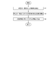
- FIG. 7 is a flowchart illustrating an example of the detection method according to the present embodiment.
- the detection unit 2 detects the object OB from a predetermined one viewpoint (single viewpoint). For example, the imaging unit 11 of the detection unit 2 images the object OB from the viewpoint Vp. Further, for example, the distance measuring unit 12 of the detecting unit 2 detects the distance between the viewpoint Vp and each point on the surface of the object OB.
- the accuracy calculation unit 3 calculates accuracy information of the object OB at a predetermined viewpoint.
- the accuracy calculation unit 3 calculates the accuracy information by using at least a part of the detection result (eg, captured image) of the imaging unit 11 and the detection result (eg, depth information) of the distance measuring unit 12. For example, the accuracy calculation unit 3 calculates at least a part of the accuracy information described with reference to FIGS. In step S ⁇ b> 3, the information calculation unit 4 calculates model information including at least one of the shape information and texture information of the object at the viewpoint Vp using the detection result and the accuracy information of the detection unit 2.
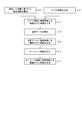
- FIG. 8 is a flowchart showing an example of the processing in steps S2 and S3 in FIG.
- the distance measuring unit 12 detects the depth.
- the accuracy calculation unit 3 calculates accuracy information based on the distance (depth) detected by the distance measurement unit 12, for example, as shown in FIGS.
- the information calculation unit 4 calculates information that associates the accuracy information calculated in step S11 with the depth information generated in step S12.
- the information calculation unit 4 calculates point cloud data using the information calculated in step S13.
- step S15 the information calculation unit 4 generates information that associates the point cloud data and the accuracy information.
- the information calculation unit 4 calculates surface information using the information calculated in step S15.
- the information calculation unit 4 calculates information in which the surface information and the accuracy information are associated with each other.
- FIG. 9 is a flowchart showing another example of the processing in steps S2 and S3 in FIG. 9, the same processes as those in FIG. 8 are denoted by the same reference numerals, and the description thereof is omitted or simplified as appropriate.
- the detection device 1 eg, the controller 18
- the information calculation unit 4 calculates point cloud data.
- the accuracy calculation unit 3 generates accuracy information of the point cloud data calculated by the information calculation unit 4 in step S14.
- the accuracy calculation unit 3 stores the accuracy information of the generated point cloud data in the storage unit 5, for example.
- the information calculation unit 4 calculates line information in the surface information using the point cloud data and the accuracy information of the point cloud data generated by the accuracy calculation unit 3 in step S21.
- the accuracy calculation unit 3 generates accuracy information of the line information calculated by the information calculation unit 4 in step S22.
- the accuracy calculation unit 3 stores, for example, the accuracy information of the generated line information in the storage unit 5.
- step S24 the information calculation unit 4 calculates surface information in the surface information using the line information and the accuracy information of the line information generated by the accuracy calculation unit 3 in step S23.
- the accuracy calculation unit 3 generates accuracy information of the surface information calculated by the information calculation unit 4 in step S24.
- the accuracy calculation unit 3 stores, for example, the accuracy information of the generated surface information in the storage unit 5.
- step S26 the accuracy calculation unit 3 calculates the accuracy information of the point cloud data using the surface information calculated by the information calculation unit 4 in step S24.
- the accuracy calculation unit 3 may update the accuracy information of the point cloud data generated in step S21 to the accuracy information of the point cloud data generated in step S26. Further, the accuracy calculation unit 3 integrates the accuracy information of the point cloud data generated in step S21 and the accuracy information of the point cloud data generated in step S26 by an arithmetic average, a geometric average, a weighted average, or the like. Also good. Further, the accuracy calculation unit 3 may store the accuracy information of the point cloud data generated in step S26 in the storage unit 5 separately from the accuracy information of the point cloud data generated in step S21.
- step S27 the detection apparatus 1 (for example, the information calculation unit 4) determines whether or not to recalculate the surface information. For example, the information calculation unit 4 performs the determination process in step S27 according to setting information that determines in advance whether or not to recalculate.
- the information calculation unit 4 determines to recalculate the surface information (step S27; Yes)
- the information calculation unit 4 returns to step S22, and uses at least a part of the accuracy information generated in the process from the previous step S22 to step S26.
- the processes after step S22 are repeated.
- step S27; No the information calculation unit 4 ends the series of processes.
- the accuracy calculation unit 3 generates accuracy information for point cloud data in step S21, generates accuracy information for line information in step S23, generates accuracy information for surface information in step S25, and in step S26. It is not necessary to perform at least one generation process of the point cloud data accuracy information generation process.
- the information calculation unit 4 may generate at least a part of the surface information (eg, line information, surface information) without using the accuracy information of the items for which the above generation processing has not been performed. . Further, the information calculation unit 4 may generate the surface information (eg, line information, surface information) without using the accuracy information of the item for which the above generation process has been performed.
- the accuracy information on which the above generation process has been performed may be used for a process other than the surface information calculation process, for example, a process using surface information (eg, a rendering process). Further, the information calculation unit 4 does not have to perform the process of step S27, and does not have to recalculate the surface information using at least a part of the accuracy information.
- the detection device 1 includes, for example, a computer (eg, a microcomputer).
- This computer reads a processing program stored in the storage unit 5 and executes various processes according to the processing program.
- This processing program processes, for example, a detection result obtained by optically detecting the object OB from a predetermined one viewpoint (eg, viewpoint Vp) by the detection unit 2.
- This processing program for example, calculates the accuracy information of the object OB at a predetermined one viewpoint (eg, viewpoint) Vp and uses the detection result and the accuracy information of the detection unit 2 to calculate a predetermined one viewpoint.
- This processing program may be provided by being recorded on a computer-readable storage medium.
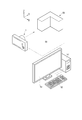
- FIG. 10 is a diagram illustrating an example of the detection system 50 according to the present embodiment.
- the detection system 50 includes a detection device 1 and an information processing device 51 that processes information output from the detection device 1.
- the information processing device 51 is provided with, for example, an input device 52 and a display device 53.
- the information processing device 51 acquires information from the detection device 1 through communication with the detection device 1. For example, the information processing device 51 executes rendering processing using information (eg, model information, accuracy information) acquired from the detection device 1. For example, based on the viewpoint setting information input to the input device 52 by the user, the information processing apparatus 51 calculates estimated image data of the object OB viewed from this viewpoint. For example, the information processing device 51 supplies estimated image data to the display device 53 and causes the display device 53 to display the estimated image.
- information eg, model information, accuracy information
- the input device 52 includes, for example, at least one of a sensor such as a keyboard, a mouse, a touch panel, and an acceleration sensor, a voice input device, and a touch pen.
- the input device 52 is connected to the information processing device 51.
- the input device 52 receives input of information from a user, for example, and supplies the input information to the information processing device 51.
- the display device 53 includes, for example, a liquid crystal display or a touch panel display, and is connected to the information processing device 51.
- the display device 53 displays an image (eg, an estimated image by rendering processing) based on the image data supplied from the information processing device 51.
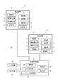
- FIG. 11 is a block diagram illustrating an example of the detection system 50 according to the present embodiment.
- the information processing apparatus 51 includes a communication unit 55, a storage unit 56, a rendering processing unit 57, and a control unit 58.
- the communication unit 55 includes, for example, at least one of a USB port, a network card, and a communication device that performs radio wave or infrared wireless communication.
- the communication unit 55 can communicate with the communication unit 6 of the detection device 1.
- the storage unit 56 includes, for example, a removable storage medium such as a USB memory, and a large-capacity storage device such as an external or built-in hard disk.
- the storage unit 56 stores, for example, at least a part of data received through the communication unit 55, an imaging control program for controlling the detection device 1, a processing program for executing each process of the information processing device 51, and the like. .
- the rendering processing unit 57 includes, for example, a graphics processing unit (Graphics Processing Unit; GPU).
- the rendering processing unit 57 may be configured such that the CPU and the memory execute each process according to the image processing program.
- the rendering processing unit 57 performs at least one of drawing processing, texture mapping processing, and shading processing.
- the rendering processing unit 57 can calculate an estimated image (eg, a reconstructed image) obtained by viewing the shape defined in the shape information of the model information from an arbitrary viewpoint, for example.
- the shape indicated by the shape information is referred to as a model shape.
- the rendering processing unit 57 can reconstruct a model shape (eg, estimated image) from model information (eg, shape information) by, for example, a drawing process.
- the rendering processing unit 57 stores the calculated estimated image data in the storage unit 56.
- the rendering processing unit 57 can calculate an estimated image in which an image indicated by the texture information of the model information is pasted on the surface of an object on the estimated image, for example.
- the rendering processing unit 57 can also calculate an estimated image in which a texture different from the object OB is pasted on the surface of the object on the estimated image. In the shading process, for example, the rendering processing unit 57 can calculate an estimated image in which a shadow formed by the light source indicated by the light source information of the model information is added to the object on the estimated image. In the shading process, the rendering processing unit 57 can calculate an estimated image obtained by adding a shadow formed by an arbitrary light source to an object on the estimated image, for example.
- the rendering processing unit 57 performs a rendering process using, for example, the accuracy information generated by the detection device 1.
- the rendering processing unit 57 may set the resolution of a region having a relatively high accuracy in the model shape to be higher than the resolution of a region having a relatively low accuracy.
- the rendering processing unit 57 may generate an estimated image by reducing (eg, blurring) the resolution of a region having a relatively low accuracy in the model shape.
- the rendering processing unit 57 may omit or simplify the rendering processing of a region having a relatively low accuracy in the model shape.
- the rendering processing unit 57 may perform rendering processing by interpolating a region having a relatively low accuracy among the model shapes using a region having a relatively high accuracy.
- the control unit 58 controls, for example, each unit of the information processing device 51, the detection device 1, the input device 52, and the display device 53.
- the control unit 58 controls the communication unit 55 to cause the detection device 1 to transmit a command (control signal) and setting information.
- the control unit 58 causes the storage unit 56 to store information received from the detection device 1 by the communication unit 55.
- the control unit 58 controls the rendering processing unit 57 to execute rendering processing.
- the detection system 50 may not include the input device 52.
- the detection system 50 may be configured such that various commands and information are input via the communication unit 6.
- the detection system 50 may not include the display device 53.
- the detection system 50 may output estimated image data generated by the rendering process to an external display device, and the display device may display the estimated image.
- FIG. 12 is a diagram showing a detection system 50 according to the present embodiment.
- the detection system 50 includes a plurality of detection devices (first detection device 1a and second detection device 1b) and an information processing device 51 that processes information output from the plurality of imaging devices.
- the information processing device 51 receives information (eg, model information, accuracy information) from the first detection device 1a disposed at the position of the first viewpoint with respect to the object OB through communication with the first detection device 1a. get.
- the information processing device 51 receives information (eg, model information, accuracy information) from the second detection device 1b through communication with the second detection device 1b disposed at the position of the second viewpoint with respect to the object OB. get.
- the information processing device 51 uses the information acquired from the first detection device 1a that detects the object OB from the first viewpoint and the information acquired from the second detection device 1b that detects the object OB from the second viewpoint, Perform information processing.
- each of the first detection device 1a and the second detection device 1b supplies the information processing device 51 with model information representing the object OB viewed from its own viewpoint (one viewpoint, single viewpoint, one direction).
- the information processing apparatus 51 includes first model information representing the object OB viewed from the viewpoint (first viewpoint) of the first detection apparatus 1a and the viewpoint of the second detection apparatus 1b (second viewpoint different from the first viewpoint).
- Model integration processing is performed for integrating the second model information representing the object viewed from the above.
- FIG. 13 is a block diagram showing the detection system 50 according to this embodiment.
- the information processing apparatus 51 includes a receiving unit (communication unit 55).
- the communication unit 55 receives the first model information of the object OB and the second model information of the object OB.
- the first model information includes at least one of shape information and texture information of the object at one viewpoint (eg, viewpoint Vp1 shown in FIG. 14 later).
- the first model information is calculated by the first detection device 1a using, for example, the first detection result by the first detection device 1a and the first accuracy information, and the communication unit 55 receives the first model from the first detection device 1a. Receive information.
- the second model information includes at least one of shape information and texture information of the object at a viewpoint different from the one viewpoint described above (eg, viewpoint Vp2 shown in FIG. 14 later).
- the second model information is calculated by the second detection device 1b using the second detection result by the second detection device 1b and the second accuracy information, and the communication unit 55 receives the second model from the second detection device 1b. Receive information.
- the information processing apparatus 51 includes a model integration unit 59 that performs model integration processing.
- the model integration unit 59 integrates the first model information and the second model information.
- the model integration unit 59 extracts feature points from the shape indicated by the first model information from the first detection device 1a.
- the model integration unit 59 extracts feature points from the shape indicated by the second model information from the second detection device 1b.
- a feature point is a portion that can be distinguished from other portions of the shape indicated by each model information.
- a portion defined for a surface in the surface information can be distinguished from other surfaces by the shape of the outer periphery thereof.
- the model integration unit 59 extracts feature points using at least one of shape information and texture information included in each model information.
- the model integration unit 59 matches feature points between the first model information and the second model information, and detects a feature point common to the first model information and the second model information. Further, the model integration unit 59 uses the feature points common to the first model information and the second model information to determine the relative position and the relative posture between the shape indicated by the first model information and the shape indicated by the second model information. The first model information and the second model information are integrated by calculating.
- the model integration unit 59 uses, for example, at least a part of the accuracy information (first accuracy information) supplied from the first detection device 1a and the accuracy information (second accuracy information) supplied from the second detection device 1b.
- Model integration processing For example, the model integration unit 59 selects information used for integration from the model information based on the accuracy information. For example, when extracting the feature point from the shape indicated by the model information, the model integration unit 59 extracts the feature point from a region having a relatively high accuracy in the shape.
- the model integration unit 59 uses the first accuracy information and the second accuracy information to determine the first part in the overlapping part.
- the accuracy of the one model information is compared with the accuracy of the second model information, and the shape of the overlapping portion is expressed using the model information having a relatively high accuracy.
- the model integration unit 59 may integrate the shape information by weighting (calculating a weighted average) the first model information and the second model information with respect to the overlapping portion.
- the weighted average includes, for example, an arithmetic average, a geometric average, or an exponential average (an exponential weighted moving average).
- the weighting coefficient is determined based on, for example, the accuracy of the first model information in the overlapping portion and the accuracy of the second model information in the overlapping portion.
- FIG. 14 is a conceptual diagram showing an example of model integration processing.
- symbol MF1 is a model shape produced
- symbol MF2 is a model shape produced
- Symbol MF3 is an integrated model shape (integrated model shape).
- the surface Aa, the surface Ba, and the surface Ca have high reliability (accuracy) of the detection result from the viewpoint Vp1.
- the surface Da and the surface Ea have low reliability (accuracy) of the detection result from the viewpoint Vp1.
- the surface Cb, the surface Db, and the surface Eb have reliability (accuracy) of detection results from the viewpoint Vp2. high.
- the surface Ab and the surface Bb have low reliability (accuracy) of detection results from the viewpoint Vp2.
- the model integration unit 59 uses the surface Aa and the surface Ab of the model shape MF1 to generate the model shape MF3, and uses the surface Db and the surface Eb of the model shape MF2 to generate the model shape MF3.
- the model integration unit 59 weights the surface Ca of the model shape MF1 and the surface Cb of the model shape MF2, for example, and uses it for C of the model shape MF3.
- the method in which the model integration unit 59 integrates the first model information and the second model information is not limited to the above example.
- the model integration unit 59 may perform the model integration process using the relative position and relative attitude of the first detection device 1a and the second detection device 1b.
- the model integration unit 59 also determines the relative position between the viewpoint of the first detection device 1a and the viewpoint of the second detection device 1b, the direction (line of sight) of the viewpoint of the first detection device 1a, and the second detection device 1b.
- the model integration process may be performed using the relationship with the viewpoint direction (line of sight).
- the information processing apparatus 51 includes the model integration unit 59 and does not need to include the rendering processing unit 57.
- the information processing apparatus 51 may output the result of the model integration process to an external apparatus, and a rendering processing unit provided in the external apparatus may execute the rendering process.
- the model integration unit 59 may be provided in at least one detection device among a plurality of detection devices (for example, the first detection device 1a and the second detection device 1b).
- the first detection device 1a may include a model integration unit 59.
- the first detection device 1a receives, for example, the second model information from the detection device (second detection device 1b) different from the first detection device 1a by the communication unit 6, and the model integration unit 59
- the first model information calculated by the information calculation unit 4 of the detection apparatus 1a and the second model information may be integrated.
Abstract
[Problem] To provide a detection device that makes it possible to highly accurately construct the three-dimensional shape of an object from detection results for the object. [Solution] A detection device (1) is provided with a detection unit (2) for detecting an object (OB) from one point of view (Vp), an accuracy calculation unit (3) for calculating accuracy information for the object at the viewpoint, and an information calculation unit (4) for calculating at least one from among shape information and texture information for the object at the viewpoint using the detection results of the detection unit and the accuracy information.
Description
本発明は、検出装置、検出方法、情報処理装置、及び処理プログラムに関する。
The present invention relates to a detection device, a detection method, an information processing device, and a processing program.
複数の撮像装置により対象物を検出し、得られた複数の画像をコンピュータに入力し、対象物の三次元形状を取得する技術が提案されている(例えば、特許文献1参照)。
A technique has been proposed in which a target object is detected by a plurality of imaging devices, a plurality of obtained images are input to a computer, and a three-dimensional shape of the target object is acquired (see, for example, Patent Document 1).
上述のような技術においては、対象物を検出した結果から対象物の三次元形状を高精度に構築可能であることが望まれる。
In the technology as described above, it is desired that the three-dimensional shape of the object can be constructed with high accuracy from the result of detecting the object.
本発明の第1の態様に従えば、一視点から対象物を検出する検出部と、検出部の検出結果を用いて一視点における対象物の確度情報を算出する確度算出部と、検出部の検出結果および確度情報を用いて、一視点における対象物の形状情報とテクスチャ情報との少なくとも一方を算出する情報算出部と、を備える検出装置が提供される。
According to the first aspect of the present invention, a detection unit that detects an object from one viewpoint, a accuracy calculation unit that calculates accuracy information of the object at one viewpoint using a detection result of the detection unit, and a detection unit A detection device is provided that includes an information calculation unit that calculates at least one of shape information and texture information of an object at one viewpoint using detection results and accuracy information.
本発明の第2の態様に従えば、第1の態様の複数の検出装置と、複数の検出装置から出力される情報を処理する情報処理装置と、を備え、複数の検出装置は、それぞれ、形状情報とテクスチャ情報の少なくとも一方を含むモデル情報を出力し、情報処理装置は、モデル情報を統合するモデル統合部を含む、検出システムが提供される。
According to a second aspect of the present invention, the apparatus includes a plurality of detection devices according to the first aspect and an information processing device that processes information output from the plurality of detection devices. Model information including at least one of shape information and texture information is output, and the information processing apparatus is provided with a detection system including a model integration unit that integrates model information.
本発明の第3の態様に従えば、第1の態様の検出装置と、検出装置から出力される情報を処理する情報処理装置と、を備える検出システムが提供される。
According to the third aspect of the present invention, there is provided a detection system including the detection apparatus according to the first aspect and an information processing apparatus that processes information output from the detection apparatus.
本発明の第4の態様に従えば、一視点から対象物を検出部により検出することと、検出部の検出結果を用いて一視点における対象物の確度情報を算出することと、検出部の検出結果および確度情報を用いて、一視点における対象物の形状情報とテクスチャ情報との少なくとも一方を算出することと、を含む検出方法が提供される。
According to the fourth aspect of the present invention, the detection unit detects the object from one viewpoint, calculates the accuracy information of the object at one viewpoint using the detection result of the detection unit, A detection method including calculating at least one of shape information and texture information of an object at one viewpoint using a detection result and accuracy information is provided.
本発明の第5の態様に従えば、第1検出結果と第1確度情報とを用いて算出された、一視点における対象物の形状情報とテクスチャ情報との少なくとも一方を含む第1モデル情報と、第2検出結果と第2確度情報とを用いて算出された、一視点とは異なる視点における対象物の形状情報とテクスチャ情報との少なくとも一方を含む第2モデル情報とを受信する受信部と、第1モデル情報と第2モデル情報とを統合するモデル統合部と、を備える情報処理装置が提供される。
According to the fifth aspect of the present invention, the first model information including at least one of the shape information and the texture information of the object at one viewpoint calculated using the first detection result and the first accuracy information; A receiving unit for receiving second model information including at least one of shape information and texture information of an object at a viewpoint different from the one viewpoint, calculated using the second detection result and the second accuracy information; There is provided an information processing apparatus including a model integration unit that integrates first model information and second model information.
本発明の第6の態様に従えば、一視点から対象物を検出部により検出した検出結果を処理する処理プログラムであって、コンピュータに、検出部の検出結果を用いて一視点における対象物の確度情報を算出することと、検出部の検出結果および確度情報を用いて、一視点における対象物の形状情報とテクスチャ情報との少なくとも一方を算出することと、を実行させる処理プログラムが提供される。
According to the sixth aspect of the present invention, there is provided a processing program for processing a detection result obtained by detecting an object from one viewpoint by a detection unit, and the computer uses the detection result of the detection unit to detect the object at one viewpoint. There is provided a processing program that calculates accuracy information and calculates at least one of shape information and texture information of an object from one viewpoint using detection results and accuracy information of a detection unit. .
[第1実施形態]
第1実施形態について説明する。図1(A)は、本実施形態に係る検出装置1の一例を示す概念図である。検出装置1は、例えば撮像装置であり、検出領域A1(例、視野)内の対象物OBを検出する。検出装置1は、例えば、定点カメラでもよいし、手動または自動で視野を変更可能なカメラでもよく、携帯可能な情報端末(例、スマートフォン、タブレット、カメラ付き携帯電話)でもよい。検出装置1は、対象物OBを検出した結果を使って、対象物OBに関する情報の演算処理を行う。検出装置1は、自端末の演算処理によって、対象物OBの少なくとも一部をモデル化し、モデル情報(モデルデータ)を算出する。例えば、検出装置1は、演算処理によって、対象物OBの少なくとも一部をコンピュータグラフィック処理(CG処理)し、モデル情報(例、CGモデルデータ)を算出する。モデル情報は、例えば、対象物OBの三次元形状を示す形状情報と、対象物OBの表面の模様を示すテクスチャ情報の少なくとも一方を含む。また、例えば、モデル情報は、3次元の点座標、その点座標の関連情報、該点座標及びその関連情報で規定された面のテクスチャ情報、画像全体の照明条件や光源情報などの画像の空間情報、及び形状情報としてのポリゴンデータの少なくとも一つを含む。テクスチャ情報は、例えば、対象物OBの表面の文字や図形、パターン、凹凸を規定する情報、特定の画像、及び色彩(例、有彩色、無彩色)の少なくとも1つの情報を含む。検出装置1は、例えば、視点Vp(例、所定の視点、一視点、単一の視点、1方向)から見た対象物OBを示すモデル情報を算出する。また、例えば、検出装置1は、対象物OBに対して所定の角度における一視点から見た対象物OBを示すモデル情報を算出する。 [First Embodiment]
A first embodiment will be described. FIG. 1A is a conceptual diagram illustrating an example of thedetection apparatus 1 according to the present embodiment. The detection device 1 is, for example, an imaging device, and detects an object OB in a detection region A1 (eg, visual field). The detection device 1 may be, for example, a fixed point camera, a camera whose view can be changed manually or automatically, or a portable information terminal (for example, a smartphone, a tablet, a camera-equipped mobile phone). The detection device 1 performs calculation processing of information related to the object OB using the result of detecting the object OB. The detection apparatus 1 models at least a part of the object OB by calculation processing of the terminal itself, and calculates model information (model data). For example, the detection device 1 performs computer graphic processing (CG processing) on at least a part of the object OB by calculation processing, and calculates model information (eg, CG model data). The model information includes, for example, at least one of shape information indicating a three-dimensional shape of the object OB and texture information indicating a pattern on the surface of the object OB. Further, for example, the model information includes three-dimensional point coordinates, related information of the point coordinates, texture information of the surface defined by the point coordinates and the related information, image space such as illumination conditions and light source information of the entire image. It includes at least one of information and polygon data as shape information. The texture information includes, for example, at least one information of characters, figures, patterns, unevenness information on the surface of the object OB, a specific image, and colors (eg, chromatic color, achromatic color). For example, the detection apparatus 1 calculates model information indicating the object OB viewed from the viewpoint Vp (eg, a predetermined viewpoint, one viewpoint, a single viewpoint, and one direction). For example, the detection apparatus 1 calculates model information indicating the object OB viewed from one viewpoint at a predetermined angle with respect to the object OB.
第1実施形態について説明する。図1(A)は、本実施形態に係る検出装置1の一例を示す概念図である。検出装置1は、例えば撮像装置であり、検出領域A1(例、視野)内の対象物OBを検出する。検出装置1は、例えば、定点カメラでもよいし、手動または自動で視野を変更可能なカメラでもよく、携帯可能な情報端末(例、スマートフォン、タブレット、カメラ付き携帯電話)でもよい。検出装置1は、対象物OBを検出した結果を使って、対象物OBに関する情報の演算処理を行う。検出装置1は、自端末の演算処理によって、対象物OBの少なくとも一部をモデル化し、モデル情報(モデルデータ)を算出する。例えば、検出装置1は、演算処理によって、対象物OBの少なくとも一部をコンピュータグラフィック処理(CG処理)し、モデル情報(例、CGモデルデータ)を算出する。モデル情報は、例えば、対象物OBの三次元形状を示す形状情報と、対象物OBの表面の模様を示すテクスチャ情報の少なくとも一方を含む。また、例えば、モデル情報は、3次元の点座標、その点座標の関連情報、該点座標及びその関連情報で規定された面のテクスチャ情報、画像全体の照明条件や光源情報などの画像の空間情報、及び形状情報としてのポリゴンデータの少なくとも一つを含む。テクスチャ情報は、例えば、対象物OBの表面の文字や図形、パターン、凹凸を規定する情報、特定の画像、及び色彩(例、有彩色、無彩色)の少なくとも1つの情報を含む。検出装置1は、例えば、視点Vp(例、所定の視点、一視点、単一の視点、1方向)から見た対象物OBを示すモデル情報を算出する。また、例えば、検出装置1は、対象物OBに対して所定の角度における一視点から見た対象物OBを示すモデル情報を算出する。 [First Embodiment]
A first embodiment will be described. FIG. 1A is a conceptual diagram illustrating an example of the
図1(B)は、検出装置1の構成の一例を示すブロック図である。検出装置1は、例えば、検出部2と、確度算出部3と、情報算出部4と、記憶部5と、通信部6と、制御部7と、本体部8とを備える。本体部8は、例えば、カメラボディ、ケース、筐体などである。検出部2、確度算出部3、及び情報算出部4は、例えば、本体部8に設けられる。
FIG. 1B is a block diagram illustrating an example of the configuration of the detection apparatus 1. The detection device 1 includes, for example, a detection unit 2, an accuracy calculation unit 3, an information calculation unit 4, a storage unit 5, a communication unit 6, a control unit 7, and a main body unit 8. The main body 8 is, for example, a camera body, a case, a housing, or the like. The detection unit 2, the accuracy calculation unit 3, and the information calculation unit 4 are provided in the main body unit 8, for example.
検出部2は、視点Vpから対象物OBを検出する。確度算出部3は、視点Vpにおける対象物OBの確度情報を算出する。確度算出部3は、例えば、視点Vpに応じた対象物OBの確度情報を算出する。確度情報は、例えば、対象物OBを含む領域(例、検出部2の検出領域A1、視野)の各位置に物体が存在する確率、確率分布、及び期待値の少なくとも一つを含む。この確率分布は、例えば、検出部2の検出領域の一部の領域の確度と、その周辺の領域との確度との関係を示す情報である。確度情報は、例えば、対象物OBを含む領域(例、検出部2の検出領域、視野)の各位置に対する、検出部2の検出結果の信頼度を含む。例えば、確度は、各位置のデータの正確さ(正確度、精度、信頼度)、または不確かさ(曖昧さ、不明瞭さ)を数値化したものであり、確度情報は、複数の位置における確度の分布を含む。例えば、確度が高いことは、正確さが高いこと、あるいは不確かさが低いことに相当する。例えば、確度が低いことは、正確さが低いこと、あるいは不確かさが高いことに相当する。また、例えば、検出部2は対象物OBを検出した検出結果(例、画像データなど)を情報算出部4へ送信し、確度算出部3は算出した対象物OBの確度情報を情報算出部4へ送信する。情報算出部4は、受信した検出部2の検出結果および確度情報を用いて、視点Vpにおける対象物OBの形状情報とテクスチャ情報との少なくとも一方を算出する。例えば、情報算出部4は、視点Vpから見た場合の対象物OBの形状情報とテクスチャ情報との少なくとも一方を算出する。例えば、確度算出部3は、対象物OBの領域ごとに確度情報を算出し、情報算出部4は、対象物OBの領域ごとに算出された確度情報を形状情報とテクスチャ情報との少なくとも一方に関連付けする。以下、検出装置1の各部について説明する。
The detection unit 2 detects the object OB from the viewpoint Vp. The accuracy calculation unit 3 calculates accuracy information of the object OB at the viewpoint Vp. The accuracy calculation unit 3 calculates, for example, accuracy information of the object OB corresponding to the viewpoint Vp. The accuracy information includes, for example, at least one of a probability that an object exists at each position in a region including the object OB (eg, the detection region A1 of the detection unit 2 and the visual field), a probability distribution, and an expected value. This probability distribution is information indicating the relationship between the accuracy of a part of the detection region of the detection unit 2 and the accuracy of the surrounding region, for example. The accuracy information includes, for example, the reliability of the detection result of the detection unit 2 for each position of the region including the object OB (eg, the detection region of the detection unit 2 and the visual field). For example, the accuracy is a numerical value of the accuracy (accuracy, accuracy, reliability) or uncertainty (ambiguity, ambiguity) of the data at each location, and the accuracy information is the accuracy at multiple locations. Including the distribution. For example, high accuracy corresponds to high accuracy or low uncertainty. For example, low accuracy corresponds to low accuracy or high uncertainty. Further, for example, the detection unit 2 transmits a detection result (for example, image data) that detects the object OB to the information calculation unit 4, and the accuracy calculation unit 3 uses the accuracy information of the calculated object OB to the information calculation unit 4. Send to. The information calculation unit 4 calculates at least one of the shape information and the texture information of the object OB at the viewpoint Vp using the received detection result and accuracy information of the detection unit 2. For example, the information calculation unit 4 calculates at least one of shape information and texture information of the object OB when viewed from the viewpoint Vp. For example, the accuracy calculation unit 3 calculates accuracy information for each area of the object OB, and the information calculation unit 4 converts the accuracy information calculated for each area of the object OB into at least one of shape information and texture information. Associate. Hereinafter, each part of the detection apparatus 1 will be described.
図2は、検出部2の一例を示す図である。検出部2は、例えば、視点Vpから対象物OBを光学的に検出する。例えば、一視点(視点Vp)から対象物OBを見た画像と、一視点(視点Vp)から対象物OB上の各点までの距離との少なくとも一方を取得する。検出部2は、例えば、所定の視角で対象物OBを検出してもよい。検出部2は、例えば、所定の視線(例、単一の視線)で対象物OBを検出してもよい。検出部2は、例えば、撮像部11および測距部12を含む。撮像部11は、視点Vpから対象物OBを撮像して、検出結果として対象物OBの画像データなどを出力する。検出部2の検出結果は、例えば、検出した対象物OBの画像データを含む。測距部12は、視点Vp(図1(A)参照)から対象物OB上の各点までの距離を検出する。なお、検出部2は、撮像部11または測距部12を含まなくてもよい。
FIG. 2 is a diagram illustrating an example of the detection unit 2. For example, the detection unit 2 optically detects the object OB from the viewpoint Vp. For example, at least one of an image of the object OB viewed from one viewpoint (viewpoint Vp) and a distance from one viewpoint (viewpoint Vp) to each point on the object OB is acquired. For example, the detection unit 2 may detect the object OB at a predetermined viewing angle. For example, the detection unit 2 may detect the object OB with a predetermined line of sight (eg, a single line of sight). The detection unit 2 includes, for example, an imaging unit 11 and a distance measurement unit 12. The imaging unit 11 images the object OB from the viewpoint Vp and outputs image data of the object OB as a detection result. The detection result of the detection unit 2 includes, for example, image data of the detected object OB. The distance measuring unit 12 detects the distance from the viewpoint Vp (see FIG. 1A) to each point on the object OB. Note that the detection unit 2 may not include the imaging unit 11 or the distance measurement unit 12.
撮像部11は、結像光学系13および撮像素子14を備える。結像光学系13は、対象物OBの像を形成する。結像光学系13は、例えば鏡筒内に保持され、鏡筒とともに本体部8(図1参照)に取り付けられる。結像光学系13および鏡筒は、例えば交換レンズであり、本体部8から取り外し可能である。結像光学系13および鏡筒は、内蔵レンズでもよく、例えば鏡筒は、本体部8の一部でもよいし、本体部8から取り外し不能でもよい。
The imaging unit 11 includes an imaging optical system 13 and an imaging element 14. The imaging optical system 13 forms an image of the object OB. The imaging optical system 13 is held in, for example, a lens barrel and attached to the main body 8 (see FIG. 1) together with the lens barrel. The imaging optical system 13 and the lens barrel are, for example, interchangeable lenses and can be detached from the main body 8. The imaging optical system 13 and the lens barrel may be built-in lenses. For example, the lens barrel may be a part of the main body 8 or may not be removable from the main body 8.
撮像素子14は、例えば、複数の画素が二次元的に配列されたCMOSイメージセンサ、あるいはCCDイメージセンサである。撮像素子14は、例えば本体部8に収容される。撮像素子14は、結像光学系13が形成した像を撮像する。撮像素子14の撮像結果(検出結果)は、例えば、各画素の色ごとの階調値の情報(例、RGBデータ)を含む。撮像素子14は、例えば、撮像結果をフルカラー画像のデータ形式で出力する。
The image sensor 14 is, for example, a CMOS image sensor or a CCD image sensor in which a plurality of pixels are two-dimensionally arranged. The image sensor 14 is accommodated in the main body 8, for example. The image sensor 14 captures an image formed by the imaging optical system 13. The imaging result (detection result) of the imaging device 14 includes, for example, information on the gradation value for each color of each pixel (eg, RGB data). For example, the imaging element 14 outputs the imaging result in a data format of a full color image.
測距部12は、対象物OBの表面上の各点からの距離を検出する。測距部12は、例えば、TOF(time of flight)法により距離を検出する。測距部12は、その他の手法で距離を検出するものでもよい。例えば、測距部12は、レーザスキャナを含み、レーザスキャンにより距離を検出するものでもよい。例えば、測距部12は、対象物OBに所定のパターンを投影し、このパターンの検出結果をもとに距離を測定するものでもよい。また、測距部12は、位相差センサを含み、位相差法により距離を検出するものでもよい。また、測距部12は、DFD(depth from defocus)法により距離を検出するものでもよい。DFD法を用いる場合、測距部12は、撮像部11の結像光学系13と撮像素子14との少なくとも一方を用いるものでもよい。
The distance measuring unit 12 detects the distance from each point on the surface of the object OB. The distance measuring unit 12 detects the distance by, for example, the TOF (time of flight) method. The distance measuring unit 12 may detect the distance by other methods. For example, the distance measuring unit 12 may include a laser scanner and detect a distance by laser scanning. For example, the distance measuring unit 12 may project a predetermined pattern on the object OB and measure the distance based on the detection result of the pattern. The distance measuring unit 12 may include a phase difference sensor and detect a distance by a phase difference method. Further, the distance measuring unit 12 may detect the distance by a DFD (depth from defocus) method. When the DFD method is used, the distance measuring unit 12 may use at least one of the imaging optical system 13 and the imaging element 14 of the imaging unit 11.
測距部12は、例えば、照射部15、結像光学系16、撮像素子17、及びコントローラ18を備える。照射部15は、対象物OBに赤外光を照射可能である。照射部15は、コントローラ18に制御される。コントローラ18は、照射部15から照射される赤外光の強度を時間変化させる(例、振幅変調する)。結像光学系16は、対象物OBの像を形成する。結像光学系16は、結像光学系13と同様に、交換レンズの少なくとも一部でもよいし、内蔵レンズの少なくとも一部でもよい。撮像素子17は、例えば、CMOSイメージセンサ、あるいはCCDイメージセンサである。撮像素子17は、少なくとも照射部15が照射する光の波長帯に感度を有する。撮像素子17は、例えば、コントローラ18に制御され、対象物OBで反射散乱した赤外光を検出する。例えば、撮像素子17は、結像光学系16が形成した像を撮像する。
The distance measuring unit 12 includes, for example, an irradiation unit 15, an imaging optical system 16, an image sensor 17, and a controller 18. The irradiation unit 15 can irradiate the object OB with infrared light. The irradiation unit 15 is controlled by the controller 18. The controller 18 changes the intensity of the infrared light irradiated from the irradiation unit 15 with time (for example, amplitude modulation). The imaging optical system 16 forms an image of the object OB. As with the imaging optical system 13, the imaging optical system 16 may be at least a part of an interchangeable lens, or may be at least a part of a built-in lens. The image sensor 17 is, for example, a CMOS image sensor or a CCD image sensor. The image sensor 17 has sensitivity at least in the wavelength band of light irradiated by the irradiation unit 15. For example, the image sensor 17 is controlled by the controller 18 and detects infrared light reflected and scattered by the object OB. For example, the image sensor 17 captures an image formed by the imaging optical system 16.
コントローラ18は、撮像素子17による検出結果を使って、対象物OBの表面の各点から撮像素子17までの距離(デプス)を検出する。例えば、対象物OBの表面上の点から撮像素子17に入射する光の飛行時間は、この点のデプスに応じて変化する。撮像素子17の出力は飛行時間に応じて変化し、コントローラ18は、例えば、撮像素子17の出力をもとにデプスを算出する。コントローラ18は、例えば、撮像素子17が撮像した画像の一部の領域(例、1画素、複数の画素)ごとにデプスを算出し、この領域の位置とデプスとを関連付けて、デプス情報を算出(生成)する。デプス情報は、例えば、対象物OBの表面上の点の位置と、この点から検出装置1までの距離(デプス、深度)とを関連付けた情報を含む。デプス情報は、例えば、対象物OBにおけるデプスの分布(例、デプスマップ)を示す情報(例、デプス画像)を含む。
The controller 18 detects the distance (depth) from each point on the surface of the object OB to the image sensor 17 using the detection result by the image sensor 17. For example, the flight time of light incident on the image sensor 17 from a point on the surface of the object OB changes according to the depth of this point. The output of the image sensor 17 changes according to the flight time, and the controller 18 calculates the depth based on the output of the image sensor 17, for example. For example, the controller 18 calculates the depth for each partial region (eg, one pixel, a plurality of pixels) of the image captured by the image sensor 17, and calculates the depth information by associating the position of the region with the depth. (Generate). The depth information includes, for example, information that associates the position of a point on the surface of the object OB and the distance (depth, depth) from this point to the detection device 1. The depth information includes, for example, information (eg, depth image) indicating a depth distribution (eg, depth map) in the object OB.
次に、確度算出部3が算出する確度情報について説明する。確度算出部3(図1(B)参照)は、例えば、検出部2に設けられる光学系(例、結像光学系13、結像光学系16)の光学特性に基づいて、確度情報を算出する。図3は、検出部2の光学特性に基づく確度情報の説明図である。
Next, the accuracy information calculated by the accuracy calculation unit 3 will be described. The accuracy calculation unit 3 (see FIG. 1B) calculates accuracy information based on, for example, optical characteristics of an optical system (eg, the imaging optical system 13 and the imaging optical system 16) provided in the detection unit 2. To do. FIG. 3 is an explanatory diagram of the accuracy information based on the optical characteristics of the detection unit 2.
図3(A)は、撮像部11による撮像画像Im1の一例を示す概念図である。結像光学系13(図2参照)は、例えば、光軸13aから離れるほど収差が大きくなる。例えば、結像光学系13の光軸13aは撮像部11の視野中心14aに対応し、撮像部11は、撮像素子14において視野中心14aから離れた領域(例、1画素、複数画素)であるほど、この領域を用いた検出結果の信頼度が低下する。図3(A)において、符号Imcは、撮像部11の視野中心に相当する撮像画像Im1上の位置である。撮像画像Im1は、例えば、位置Imcから離れるにつれて収差の影響が大きくなり、ボケ等により被写体の再現性(検出結果の信頼度)が低くなる。確度算出部3は、例えば、撮像画像Im1の領域(例、1画素、複数画素)ごとに、位置Imcからの距離に基づいて確度情報を算出する。
FIG. 3A is a conceptual diagram illustrating an example of a captured image Im1 obtained by the imaging unit 11. In the imaging optical system 13 (see FIG. 2), for example, the aberration increases as the distance from the optical axis 13a increases. For example, the optical axis 13a of the imaging optical system 13 corresponds to the visual field center 14a of the imaging unit 11, and the imaging unit 11 is a region (eg, one pixel, a plurality of pixels) away from the visual field center 14a in the imaging element 14. As a result, the reliability of the detection result using this region decreases. In FIG. 3A, the symbol Imc is a position on the captured image Im1 corresponding to the center of the visual field of the imaging unit 11. The captured image Im1, for example, is more affected by aberrations as it moves away from the position Imc, and the reproducibility of the subject (reliability of the detection result) decreases due to blur or the like. The accuracy calculation unit 3 calculates accuracy information based on the distance from the position Imc for each region (eg, one pixel, multiple pixels) of the captured image Im1, for example.
図3(B)は、撮像画像Im1上の撮像部11の視野中心(位置Imc)からの距離に応じた確度の一例を示す概念図である。図3において、縦軸は確度P1であり、横軸は撮像画像Im1上の位置である。図3(B)において、確度P1は、位置Imcにおいて極大をとり、位置Imcから離れるにつれて減少する。確度P1と撮像部11の視野中心からの距離との関係は、例えば、結像光学系13による収差の撮像素子14上の分布に基づいて定められる。ここでは、確度P1は、位置Imcからの距離に対して非線形に変化するが、位置Imcからの距離に対して線形に変化してもよいし、不連続に(例、ステップ的に)変化してもよい。
FIG. 3B is a conceptual diagram illustrating an example of the accuracy according to the distance from the center of the field of view (position Imc) of the imaging unit 11 on the captured image Im1. In FIG. 3, the vertical axis represents the accuracy P1, and the horizontal axis represents the position on the captured image Im1. In FIG. 3B, the accuracy P1 has a maximum at the position Imc and decreases as the distance from the position Imc increases. The relationship between the accuracy P1 and the distance from the center of the visual field of the imaging unit 11 is determined based on, for example, the distribution of aberrations on the imaging element 14 by the imaging optical system 13. Here, the accuracy P1 changes nonlinearly with respect to the distance from the position Imc. However, the accuracy P1 may change linearly with respect to the distance from the position Imc, or change discontinuously (eg, stepwise). May be.
確度P1と、撮像画像Im1上の撮像部11の視野中心からの距離との関係を示す情報(以下、第1関係情報という)は、例えば、記憶部5(図1参照)に予め記憶される。確度算出部3は、例えば、撮像画像Im1の領域(例、1画素、複数画素)ごとに位置Imcからの距離を算出する。確度算出部3は、算出した距離を上記の第1関係情報と照合して、この領域における確度P1を算出する。確度算出部3は、例えば、確度情報として、各領域の位置と確度P1とを関連付けた情報(以下、確度P1の情報という)を算出する。
Information indicating the relationship between the accuracy P1 and the distance from the center of the field of view of the imaging unit 11 on the captured image Im1 (hereinafter referred to as first relationship information) is stored in advance in the storage unit 5 (see FIG. 1), for example. . The accuracy calculation unit 3 calculates the distance from the position Imc for each region (eg, one pixel, multiple pixels) of the captured image Im1, for example. The accuracy calculation unit 3 compares the calculated distance with the first relation information, and calculates the accuracy P1 in this region. For example, the accuracy calculation unit 3 calculates, as the accuracy information, information that associates the position of each region with the accuracy P1 (hereinafter referred to as accuracy P1 information).
なお、確度算出部3は、結像光学系13の収差(例、収差の分布)に基づいて確度情報を算出してもよい。また、確度算出部3は、結像光学系13の収差および視野中心からの距離に基づいて確度情報を算出してもよい。また、確度算出部3は、測距部12の検出結果に対して、測距部12の視野中心からの距離と結像光学系16の収差との少なくとも一方に基づいて、確度情報を算出してもよい。
The accuracy calculation unit 3 may calculate accuracy information based on the aberration (eg, aberration distribution) of the imaging optical system 13. Further, the accuracy calculation unit 3 may calculate the accuracy information based on the aberration of the imaging optical system 13 and the distance from the center of the visual field. The accuracy calculation unit 3 calculates accuracy information based on at least one of the distance from the center of the visual field of the distance measurement unit 12 and the aberration of the imaging optical system 16 with respect to the detection result of the distance measurement unit 12. May be.
また、撮像画像Im1は、例えば、対象物OBからの反射光により、その一部の領域において明るさが飽和することがある。また、対象物OB上には、例えば、他の物体の影がある場合など、視点Vpから見て暗い部分ができる場合がある。確度算出部3は、例えば、撮像画像Im1における明るさ(明暗)に基づいて確度情報を算出してもよい。図3(C)は、撮像画像Im1における明るさに応じた確度P2の一例を示す概念図である。図3(C)において、縦軸は確度P2であり、横軸は明るさ(例、画素の階調値)である。ここでは、明るさが所定の範囲BR内である場合に一定であり、明るさが範囲BRよりも低下する(暗くなる)につれて確度P2が低くなり、また明るさが範囲BRよりも増加する(明るくなる)につれて確度P2が低くなる。明るさと確度との関係は、例えば実験やシミュレーションなどに基づいて任意に設定される。例えば、確度P2は、明るさに対して非線形に変化してもよいし、線形に変化してもよく、不連続に(例、ステップ的に)変化してもよい。
Further, the brightness of the captured image Im1 may be saturated in a part of the region due to, for example, reflected light from the object OB. Further, on the object OB, there may be a dark part when viewed from the viewpoint Vp, for example, when there is a shadow of another object. The accuracy calculation unit 3 may calculate accuracy information based on, for example, the brightness (brightness / darkness) in the captured image Im1. FIG. 3C is a conceptual diagram illustrating an example of the accuracy P2 according to the brightness in the captured image Im1. In FIG. 3C, the vertical axis is the accuracy P2, and the horizontal axis is the brightness (for example, the gradation value of the pixel). Here, the brightness is constant when the brightness is within the predetermined range BR, and the accuracy P2 decreases as the brightness decreases (becomes darker) than the range BR, and the brightness increases beyond the range BR ( The accuracy P2 decreases as the brightness increases. The relationship between brightness and accuracy is arbitrarily set based on, for example, experiments or simulations. For example, the accuracy P2 may change nonlinearly with respect to brightness, may change linearly, or may change discontinuously (eg, stepwise).
明るさと確度との関係を示す情報(以下、第2関係情報という)は、例えば、記憶部5(図1参照)に予め記憶される。確度算出部3は、撮像画像の領域(例、1画素、複数画素)ごとの明るさ(例、階調値)を上記の第2関係情報と照合し、この領域における確度P2を算出する。確度算出部3は、例えば、確度情報として、各領域の位置と確度P2とを関連付けた情報(以下、確度P2の情報という)を算出する。
Information indicating the relationship between brightness and accuracy (hereinafter referred to as second relationship information) is stored in advance in, for example, the storage unit 5 (see FIG. 1). The accuracy calculation unit 3 compares the brightness (eg, gradation value) for each region (eg, one pixel, multiple pixels) of the captured image with the second relation information, and calculates the accuracy P2 in this region. The accuracy calculation unit 3 calculates, for example, information associating the position of each region with the accuracy P2 (hereinafter referred to as accuracy P2 information) as accuracy information.
上述の確度P1の情報と確度P2の情報との少なくとも一方は、撮像画像のデータと同じファイルに格納されてもよい。例えば、この情報のデータ構造(データ形式、データフォーマット)は、例えば、画素の階調値(R、G、Bの各階調値)と、確度(例、確度P1と確度P2との少なくとも一方)とを組にした構造でもよい。また、確度P1の情報と確度P2の情報との少なくとも一方は、撮像画像のデータと別のファイルに格納されてもよい。例えば、確度P1の情報のデータ構造は、撮像画像の画素配列に対応させて、各画素の確度の値を配列した構造でもよい。なお、確度算出部3は、検出部2に設けられる光学系(例、結像光学系13、結像光学系16)の光学特性に基づいた確度情報の算出を行わなくてもよい。例えば、確度算出部3は、上述の確度P1と確度P2との少なくとも一方を算出しなくてもよい。
At least one of the above-described accuracy P1 information and accuracy P2 information may be stored in the same file as the captured image data. For example, the data structure (data format, data format) of this information includes, for example, pixel gradation values (R, G, and B gradation values) and accuracy (eg, at least one of accuracy P1 and accuracy P2). A structure in which and are combined may be used. Further, at least one of the information on the accuracy P1 and the information on the accuracy P2 may be stored in a file different from the data of the captured image. For example, the data structure of the accuracy P1 information may be a structure in which the accuracy values of the respective pixels are arranged in correspondence with the pixel arrangement of the captured image. Note that the accuracy calculation unit 3 may not calculate accuracy information based on the optical characteristics of the optical system (eg, the imaging optical system 13 and the imaging optical system 16) provided in the detection unit 2. For example, the accuracy calculation unit 3 may not calculate at least one of the accuracy P1 and the accuracy P2.
次に、対象物OBの周囲を含む領域の確度情報について説明する。図4は、検出装置1(検出部2)の検出領域A1の一例を示す概念図である。図4(A)には、対象物OBおよび検出装置1をX方向(例、側方)から見た概念図を示した。図4(B)には、対象物OBおよび検出装置1をZ方向(例、上方)から見た概念図を示した。
Next, the accuracy information of the area including the periphery of the object OB will be described. FIG. 4 is a conceptual diagram illustrating an example of the detection region A1 of the detection device 1 (detection unit 2). FIG. 4A shows a conceptual view of the object OB and the detection device 1 as viewed from the X direction (eg, side). FIG. 4B shows a conceptual diagram of the object OB and the detection device 1 as viewed from the Z direction (eg, upward).
確度算出部3は、例えば、確度情報として、対象物OBを含む領域(例、検出部2の検出領域A1)のうち視点Vpから検出可能な第1領域(例、視点Vpから見て対象物OBを平面視できる領域)AR1と、視点Vpから見て第1領域AR1の陰になる第2領域(例、視点Vpから見て対象物OBを平面視できない領域)AR2とを区別する情報を算出する。検出領域A1は、例えば、検出装置1(例、検出部2)の視野である。第1領域AR1は、例えば、検出領域A1のうち、検出部2が検出した物体(例、対象物OB、背景、図4(A)の床F、図4(B)の壁W)の表面と検出部2との間の領域を含む。図4において符号OBxは、検出部2が検出した物体(例、対象物)の表面上の任意の点である。点OBxの位置は、例えば、視点Vpを基準とする3次元座標で表され、情報算出部4が算出する形状情報(例、後述する点群データ、サーフェス情報)により得られる。確度算出部3は、視点Vpと点OBxとの間の領域ARaを第1領域AR1とする。領域ARaは、例えば、視点Vpと点OBxとを結ぶ線上に光を遮る物体の存在確率が低い領域である。第1領域AR1は、例えば、複数の点OBxのそれぞれに対する領域ARaの集合である。例えば、第1領域AR1は空隙(ガス空間)である。確度算出部3は、例えば、情報算出部4が算出する形状情報をもとに、第1領域AR1の範囲を示す座標を算出する。また、確度算出部3は、例えば、確度情報として、第1領域AR1を示す座標と、第1領域AR1に光を遮る物体が存在する確率が低い(第1領域AR1に光を遮る物体が存在しない確率が高い)ことを示す確度とを関連付けた情報を算出する。
For example, the accuracy calculation unit 3 uses, as the accuracy information, a first region (for example, an object viewed from the viewpoint Vp) that can be detected from the viewpoint Vp in an area including the object OB (for example, the detection area A1 of the detection unit 2). Information for distinguishing AR1 from an area where OB can be viewed in plan) AR1 and a second area which is behind the first area AR1 when viewed from the viewpoint Vp (eg, an area where the object OB cannot be viewed from the viewpoint when viewed from the viewpoint Vp) AR2. calculate. The detection area A1 is, for example, a visual field of the detection device 1 (eg, the detection unit 2). The first area AR1 is, for example, the surface of the object (eg, object OB, background, floor F in FIG. 4A, wall W in FIG. 4B) detected by the detection unit 2 in the detection area A1. And a region between the detection unit 2 and the detection unit 2. In FIG. 4, symbol OBx is an arbitrary point on the surface of the object (for example, a target object) detected by the detection unit 2. The position of the point OBx is represented by, for example, three-dimensional coordinates based on the viewpoint Vp, and is obtained from shape information (eg, point group data and surface information described later) calculated by the information calculation unit 4. The accuracy calculation unit 3 sets the area ARa between the viewpoint Vp and the point OBx as the first area AR1. The area ARa is an area where the existence probability of an object that blocks light on a line connecting the viewpoint Vp and the point OBx is low, for example. The first area AR1 is, for example, a set of areas ARa for each of the plurality of points OBx. For example, the first area AR1 is a gap (gas space). For example, the accuracy calculation unit 3 calculates coordinates indicating the range of the first area AR1 based on the shape information calculated by the information calculation unit 4. In addition, for example, the accuracy calculation unit 3 has, as accuracy information, coordinates indicating the first area AR1 and a low probability that an object that blocks light exists in the first area AR1 (an object that blocks light in the first area AR1 exists). Information that is associated with the accuracy indicating that there is a high probability of not).
また、確度算出部3は、例えば、視点Vpと対象物OB上の点OBxとを結ぶ線上で、視点Vpから点OBxよりも遠い領域ARbを第2領域AR2と判定する。第2領域AR2は、例えば、複数の点OBxのそれぞれに対する領域ARbの集合である。第2領域AR2は、例えば、検出部2の検出結果の信頼度が第1領域AR1よりも低い領域である。例えば、点OBxの部分がガラスなどの場合、第2領域AR2から視点Vpに向かう光の点OBxでの屈折、反射、散乱等により、第2領域AR2に関する検出部2の検出結果の信頼度が低下する場合がある。また、点OBxの部分が光を透過しない材質であると、視点Vpから第2領域AR2を検出不能である場合もある。このような場合、確度算出部3は、確度情報として、第2領域AR2が視点Vpから検出不能な領域であることを示す情報を算出してもよい。
Further, the accuracy calculation unit 3 determines, for example, an area ARb farther than the point OBx from the viewpoint Vp as the second area AR2 on the line connecting the viewpoint Vp and the point OBx on the object OB. The second area AR2 is, for example, a set of areas ARb for each of the plurality of points OBx. For example, the second area AR2 is an area in which the reliability of the detection result of the detection unit 2 is lower than that of the first area AR1. For example, when the portion of the point OBx is glass or the like, the reliability of the detection result of the detection unit 2 regarding the second region AR2 is increased due to refraction, reflection, scattering, and the like of light from the second region AR2 toward the viewpoint Vp at the point OBx. May decrease. Further, if the portion of the point OBx is made of a material that does not transmit light, the second area AR2 may not be detected from the viewpoint Vp. In such a case, the accuracy calculation unit 3 may calculate information indicating that the second area AR2 is an area that cannot be detected from the viewpoint Vp as the accuracy information.
このように、確度算出部3は、対象物OBの周囲の領域の情報(例、第1領域AR1に関する確度情報、第2領域AR2に関する確度情報)を算出してもよい。また、確度算出部3は、視点Vpに対して対象物OBの側方の空間(例、空隙)の情報を算出してもよい。図4(B)の符号SPxは、対象物OBの側方の空間における点である。点SPxと視点Vpとの距離は、例えば、視点Vpと点OBxとの距離と同じである。確度算出部3は、例えば、点SPxが第1領域AR1(物体の表面よりも視点Vpに近い領域)に属するか否かを判定する。確度算出部3は、点SPxが第1領域AR1に属すると判定した場合、例えば、点SPxの位置に空隙があると判定する。このようにして、確度算出部3は、例えば、対象物OBの側方の空隙を検出してもよい。また、確度算出部3は、例えば、確度情報として、検出した空隙の位置と、この位置に空隙が存在する確率が高いこと(光を遮る物体が存在する確率が低いこと)を示す情報を算出してもよい。なお、確度算出部3は、図4を参照して説明した確度情報の少なくとも一部を算出しなくてもよい。
As described above, the accuracy calculation unit 3 may calculate information about the area around the object OB (eg, accuracy information regarding the first area AR1 and accuracy information regarding the second area AR2). In addition, the accuracy calculation unit 3 may calculate information on a space (eg, a gap) on the side of the object OB with respect to the viewpoint Vp. A symbol SPx in FIG. 4B is a point in the space on the side of the object OB. The distance between the point SPx and the viewpoint Vp is, for example, the same as the distance between the viewpoint Vp and the point OBx. For example, the accuracy calculation unit 3 determines whether or not the point SPx belongs to the first area AR1 (area closer to the viewpoint Vp than the surface of the object). When determining that the point SPx belongs to the first region AR1, the accuracy calculation unit 3 determines that there is a gap at the position of the point SPx, for example. In this way, the accuracy calculation unit 3 may detect, for example, a gap on the side of the object OB. In addition, the accuracy calculation unit 3 calculates, for example, information indicating the position of the detected air gap and the probability that the air gap exists at this position (the probability that an object that blocks light is present is low) as the accuracy information. May be. The accuracy calculation unit 3 may not calculate at least a part of the accuracy information described with reference to FIG.
次に、検出部2(例、測距部12)が検出した距離(デプス)に基づいた確度情報について説明する。確度算出部3は、例えば、測距部12が検出した距離に基づいて、確度情報を算出する。図5は、測距部12が検出した距離に基づいた確度情報の説明図である。図5(A)は、デプス情報(デプス画像Im2)の一例を示す概念図である。図5(A)において、対象物OBを点線で表し、検出部2の検出領域A1に含まれる領域(例、デプス画像Im2の1画素、複数画素)ごとの距離をグレースケールで表した。デプス画像Im2において、階調値が高い(白に近い)部分は視点Vpからの距離が近く、階調値が低い(黒に近い)部分は視点から遠い。
Next, the accuracy information based on the distance (depth) detected by the detection unit 2 (eg, the distance measurement unit 12) will be described. The accuracy calculation unit 3 calculates accuracy information based on the distance detected by the distance measurement unit 12, for example. FIG. 5 is an explanatory diagram of the accuracy information based on the distance detected by the distance measuring unit 12. FIG. 5A is a conceptual diagram illustrating an example of depth information (depth image Im2). In FIG. 5A, the object OB is represented by a dotted line, and the distance for each region (for example, one pixel or a plurality of pixels of the depth image Im2) included in the detection region A1 of the detection unit 2 is represented in grayscale. In the depth image Im2, a portion with a high gradation value (close to white) is close to the viewpoint Vp, and a portion with a low gradation value (close to black) is far from the viewpoint.
図5(B)は、距離と確度P3との関係の一例を示す図である。測距部12は、例えば、視点Vpから遠い位置であるほどその検出結果の信頼度(例、検出精度)が低下する場合がある。このような場合、確度算出部3は、例えば、確度情報として距離に対して負の相関をもつ値の確度P3を算出する。図5(B)において、確度P3は、視点Vpからの距離が遠くなるにつれて減少する。確度P3と視点Vpからの距離との関係を示す情報(以下、第3関係情報)は、例えば、予め記憶部5(図1参照)に記憶される。確度算出部3は、例えば、デプス画像Im2(図5(A)参照)上の領域(例、1画素、複数画素)ごとに、領域における視点Vpまでの距離を第3関係情報に照合して、この領域の確度P3を算出する。確度算出部3は、例えば、確度情報として、各領域の位置と確度P3とを関連付けた情報(以下、確度P3の情報という)を算出する。
FIG. 5B is a diagram illustrating an example of the relationship between the distance and the accuracy P3. For example, the distance measurement unit 12 may have a lower reliability (eg, detection accuracy) of a detection result as the position is farther from the viewpoint Vp. In such a case, the accuracy calculation unit 3 calculates, for example, the accuracy P3 of a value having a negative correlation with the distance as accuracy information. In FIG. 5B, the accuracy P3 decreases as the distance from the viewpoint Vp increases. Information indicating the relationship between the accuracy P3 and the distance from the viewpoint Vp (hereinafter, third relationship information) is stored in advance in the storage unit 5 (see FIG. 1), for example. For example, the accuracy calculation unit 3 collates the distance to the viewpoint Vp in the region with the third relation information for each region (eg, one pixel, a plurality of pixels) on the depth image Im2 (see FIG. 5A). Then, the accuracy P3 of this area is calculated. The accuracy calculation unit 3 calculates, for example, information associating the position of each region with the accuracy P3 (hereinafter referred to as accuracy P3 information) as accuracy information.
図5(C)は、距離と確度P3との関係の他の例を示す図である。測距部12は、例えば所定の測距範囲(測距レンジ)を有し、測距範囲の中心から離れるほど検出結果の信頼度(例、検出精度)が低下する場合がある。このような場合、確度算出部3は、例えば、確度情報として、測距範囲の中心と、視点からの距離とのずれ量に基づいて、確度情報を算出してもよい。図5(C)において、確度P3は、測距範囲の中心で極大となり、距離が測距範囲の中心からずれるほど低下する。図5(B)および図5(C)に示したように、距離と確度P3との関係は、例えば測距部12の特性に応じて適宜設定される。
FIG. 5C is a diagram showing another example of the relationship between the distance and the accuracy P3. The distance measurement unit 12 has, for example, a predetermined distance measurement range (range measurement range), and the reliability (eg, detection accuracy) of the detection result may decrease as the distance from the center of the distance measurement range increases. In such a case, for example, the accuracy calculation unit 3 may calculate the accuracy information as accuracy information based on a deviation amount between the center of the distance measurement range and the distance from the viewpoint. In FIG. 5C, the accuracy P3 becomes maximum at the center of the distance measurement range, and decreases as the distance deviates from the center of the distance measurement range. As shown in FIGS. 5B and 5C, the relationship between the distance and the accuracy P3 is appropriately set according to the characteristics of the distance measuring unit 12, for example.
また、確度算出部3は、測距部12が検出した距離の分布に基づいて、確度情報を算出してもよい。図6は、距離の分布に基づいた確度情報の説明図である。図6(A)は、デプス情報(デプス画像Im2)の一例および対象物OBを示す概念図である。図6において、符号X1~X5は、デプス画像Im2上の1方向の位置を示す。位置X1はデプス画像Im2の一端の位置であり、位置X2はデプス画像Im2の他端の位置である。位置X1から位置X3の区間は、対象物OBの背景(例、図4の床F、壁W)の部分である。位置X3から位置X4の区間は、対象物OBの前面OB1の部分である。位置X4から位置X5の区間は、前面OB1と段差を有する面OB2の部分である。位置X5と位置X2の区間は、対象物OBの背景(例、図4の床F、壁W)の部分である。位置X3は、前面OB1に対する側面OB3の部分であり、位置X4は、前面OB1と面OB2との間の側面OB4の部分である。位置X5は、面OB2に対する側面OB5の部分である。側面OB3、側面OB4、側面OB5は、例えば、視点Vpからの視線に対して、平行に近い面であり、検出結果の信頼度が低い場合がある。
Further, the accuracy calculation unit 3 may calculate accuracy information based on the distribution of distances detected by the distance measurement unit 12. FIG. 6 is an explanatory diagram of accuracy information based on the distribution of distances. FIG. 6A is a conceptual diagram illustrating an example of depth information (depth image Im2) and an object OB. In FIG. 6, symbols X1 to X5 indicate positions in one direction on the depth image Im2. The position X1 is the position of one end of the depth image Im2, and the position X2 is the position of the other end of the depth image Im2. The section from the position X1 to the position X3 is a portion of the background of the object OB (for example, the floor F and the wall W in FIG. 4). A section from the position X3 to the position X4 is a portion of the front surface OB1 of the object OB. A section from the position X4 to the position X5 is a portion of the surface OB2 having a step with the front surface OB1. A section between the position X5 and the position X2 is a portion of the background of the object OB (for example, the floor F and the wall W in FIG. 4). The position X3 is a portion of the side surface OB3 with respect to the front surface OB1, and the position X4 is a portion of the side surface OB4 between the front surface OB1 and the surface OB2. The position X5 is a portion of the side surface OB5 with respect to the surface OB2. The side surface OB3, the side surface OB4, and the side surface OB5 are, for example, surfaces that are nearly parallel to the line of sight from the viewpoint Vp, and the reliability of the detection result may be low.
図6(B)は、図6(A)の線Imd上における距離の分布を示す概念図である。図6(B)において、視点Vpからの距離は、位置X3、位置X4、位置X5のそれぞれにおいて、ステップ的に変化する。測距部12の検出結果の信頼度は、例えば、距離の変化量が閾値よりも大きい位置(例、段差の近傍)で低下する。このような場合、確度算出部3は、例えば、確度情報として、距離の変化量に応じた確度を算出してもよい。例えば、確度算出部3は、確度情報として、距離の変化量に対して負の相関の値の確度を算出してもよい。例えば、確度算出部3は、距離の変化量が相対的に小さい領域について、測距部12の検出結果の信頼度が高いことを示す確度を算出してもよい。また、例えば、確度算出部3は、距離の変化量が相対的に大きい領域について、測距部12の検出結果の信頼度が低いことを示す確度を算出してもよい。
FIG. 6B is a conceptual diagram showing the distribution of distances on the line Imd in FIG. In FIG. 6B, the distance from the viewpoint Vp changes stepwise at each of the position X3, the position X4, and the position X5. The reliability of the detection result of the distance measuring unit 12 decreases, for example, at a position where the amount of change in distance is greater than a threshold (eg, near a step). In such a case, for example, the accuracy calculation unit 3 may calculate the accuracy according to the amount of change in distance as the accuracy information. For example, the accuracy calculation unit 3 may calculate the accuracy of a negative correlation value with respect to the distance change amount as the accuracy information. For example, the accuracy calculation unit 3 may calculate the accuracy indicating that the reliability of the detection result of the distance measurement unit 12 is high for an area where the change amount of the distance is relatively small. Further, for example, the accuracy calculation unit 3 may calculate the accuracy indicating that the reliability of the detection result of the distance measurement unit 12 is low for an area where the change amount of the distance is relatively large.
図6(C)は、距離の変化量に基づいた確度P4の分布の一例を示す概念図である。ここでは、図6(B)の距離の分布に応じた確度P4の分布を概念的に示した。距離の変化量は、例えば、検出部2の視点を通る視線と、対象物OB上の面との傾きに応じた量である。例えば、距離の変化量が大きい場合、視線に対して対象物OB上の面が平行に近く、距離の変化量が小さい場合、視線に対して対象物OB上の面が垂直に近い。図6(C)において、距離の変化量が大きい位置(例、位置X3,X4、位置X5)において確度P4が相対的に低い。確度算出部3は、例えば、デプス画像Im2の領域ごとに距離の変化量(例、隣接する2つの領域におけるデプスとの差分)を算出し、算出した変化量と閾値とを比較する。確度算出部3は、例えば、距離の変化量が閾値以下である場合に、この領域の確度P4をハイレベルとする。確度算出部3は、距離の変化量が閾値よりも大きい場合に、この領域の確度P4をローレベルとする。
FIG. 6C is a conceptual diagram showing an example of the distribution of the accuracy P4 based on the distance change amount. Here, the distribution of the accuracy P4 corresponding to the distance distribution in FIG. 6B is conceptually shown. The amount of change in distance is, for example, an amount corresponding to the inclination between the line of sight passing through the viewpoint of the detection unit 2 and the surface on the object OB. For example, when the change amount of the distance is large, the surface on the object OB is close to the line of sight, and when the change amount of the distance is small, the surface on the object OB is close to the line of sight. In FIG. 6C, the accuracy P4 is relatively low at a position where the distance change amount is large (eg, position X3, X4, position X5). For example, the accuracy calculation unit 3 calculates the amount of change in distance (for example, the difference between the depths of two adjacent regions) for each region of the depth image Im2, and compares the calculated amount of change with a threshold value. For example, when the amount of change in distance is equal to or less than a threshold, the accuracy calculation unit 3 sets the accuracy P4 of this region to a high level. The accuracy calculation unit 3 sets the accuracy P4 of this region to a low level when the amount of change in distance is greater than the threshold.
図6(D)は、距離の変化量と確度P4との関係の一例を示す概念図である。図6(D)において、確度P4は、距離の変化量が閾値Dth以下の範囲において一定であり、距離の変化量が閾値Dthを超える範囲において減少する。なお、確度P4は、距離の変化量に対して、非線形に変化してもよいし、線形に変化してもよく、不連続に(例、ステップ的に)変化してもよい。確度P4と、視点Vpからの距離の変化量との関係を示す情報(以下、第4関係情報)は、例えば、予め記憶部5(図1参照)に記憶される。確度算出部3は、例えば、デプス画像Im2(図6(A)参照)上の領域(例、1画素、複数画素)ごとに、視点Vpまでの距離の変化量を算出し、この変化量を第4関係情報に照合して各領域の確度P4を算出する。確度算出部3は、例えば、確度情報として、各領域の位置と確度P4とを関連付けた情報(以下、確度P4の情報という)を算出する。
FIG. 6D is a conceptual diagram showing an example of the relationship between the distance change amount and the accuracy P4. In FIG. 6D, the accuracy P4 is constant in the range where the distance change amount is equal to or less than the threshold value Dth, and decreases in the range where the distance change amount exceeds the threshold value Dth. The accuracy P4 may change nonlinearly with respect to the amount of change in distance, may change linearly, or may change discontinuously (eg, stepwise). Information indicating the relationship between the accuracy P4 and the amount of change in the distance from the viewpoint Vp (hereinafter referred to as fourth relationship information) is stored in advance in the storage unit 5 (see FIG. 1), for example. For example, the accuracy calculation unit 3 calculates a change amount of the distance to the viewpoint Vp for each region (eg, one pixel, a plurality of pixels) on the depth image Im2 (see FIG. 6A), and calculates the change amount. The accuracy P4 of each region is calculated by collating with the fourth relation information. The accuracy calculation unit 3 calculates, for example, information associating the position of each region with the accuracy P4 (hereinafter referred to as accuracy P4 information) as accuracy information.
上述の確度P3の情報と確度P4の情報との少なくとも一方は、デプス情報と同じファイルに格納されてもよい。例えば、この情報のデータ構造(データ形式、データフォーマット)は、例えば、検出領域A1の一部の領域ごとに、確度(確度P3と確度P4との少なくとも一方)とデプスとを組にした構造でもよい。例えば、この情報は、デプス画像Im2の領域(例、1画素、複数画素)ごとに、デプスの値と確度とを組にした形式で表されてもよい。また、確度P3の情報と確度P4の情報との少なくとも一方は、デプス情報と別のファイルに格納されてもよい。例えば、確度P1の情報のデータ構造と確度P2の情報のデータ構造の少なくとも一方は、デプス情報における各領域の距離のデータ配列に対応させて、各領域の確度の値を配列した構造でもよい。
At least one of the information on the accuracy P3 and the information on the accuracy P4 may be stored in the same file as the depth information. For example, the data structure (data format, data format) of this information may be, for example, a structure in which accuracy (at least one of accuracy P3 and accuracy P4) and depth are combined for each partial region of the detection region A1. Good. For example, this information may be expressed in a format in which the depth value and the accuracy are paired for each region (for example, one pixel, a plurality of pixels) of the depth image Im2. Further, at least one of the accuracy P3 information and the accuracy P4 information may be stored in a file different from the depth information. For example, at least one of the data structure of the information of accuracy P1 and the data structure of the information of accuracy P2 may be a structure in which the accuracy values of the respective regions are arranged in correspondence with the data array of the distances of the respective regions in the depth information.
なお、確度算出部3は、確度P3の情報と確度P4の情報との少なくとも一方を算出しなくてもよい。また確度算出部3は、検出部2(例、測距部12)が検出した距離に基づいた確度情報の算出を行わなくてもよい。なお、確度算出部3は、上記の確度P1~確度P4の2つ以上を組み合わせた確度を算出してもよい。例えば、確度算出部3は、上記の確度P1~確度P4の2つ以上を用いた重み付け(加重平均(weighted average)の算出)を行って、確度を算出してもよい。また、確度算出部3は、確度P1~確度P4のうち2つ以上の相加平均と相乗平均との少なくとも一方を、確度として算出してもよい。
Note that the accuracy calculation unit 3 may not calculate at least one of the information on the accuracy P3 and the information on the accuracy P4. Further, the accuracy calculation unit 3 may not calculate accuracy information based on the distance detected by the detection unit 2 (eg, the distance measurement unit 12). The accuracy calculation unit 3 may calculate the accuracy by combining two or more of the accuracy P1 to the accuracy P4. For example, the accuracy calculation unit 3 may calculate the accuracy by performing weighting (calculation of weighted average) using two or more of the accuracy P1 to the accuracy P4. Further, the accuracy calculation unit 3 may calculate at least one of an arithmetic average and a geometric average of two or more of the accuracy P1 to the accuracy P4 as the accuracy.
図1の説明に戻り、情報算出部4は、例えば、デジタルシグナルプロセッサ(digital signal processor; DSP)を含む。情報算出部4は、検出部2の検出結果(例、デプス情報)を使って、対象物OBの形状情報およびテクスチャ情報の少なくとも一方を算出する。なお、上述の説明では測距部12がデプス情報を生成するものとしたが、情報算出部4は、測距部12が検出したデプスをもとにデプス情報を生成してもよい。また、情報算出部4は、デプス情報をもとに確度算出部3が算出した確度情報と、デプス情報とを関連付けた情報を生成してもよい。
Returning to the description of FIG. 1, the information calculation unit 4 includes, for example, a digital signal processor (DSP). The information calculation unit 4 calculates at least one of the shape information and texture information of the object OB using the detection result (eg, depth information) of the detection unit 2. In the above description, the distance measurement unit 12 generates depth information. However, the information calculation unit 4 may generate depth information based on the depth detected by the distance measurement unit 12. Further, the information calculation unit 4 may generate information in which the accuracy information calculated by the accuracy calculation unit 3 based on the depth information is associated with the depth information.
情報算出部4は、例えば、形状情報として、検出部2の検出結果をもとに対象物OB上の複数の点の座標を含む点群データを算出する。情報算出部4は、測距部12の検出結果(例、デプス情報)を使って、点群データを算出する(点群データ処理)。例えば、情報算出部4は、デプス情報が示す距離画像(デプス画像)から平面画像への透視変換などにより、点群データを算出する。なお、情報算出部4は、撮像部11と測距部12とで視野が異なる場合、例えば、測距部12の検出結果を透視変換(射影変換)などによって、撮像部11の視野から対象物OBを検出した結果に変換してもよい。情報算出部4は、例えば、撮像部11の視野と測距部12の視野との位置関係(例、視点の位置、視線の向き)に依存するパラメータを使って、透視変換を実行してもよい。
The information calculation unit 4 calculates, for example, point group data including coordinates of a plurality of points on the object OB based on the detection result of the detection unit 2 as shape information. The information calculation unit 4 calculates point cloud data using the detection result (eg, depth information) of the distance measuring unit 12 (point cloud data processing). For example, the information calculation unit 4 calculates the point cloud data by perspective conversion from a distance image (depth image) indicated by the depth information to a flat image. Note that when the field of view is different between the imaging unit 11 and the distance measurement unit 12, the information calculation unit 4 uses the detection result of the distance measurement unit 12 from the field of view of the imaging unit 11 by perspective transformation (projection transformation), for example. You may convert into the result of having detected OB. For example, the information calculation unit 4 may perform the perspective transformation using a parameter that depends on the positional relationship between the field of view of the imaging unit 11 and the field of view of the distance measurement unit 12 (eg, the position of the viewpoint, the direction of the line of sight). Good.
情報算出部4は、例えば、確度情報を用いて点群データを生成する。例えば、情報算出部4は、デプス画像において確度が相対的に高い領域を選択して、デプス画像から平面画像への透視変換を行ってもよい。例えば、情報算出部4は、デプス画像において確度が相対的に低い領域の少なくとも一部の透視変換を省略してもよい。情報算出部4は、例えば、デプス情報のうち確度が相対的に低い情報を用いないで点群データを生成してもよく、この場合、処理の負荷を減らすこと、生成される点群データのデータ量を減らすことができる。また、情報算出部4は、例えば、デプス画像において確度が相対的に高い領域を用いて、確度が相対的に低い領域を補間し、デプス画像から平面画像への透視変換を行ってもよい。
The information calculation unit 4 generates point cloud data using accuracy information, for example. For example, the information calculation unit 4 may select a region having a relatively high accuracy in the depth image and perform perspective conversion from the depth image to the flat image. For example, the information calculation unit 4 may omit the perspective transformation of at least a part of a region having a relatively low accuracy in the depth image. For example, the information calculation unit 4 may generate the point cloud data without using information with relatively low accuracy among the depth information. In this case, the information calculation unit 4 reduces the processing load, and generates the point cloud data. The amount of data can be reduced. Further, for example, the information calculation unit 4 may perform a perspective conversion from a depth image to a planar image by interpolating a region having a relatively low accuracy using a region having a relatively high accuracy in the depth image.
情報算出部4は、例えば、算出した点群データを記憶部5に記憶させる。情報算出部4は、例えば、点群データと確度情報とを関連付けた情報を生成する。例えば、情報算出部4は、点群データに含まれる3次元の点座標と、この点に対応するデプス画像上の点の確度とを関連付けた情報を算出する。この情報のデータ構造は、例えば、3次元の点座標と確度とを組にした構造でもよい。情報算出部4は、例えば、点群データと確度情報とを関連付けた情報を、記憶部5に記憶させる。
The information calculation unit 4 stores the calculated point cloud data in the storage unit 5, for example. For example, the information calculation unit 4 generates information that associates point cloud data and accuracy information. For example, the information calculation unit 4 calculates information in which three-dimensional point coordinates included in the point cloud data are associated with the accuracy of the point on the depth image corresponding to this point. The data structure of this information may be, for example, a structure in which three-dimensional point coordinates and accuracy are paired. For example, the information calculation unit 4 causes the storage unit 5 to store information in which the point cloud data and the accuracy information are associated with each other.
なお、情報算出部4は、確度情報を用いないで点群データを生成してもよい。また、確度算出部3は、情報算出部4が生成した点群データを用いて、点群データに含まれる点の情報に関する確度情報(点群データの確度情報)を算出してもよい。例えば、確度算出部3は、点群データに含まれる所定の2点間の距離情報に基づいて、確度情報を算出してもよい。例えば、確度算出部3は、点群データから隣接する2点を選択し、これら2点間の距離を閾値と比較して、確度情報を算出してもよい。また、確度算出部3は、点群データに含まれる複数の点の空間周波数情報(例、点の空間分布の粗密)に基づいて、確度情報を算出してもよい。また、確度算出部3は、点群データに含まれる2点を結ぶベクトル情報に基づいて、確度情報を算出してもよい。例えば、確度算出部3は、点群データから隣接する2点を選択し、これら2点を結ぶベクトルと、検出装置1の位置情報とを用いて、確度情報を算出してもよい。検出装置1の位置情報は、例えば、視点Vpの向き(検出方向、視線、光学系の光軸の方向)を含む。確度算出部3は、例えば、点群データに含まれる2点を結ぶベクトルと視点Vpの向きとの角度に応じて、確度情報を算出してもよい。例えば、確度算出部3は、上記のベクトルと視点Vpの向きとの角度が0°あるいは180°に近い場合、上記のベクトルの始点と終点との少なくとも一方の確度を相対的に低くしてもよい。また、例えば、確度算出部3は、上記のベクトルと視点Vpの向きとの角度が90°あるいは270°に近い場合、確度を相対的に高くしてもよい。
Note that the information calculation unit 4 may generate point cloud data without using the accuracy information. Further, the accuracy calculation unit 3 may calculate accuracy information (accuracy information of the point cloud data) regarding the information of the points included in the point cloud data using the point cloud data generated by the information calculation unit 4. For example, the accuracy calculation unit 3 may calculate the accuracy information based on distance information between two predetermined points included in the point cloud data. For example, the accuracy calculation unit 3 may select two adjacent points from the point cloud data and compare the distance between these two points with a threshold value to calculate accuracy information. In addition, the accuracy calculation unit 3 may calculate the accuracy information based on the spatial frequency information (for example, the density of the spatial distribution of points) of a plurality of points included in the point cloud data. Further, the accuracy calculation unit 3 may calculate the accuracy information based on vector information connecting two points included in the point cloud data. For example, the accuracy calculation unit 3 may select two adjacent points from the point cloud data, and calculate the accuracy information using a vector connecting these two points and the position information of the detection device 1. The position information of the detection device 1 includes, for example, the direction of the viewpoint Vp (detection direction, line of sight, and optical axis direction of the optical system). For example, the accuracy calculation unit 3 may calculate the accuracy information according to the angle between a vector connecting two points included in the point cloud data and the orientation of the viewpoint Vp. For example, when the angle between the vector and the direction of the viewpoint Vp is close to 0 ° or 180 °, the accuracy calculation unit 3 may reduce the accuracy of at least one of the start point and the end point of the vector relatively low. Good. For example, the accuracy calculation unit 3 may relatively increase the accuracy when the angle between the vector and the direction of the viewpoint Vp is close to 90 ° or 270 °.
なお、確度算出部3が確度情報の算出に用いる情報は、上記の距離情報、空間周波数情報、ベクトル情報、及び検出装置1の位置情報のうち、1種類でもよいし、2種類以上でもよい。確度算出部3が確度情報の算出に用いる点群データは、情報算出部4が確度情報を用いて生成したものでもよいし、情報算出部4が確度情報を用いないで生成したものでもよい。また、確度算出部3は、点群データを用いて算出した確度情報を、記憶部5に記憶させてもよい。
Note that the information used by the accuracy calculation unit 3 to calculate accuracy information may be one type or two or more types of the distance information, the spatial frequency information, the vector information, and the position information of the detection device 1. The point cloud data used by the accuracy calculation unit 3 to calculate accuracy information may be generated by the information calculation unit 4 using the accuracy information, or may be generated by the information calculation unit 4 without using the accuracy information. In addition, the accuracy calculation unit 3 may store accuracy information calculated using the point cloud data in the storage unit 5.
また、情報算出部4は、形状情報として、検出部2の検出結果をもとに対象物OB上の複数の点の座標と複数の点間の連結情報とを含むサーフェス情報を生成する。サーフェス情報は、例えばポリゴンデータ、ベクタデータ、ドローデータなどである。連結情報は、例えば、対象物OBの稜線(例、エッジ)に相当する線の両端の点を互いに関連付ける情報、及び対象物OBの面の輪郭に相当する複数の線を互いに関連付ける情報を含む。情報算出部4は、例えば、点群データに含まれる複数の点から選択される点とその近傍の点との間の面を推定し、点群データを点間の平面情報を持つポリゴンデータに変換する(サーフェス処理)。情報算出部4は、例えば、最小二乗法を用いたアルゴリズムにより、点群データをポリゴンデータへ変換する。このアルゴリズムは、例えば、点群処理ライブラリに公開されているアルゴリズムを適用したものでもよい。
Also, the information calculation unit 4 generates surface information including the coordinates of a plurality of points on the object OB and connection information between the plurality of points based on the detection result of the detection unit 2 as shape information. The surface information is, for example, polygon data, vector data, draw data, or the like. The connection information includes, for example, information that associates points at both ends of a line corresponding to a ridge line (eg, edge) of the object OB, and information that associates a plurality of lines corresponding to the contour of the surface of the object OB. For example, the information calculation unit 4 estimates a surface between a point selected from a plurality of points included in the point cloud data and a nearby point, and converts the point cloud data into polygon data having plane information between the points. Convert (surface processing). The information calculation unit 4 converts the point cloud data into polygon data by an algorithm using a least square method, for example. This algorithm may be, for example, an algorithm published in the point cloud processing library.
情報算出部4は、例えば、確度情報を用いてサーフェス情報を生成する。例えば、情報算出部4は、点群データに含まれる複数の点から選択される点とその近傍の点との間の面を推定する際に、確度を加味して近傍の点を選択する。例えば、情報算出部4は、近傍の点として、確度が相対的に高い点を選択する。情報算出部4は、例えば、点群データのうち確度が相対的に低い情報を用いないでサーフェス情報を生成してもよく、この場合、処理の負荷を減らすこと、生成されるサーフェス情報のデータ量を減らすことができる。また、情報算出部4は、上記の近傍の点の確度が閾値よりも低い場合、その周囲の点のうち相対的に確度が高い点を用いた補間を行ってもよい。
The information calculation unit 4 generates surface information using accuracy information, for example. For example, when estimating a surface between a point selected from a plurality of points included in the point cloud data and a nearby point, the information calculation unit 4 selects a nearby point in consideration of accuracy. For example, the information calculation unit 4 selects a point with relatively high accuracy as a nearby point. For example, the information calculation unit 4 may generate the surface information without using information with relatively low accuracy among the point cloud data. In this case, the information calculation unit 4 reduces the processing load, and the generated surface information data. The amount can be reduced. In addition, when the accuracy of the above-described neighboring points is lower than the threshold value, the information calculation unit 4 may perform interpolation using points with relatively high accuracy among the surrounding points.
情報算出部4は、例えば、サーフェス情報と確度情報とを関連付けた情報を生成する。例えば、情報算出部4は、サーフェス情報に含まれる線(または面)の情報と、この線(または面)に対応する点群データの点の確度の情報とを関連付けた情報を生成する。この情報は、例えば、サーフェス情報に含まれる要素(例、線、面)の属性情報として、格納されてもよい。情報算出部4は、例えば、サーフェス情報と確度情報とを関連付けた情報を、記憶部5に記憶させる。
The information calculation unit 4 generates information associating surface information and accuracy information, for example. For example, the information calculation unit 4 generates information in which information on the line (or surface) included in the surface information is associated with information on the accuracy of the point of the point cloud data corresponding to the line (or surface). This information may be stored, for example, as attribute information of elements (eg, lines, surfaces) included in the surface information. For example, the information calculation unit 4 causes the storage unit 5 to store information in which surface information and accuracy information are associated with each other.
なお、情報算出部4は、サーフェス情報を生成する際に確度情報を用いなくてもよい。例えば、情報算出部4は、確度情報を用いて点群データを生成し、この点群データをもとにサーフェス情報を生成する際に、確度情報を用いなくてもよい。また、確度算出部3は、情報算出部4が生成したサーフェス情報を用いて、確度情報を算出してもよい。例えば、サーフェス情報は、2点を結ぶ線(グラフ)の情報を含み、確度算出部3は、線の情報に関する確度情報を算出してもよい。例えば、上述の点群データを用いた確度情報の算出と同様に、確度算出部3は、上記の距離情報、ベクトル情報、及び検出装置1の位置情報の少なくとも1つを用いて、線の情報に関する確度情報を算出してもよい。
Note that the information calculation unit 4 may not use the accuracy information when generating the surface information. For example, the information calculation unit 4 does not have to use the accuracy information when generating the point cloud data using the accuracy information and generating the surface information based on the point cloud data. Further, the accuracy calculation unit 3 may calculate accuracy information using the surface information generated by the information calculation unit 4. For example, the surface information may include information on a line (graph) connecting two points, and the accuracy calculation unit 3 may calculate accuracy information regarding the line information. For example, as in the calculation of accuracy information using the point cloud data described above, the accuracy calculation unit 3 uses at least one of the distance information, the vector information, and the position information of the detection device 1 to obtain line information. You may calculate the accuracy information regarding.
また、サーフェス情報は、例えば3以上の線に囲まれる対象物の面の情報を含み、情報算出部4は、線の情報に関する確度情報を用いて、面の情報を生成してもよい。例えば、面の外周線の複数の候補のうち相対的に確度が高い線を、面の外周線に採用してもよい。また、サーフェス情報は、例えば3以上の線に囲まれる面の情報を含み、確度算出部3は、面の情報に関する確度情報を算出してもよい。例えば、確度算出部3は、面の外周線に相当する線の情報に関する確度情報を用いた相加平均、相乗平均、あるいは加重平均によって、面の情報に関する確度情報を算出してもよい。また、確度算出部3は、面の法線方向と、検出装置1の位置情報(例、視点Vpの向き)とを用いて、確度情報を算出してもよい。例えば、確度算出部3は、例えば、面の法線ベクトルと視点Vpの向きとの角度に応じて、確度情報を算出してもよい。例えば、確度算出部3は、面の法線ベクトルと視点Vpの向きとの角度が0°あるいは180°に近い場合、面の確度を相対的に低くしてもよい。また、例えば、確度算出部3は、面の法線ベクトルと視点Vpの向きとの角度が90°あるいは270°に近い場合、面の確度を相対的に高くしてもよい。
Also, the surface information includes, for example, information on the surface of the object surrounded by three or more lines, and the information calculation unit 4 may generate surface information using accuracy information regarding the line information. For example, a line with relatively high accuracy among a plurality of candidates for the outer peripheral line of the surface may be adopted as the outer peripheral line of the surface. Further, the surface information may include, for example, surface information surrounded by three or more lines, and the accuracy calculation unit 3 may calculate accuracy information regarding the surface information. For example, the accuracy calculation unit 3 may calculate the accuracy information regarding the surface information by an arithmetic average, a geometric average, or a weighted average using the accuracy information regarding the line information corresponding to the outer peripheral line of the surface. Further, the accuracy calculation unit 3 may calculate the accuracy information by using the normal direction of the surface and the position information of the detection device 1 (for example, the direction of the viewpoint Vp). For example, the accuracy calculation unit 3 may calculate the accuracy information according to the angle between the normal vector of the surface and the orientation of the viewpoint Vp, for example. For example, the accuracy calculation unit 3 may relatively reduce the accuracy of the surface when the angle between the normal vector of the surface and the direction of the viewpoint Vp is close to 0 ° or 180 °. For example, the accuracy calculation unit 3 may relatively increase the accuracy of the surface when the angle between the normal vector of the surface and the direction of the viewpoint Vp is close to 90 ° or 270 °.
また、確度算出部3は、情報算出部4が生成したサーフェス情報を用いて、点群データに関する確度情報を算出してもよい。例えば、確度算出部3は、面の情報に用いられた点の情報について、面と点との距離に基づいて確度情報を算出してもよい。例えば、確度算出部3は、面に属する点のうち面からの距離が閾値以上の場合、この点の確度を距離が閾値未満の場合に比べて低くしてもよい。確度算出部3は、サーフェス情報を用いて点群データに関する確度情報を算出し、この確度情報を用いてサーフェス情報の少なくとも一部(例、線の情報、面の情報)を再計算してもよい。また、確度算出部3は、サーフェス情報を用いて算出した確度情報を、記憶部5に記憶させてもよい。
Also, the accuracy calculation unit 3 may calculate accuracy information regarding the point cloud data using the surface information generated by the information calculation unit 4. For example, the accuracy calculation unit 3 may calculate the accuracy information for the point information used for the surface information based on the distance between the surface and the point. For example, when the distance from the surface among the points belonging to the surface is greater than or equal to a threshold, the accuracy calculation unit 3 may lower the accuracy of this point compared to the case where the distance is less than the threshold. The accuracy calculation unit 3 calculates accuracy information about the point cloud data using the surface information, and recalculates at least a part of the surface information (eg, line information, surface information) using the accuracy information. Good. Further, the accuracy calculation unit 3 may store the accuracy information calculated using the surface information in the storage unit 5.
情報算出部4は、例えばインバースレンダリングの手法により、テクスチャ情報を算出する。テクスチャ情報は、例えば、対象物OBの表面の模様を示すパターン情報、対象物OBを照らす光の光源情報、及び対象物OBの表面の光学特性(例、反射率、散乱率、透過率)を示す光学特性情報の少なくとも1項目の情報を含む。光源情報は、例えば、光源の位置、光源から対象物へ光が照射される方向、光源から照射される光の波長、光源の種類のうち少なくとも1項目の情報を含む。
The information calculation unit 4 calculates texture information using, for example, an inverse rendering technique. The texture information includes, for example, pattern information indicating a pattern on the surface of the object OB, light source information of light that illuminates the object OB, and optical characteristics (eg, reflectance, scattering rate, transmittance) of the surface of the object OB. Information of at least one item of optical characteristic information to be shown is included. The light source information includes, for example, at least one item of information among the position of the light source, the direction in which light is emitted from the light source to the object, the wavelength of light emitted from the light source, and the type of light source.
情報算出部4は、例えば、ランバート反射を仮定したモデル、アルベド(Albedo)推定を含むモデルなどを利用して、光源情報を算出する。例えば、情報算出部4は、撮像部11が撮像した画像の各画素の画素値のうち、対象物OBで拡散した光に由来する成分と対象物OBで正反射した成分とを推定する。また、情報算出部4は、例えば、対象物OBで正反射した成分の推定結果、及び形状情報を使って、光源から対象物OBへ光が入射してくる方向を算出する。情報算出部4は、例えば、算出した光源情報および形状情報を使って対象物OBの反射特性を推定し、反射特性の推定結果を含む光学特性情報を算出する。また、情報算出部4は、例えば、算出した光源情報および光学特性情報を使って、可視光画像のデータから照明光の影響を除去して、パターン情報を算出する。
The information calculation unit 4 calculates the light source information using, for example, a model assuming Lambertian reflection, a model including Albedo estimation, and the like. For example, the information calculation unit 4 estimates a component derived from light diffused by the object OB and a component regularly reflected by the object OB among the pixel values of each pixel of the image captured by the imaging unit 11. In addition, the information calculation unit 4 calculates the direction in which light is incident on the object OB from the light source, using, for example, the estimation result of the component regularly reflected by the object OB and the shape information. For example, the information calculation unit 4 estimates the reflection characteristic of the object OB using the calculated light source information and shape information, and calculates optical characteristic information including a reflection characteristic estimation result. In addition, the information calculation unit 4 calculates pattern information by removing the influence of illumination light from visible light image data using, for example, the calculated light source information and optical characteristic information.
確度算出部3は、例えば、テクスチャ情報の元になる画像データを用いて、テクスチャ情報に関する確度情報を算出してもよい。例えば、確度算出部3は、画像データに含まれる各画素のR、G、Bの輝度(階調値)と、画像データから算出されるテクスチャの空間周波数情報との少なくとも一方を用いて、確度情報を算出してもよい。また、確度算出部3は、上記の画像データの取得に用いられる光学系の特性(例、照野、収差)、対象物の光学特性(例、反射率、透過率、吸収率)、及び対象物を照らす光の光源の情報の少なくとも一部を用いて、確度情報を算出してもよい。情報算出部4は、例えば、確度情報を用いてテクスチャ情報を算出する。例えば、情報算出部4は、検出部2(例、撮像部11)の検出結果(撮像画像)のうち、確度が相対的に高い領域を選択的に用いて、テクスチャ情報を算出してもよい。例えば、情報算出部4は、撮像部11による撮像画像のうち、確度が相対的に低い領域をテクスチャ情報の算出に用いなくてもよく、この場合、処理の負荷を減らすこと、生成されるテクスチャ情報のデータ量を減らすことができる。また、情報算出部4は、確度が相対的に低い領域の情報を、確度が相対的に高い領域の情報を用いて補間し、テクスチャ情報を算出してもよい。
The accuracy calculation unit 3 may calculate accuracy information related to texture information using, for example, image data that is the basis of texture information. For example, the accuracy calculation unit 3 uses the at least one of the luminance (tone value) of R, G, and B of each pixel included in the image data and the spatial frequency information of the texture calculated from the image data, to determine the accuracy. Information may be calculated. In addition, the accuracy calculation unit 3 includes the characteristics of the optical system (eg, illumination field, aberration) used for acquiring the image data, the optical characteristics of the object (eg, reflectance, transmittance, absorptance), and the target. The accuracy information may be calculated by using at least a part of the information on the light source of light that illuminates the object. The information calculation unit 4 calculates texture information using accuracy information, for example. For example, the information calculation unit 4 may calculate texture information by selectively using a region having a relatively high accuracy among detection results (captured images) of the detection unit 2 (eg, the imaging unit 11). . For example, the information calculation unit 4 does not have to use a region having a relatively low accuracy in the captured image by the imaging unit 11 for calculating texture information. In this case, the information calculation unit 4 reduces the processing load and generates the generated texture. The amount of information data can be reduced. Further, the information calculation unit 4 may calculate texture information by interpolating information on a region with a relatively low accuracy using information on a region with a relatively high accuracy.
確度算出部3は、例えば、対象物OBの領域(例、点群データの各点、サーフェス情報の要素)ごとに、確度情報を算出する。確度情報は、例えば、形状情報またはテクスチャ情報を算出するために検出部2の検出結果に対して重み付けした情報を含んでもよい。確度情報は、例えば、形状情報またはテクスチャ情報の算出に用いられる情報として、検出部2の検出結果または検出結果から生成される情報に対して重み付けした情報を含んでもよい。この重み付けに用いられる係数は、重み付けの処理よりも前に取得された確度情報に含まれる確度に応じた値でもよい。
The accuracy calculation unit 3 calculates accuracy information, for example, for each region of the object OB (eg, each point of point cloud data, surface information element). The accuracy information may include, for example, information weighted on the detection result of the detection unit 2 in order to calculate shape information or texture information. The accuracy information may include, for example, information weighted with respect to the detection result of the detection unit 2 or information generated from the detection result as information used for calculation of shape information or texture information. The coefficient used for the weighting may be a value corresponding to the accuracy included in the accuracy information acquired before the weighting process.
情報算出部4は、例えば、対象物OBの領域ごとに算出された確度情報を形状情報とテクスチャ情報の少なくとも一方に関連付ける。例えば、情報算出部4は、点群データの各点の座標(例、(Xi,Yi,Zi))と、この点の確度情報(例、確度P=Pi)とを組にしたデータ(例、(Xi,Yi,Zi,Pi))を生成する。なお、情報算出部4は、例えば、点群データの各点の識別子(例、ID、番号)と、この点の確度情報とを関連付けることで、点群データの各点と確度情報とを関連付けてもよい。例えば、情報算出部4は、点群データの各点の確度情報にこの点の識別子を付加したデータを生成してもよい。また、情報算出部4は、点群データの各点の座標に、この点の確度情報の識別子(ID、番号)を付加したデータを生成してもよい。
The information calculation unit 4 associates, for example, accuracy information calculated for each region of the object OB with at least one of shape information and texture information. For example, the information calculation unit 4 sets the coordinates (for example, (Xi, Yi, Zi)) of each point of the point cloud data and the data (for example, accuracy P = Pi) of the point (eg, accuracy P = Pi). , (Xi, Yi, Zi, Pi)). For example, the information calculation unit 4 associates each point of the point cloud data with the accuracy information by associating the identifier (eg, ID, number) of each point of the point cloud data with the accuracy information of this point. May be. For example, the information calculation unit 4 may generate data obtained by adding the identifier of this point to the accuracy information of each point of the point cloud data. Further, the information calculation unit 4 may generate data in which the identifier (ID, number) of the accuracy information of this point is added to the coordinates of each point of the point cloud data.
また、例えば、情報算出部4は、サーフェス情報の要素(例、線、面、メッシュの各領域、ボクセル)と、この要素の確度情報とを組にしたデータを生成する。例えば、情報算出部4は、サーフェス情報に規定される要素(例、点の連結情報)と、この要素の確度情報とを組にしたデータを生成する。また、例えば、情報算出部4は、対象物OBの領域(例、撮像画像の1画素、複数画素)ごとに算出されたテクスチャ情報を、この領域の確度情報と組にしたデータを生成する。
Also, for example, the information calculation unit 4 generates data in which surface information elements (eg, lines, surfaces, mesh areas, voxels) and accuracy information of the elements are paired. For example, the information calculation unit 4 generates data in which elements defined in the surface information (eg, point connection information) and accuracy information of the elements are paired. In addition, for example, the information calculation unit 4 generates data in which texture information calculated for each region of the object OB (for example, one pixel and a plurality of pixels of the captured image) is combined with accuracy information of this region.
なお、情報算出部4は、例えば、サーフェス情報の各要素の識別子(例、ID、番号)と、この要素の確度情報とを関連付けることで、サーフェス情報の各要素と確度情報とを関連付けてもよい。例えば、情報算出部4は、サーフェス情報の要素の確度情報にこの要素の識別子を付加したデータを生成してもよい。また、情報算出部4は、サーフェス情報の要素の情報(例、点の連結情報)に、この点の確度情報の識別子(ID、番号)を付加したデータを生成してもよい。情報算出部4は、例えば、形状情報およびテクスチャ情報の少なくとも一方を含む情報にヘッダ情報(例、番号やコードなどの識別情報)を付けたモデル情報を生成する。このヘッダ情報は、識別情報、検出装置1の位置(位置情報)、撮像部11による撮像タイミング、撮像部11による撮像時間、対象物OBの光学特性情報、および撮像環境情報(例、光源情報、対象物OBなどに対する照明条件)のうち少なくとも一つを含む。このように、情報算出部4は、ヘッダ情報を有するモデル情報を所定のデータフォーマットに基づいて生成する。
For example, the information calculation unit 4 associates each element of the surface information with the accuracy information by associating the identifier (eg, ID, number) of each element of the surface information with the accuracy information of this element. Good. For example, the information calculation unit 4 may generate data obtained by adding the identifier of this element to the accuracy information of the element of the surface information. Further, the information calculation unit 4 may generate data obtained by adding the identifier (ID, number) of the accuracy information of this point to the information (eg, point connection information) of the element of the surface information. For example, the information calculation unit 4 generates model information in which header information (for example, identification information such as a number or a code) is added to information including at least one of shape information and texture information. This header information includes identification information, position of the detection device 1 (position information), imaging timing by the imaging unit 11, imaging time by the imaging unit 11, optical characteristic information of the object OB, and imaging environment information (eg, light source information, At least one of the illumination conditions for the object OB or the like. As described above, the information calculation unit 4 generates model information having header information based on a predetermined data format.
記憶部5は、例えばUSBメモリ、メモリカードなどの不揮発性メモリであり、各種情報を記憶する。記憶部5は、検出装置1に内蔵される記憶デバイスを含んでいてもよいし、検出装置1からリリース可能な記憶デバイスを接続可能なポートを含んでいてもよい。
The storage unit 5 is a nonvolatile memory such as a USB memory or a memory card, and stores various types of information. The storage unit 5 may include a storage device built in the detection apparatus 1 or may include a port to which a storage device that can be released from the detection apparatus 1 can be connected.
制御部7は、例えば、ユーザまたは外部装置からの指令(制御信号)により、検出装置1の各部を制御する。例えば、制御部7は、検出部2に上記の検出処理を実行させる。この検出処理は、例えば、撮像部11による撮像処理、及び測距部12による距離検出処理を含む。制御部7は、例えば、検出部2の検出結果の少なくとも一部を記憶部5に記憶させる。制御部7は、例えば、確度算出部3に確度情報を算出させる。例えば、確度算出部3が算出した確度情報の少なくとも一部を記憶部5に記憶させる。制御部7は、例えば、情報算出部4にモデル情報を算出させる。制御部7は、例えば、情報算出部4が算出したモデル情報の少なくとも一部を記憶部5に記憶させる。
The control unit 7 controls each unit of the detection device 1 according to a command (control signal) from a user or an external device, for example. For example, the control unit 7 causes the detection unit 2 to execute the above detection process. This detection processing includes, for example, imaging processing by the imaging unit 11 and distance detection processing by the distance measuring unit 12. For example, the control unit 7 causes the storage unit 5 to store at least a part of the detection result of the detection unit 2. For example, the control unit 7 causes the accuracy calculation unit 3 to calculate accuracy information. For example, at least a part of the accuracy information calculated by the accuracy calculation unit 3 is stored in the storage unit 5. For example, the control unit 7 causes the information calculation unit 4 to calculate model information. For example, the control unit 7 causes the storage unit 5 to store at least part of the model information calculated by the information calculation unit 4.
通信部6は、例えば、USBポートなどのI/Oポート、電波または赤外線の無線通信を行う通信器のうち少なくとも一つを含む。通信部6は、制御部7に制御され、記憶部5に記憶されている情報を読み出し、読み出した情報を外部装置に送信する。例えば、通信部6は、確度算出部3の算出結果(例、確度情報)と情報算出部4の算出結果(例、モデル情報)の少なくとも一部を、外部装置(例、後に図9等に示す情報処理装置51)に送信する。また、通信部6は、例えば、外部装置からの指令を含む情報を受信する。通信部6は、受信した情報を記憶部5に記憶させること、受信した情報を制御部7に供給することができる。
The communication unit 6 includes, for example, at least one of an I / O port such as a USB port and a communication device that performs radio wave or infrared wireless communication. The communication unit 6 is controlled by the control unit 7, reads information stored in the storage unit 5, and transmits the read information to an external device. For example, the communication unit 6 transfers at least a part of the calculation result (eg, accuracy information) of the accuracy calculation unit 3 and the calculation result (eg, model information) of the information calculation unit 4 to an external device (eg, FIG. 9 later). Information processing device 51) shown. Moreover, the communication part 6 receives the information containing the instruction | command from an external device, for example. The communication unit 6 can store the received information in the storage unit 5 and supply the received information to the control unit 7.
また、例えば、検出装置1は、モデル情報の少なくとも一部を、バーコードや2次元コードのようなデジタル情報を入出力できるデジタル装置に出力可能である。このようなデジタル装置は、モデル情報の少なくとも一部を含むデジタル情報をディスプレイや紙などに表示する又は印字することができる。表示された又は印字されたデジタル情報を読み取れるリーダー部(例、光学式リーダー)を備えるリーダー装置は、該リーダー部を介して該デジタル情報を自装置の記憶領域などに入力することができる。また、リーダー装置は、後述のレンダリング処理部を更に備えていてもよい。なお、上記の検出システム50は、上記のデジタル装置やリーダー部を備えるリーダー装置を備える構成であってもよい。また、検出装置1は、上記のデジタル装置やリーダー装置を備える構成であってもよい。検出装置1が上記のデジタル装置を備える場合に、通信部6はモデル情報の少なくとも一部を上記のデジタル装置に送信してもよい。また、上記のデジタル装置は、受信したモデル情報をもとにデジタル情報を生成し、このデジタル情報を紙などの媒体に出力してもよい。
Also, for example, the detection device 1 can output at least a part of the model information to a digital device that can input and output digital information such as a barcode or a two-dimensional code. Such a digital device can display or print digital information including at least a part of the model information on a display or paper. A reader device provided with a reader unit (for example, an optical reader) that can read displayed or printed digital information can input the digital information to a storage area of the own device through the reader unit. The reader device may further include a rendering processing unit described later. Note that the detection system 50 may include a reader device that includes the digital device and the reader unit. Further, the detection device 1 may be configured to include the above-described digital device or reader device. When the detection apparatus 1 includes the above digital device, the communication unit 6 may transmit at least part of the model information to the above digital device. The digital device may generate digital information based on the received model information and output the digital information to a medium such as paper.
次に、上述の構成の検出装置1の動作に基づき、本実施形態に係る検出方法について説明する。図7は、本実施形態に係る検出方法の一例を示すフローチャートである。ステップS1において、検出部2は、所定の一視点(単一視点)から対象物OBを検出する。例えば、検出部2の撮像部11は、視点Vpから対象物OBを撮像する。また、例えば、検出部2の測距部12は、視点Vpと対象物OBの表面の各点までの距離を検出する。また、ステップS2において、確度算出部3は、所定の一視点における対象物OBの確度情報を算出する。例えば、確度算出部3は、撮像部11の検出結果(例、撮像画像)と、測距部12の検出結果(例、デプス情報)との少なくとも一部を用いて、確度情報を算出する。例えば、確度算出部3は、図3~図6を参照して説明した確度情報の少なくとも一部を算出する。また、ステップS3において、情報算出部4は、検出部2の検出結果および確度情報を用いて、視点Vpにおける対象物の形状情報とテクスチャ情報との少なくとも一方を含むモデル情報を算出する。
Next, the detection method according to this embodiment will be described based on the operation of the detection device 1 having the above-described configuration. FIG. 7 is a flowchart illustrating an example of the detection method according to the present embodiment. In step S1, the detection unit 2 detects the object OB from a predetermined one viewpoint (single viewpoint). For example, the imaging unit 11 of the detection unit 2 images the object OB from the viewpoint Vp. Further, for example, the distance measuring unit 12 of the detecting unit 2 detects the distance between the viewpoint Vp and each point on the surface of the object OB. In step S2, the accuracy calculation unit 3 calculates accuracy information of the object OB at a predetermined viewpoint. For example, the accuracy calculation unit 3 calculates the accuracy information by using at least a part of the detection result (eg, captured image) of the imaging unit 11 and the detection result (eg, depth information) of the distance measuring unit 12. For example, the accuracy calculation unit 3 calculates at least a part of the accuracy information described with reference to FIGS. In step S <b> 3, the information calculation unit 4 calculates model information including at least one of the shape information and texture information of the object at the viewpoint Vp using the detection result and the accuracy information of the detection unit 2.
図8は、図7のステップS2およびステップS3の処理の一例を示すフローチャートである。本実施形態においては、確度情報の算出に先立ち、例えば測距部12によりデプスを検出しておく。ステップS11において、確度算出部3は、例えば図4~図6に示したように、測距部12が検出した距離(デプス)に基づいて確度情報を算出する。また、ステップS13において、情報算出部4は、ステップS11で算出された確度情報と、ステップS12で生成されたデプス情報とを関連付けた情報を算出する。ステップS14において、情報算出部4は、ステップS13で算出した情報を用いて、点群データを算出する。ステップS15において、情報算出部4は、点群データと確度情報とを関連付けた情報を生成する。ステップS16において、情報算出部4は、ステップS15で算出した情報を用いて、サーフェス情報を算出する。ステップS17において、情報算出部4は、サーフェス情報と確度情報とを関連付けた情報を算出する。
FIG. 8 is a flowchart showing an example of the processing in steps S2 and S3 in FIG. In the present embodiment, prior to calculation of accuracy information, for example, the distance measuring unit 12 detects the depth. In step S11, the accuracy calculation unit 3 calculates accuracy information based on the distance (depth) detected by the distance measurement unit 12, for example, as shown in FIGS. In step S13, the information calculation unit 4 calculates information that associates the accuracy information calculated in step S11 with the depth information generated in step S12. In step S14, the information calculation unit 4 calculates point cloud data using the information calculated in step S13. In step S15, the information calculation unit 4 generates information that associates the point cloud data and the accuracy information. In step S16, the information calculation unit 4 calculates surface information using the information calculated in step S15. In step S17, the information calculation unit 4 calculates information in which the surface information and the accuracy information are associated with each other.
図9は、図7のステップS2およびステップS3の処理の他の例を示すフローチャートである。図9において図8と同様の処理については、同じ符号を付してその説明を適宜、省略あるいは簡略化する。ステップS11において、検出装置1(例、コントローラ18)は、デプス情報を生成する。ステップS14において、情報算出部4は、点群データを算出する。ステップS21において、確度算出部3は、情報算出部4がステップS14で算出した点群データの確度情報を生成する。
FIG. 9 is a flowchart showing another example of the processing in steps S2 and S3 in FIG. 9, the same processes as those in FIG. 8 are denoted by the same reference numerals, and the description thereof is omitted or simplified as appropriate. In step S11, the detection device 1 (eg, the controller 18) generates depth information. In step S14, the information calculation unit 4 calculates point cloud data. In step S21, the accuracy calculation unit 3 generates accuracy information of the point cloud data calculated by the information calculation unit 4 in step S14.
確度算出部3は、例えば、生成した点群データの確度情報を記憶部5に記憶させる。ステップS22において、情報算出部4は、点群データ、及び確度算出部3がステップS21で生成した点群データの確度情報を用いて、サーフェス情報のうち線の情報を算出する。ステップS23において、確度算出部3は、情報算出部4がステップS22で算出した線の情報の確度情報を生成する。確度算出部3は、例えば、生成した線の情報の確度情報を記憶部5に記憶させる。ステップS24において、情報算出部4は、線の情報、及び確度算出部3がステップS23で生成した線の情報の確度情報を用いて、サーフェス情報のうち面の情報を算出する。ステップS25において、確度算出部3は、情報算出部4がステップS24で算出した面の情報の確度情報を生成する。確度算出部3は、例えば、生成した面の情報の確度情報を記憶部5に記憶させる。
The accuracy calculation unit 3 stores the accuracy information of the generated point cloud data in the storage unit 5, for example. In step S22, the information calculation unit 4 calculates line information in the surface information using the point cloud data and the accuracy information of the point cloud data generated by the accuracy calculation unit 3 in step S21. In step S23, the accuracy calculation unit 3 generates accuracy information of the line information calculated by the information calculation unit 4 in step S22. The accuracy calculation unit 3 stores, for example, the accuracy information of the generated line information in the storage unit 5. In step S24, the information calculation unit 4 calculates surface information in the surface information using the line information and the accuracy information of the line information generated by the accuracy calculation unit 3 in step S23. In step S25, the accuracy calculation unit 3 generates accuracy information of the surface information calculated by the information calculation unit 4 in step S24. The accuracy calculation unit 3 stores, for example, the accuracy information of the generated surface information in the storage unit 5.
ステップS26にいて、確度算出部3は、情報算出部4がステップS24で算出した面の情報を用いて、点群データの確度情報を算出する。確度算出部3は、ステップS21で生成した点群データの確度情報を、ステップS26で生成した点群データの確度情報へ更新してもよい。また、確度算出部3は、ステップS21で生成した点群データの確度情報と、ステップS26で生成した点群データの確度情報とを、相加平均、相乗平均、あるいは加重平均などによって統合してもよい。また、確度算出部3は、ステップS26で生成した点群データの確度情報を、ステップS21で生成した点群データの確度情報と別に記憶部5に記憶させてもよい。ステップS27において、検出装置1(例、情報算出部4)は、サーフェス情報を再計算するか否かを判定する。例えば、情報算出部4は、再計算するか否かを予め定めた設定情報に従って、ステップS27の判定処理を行う。情報算出部4は、サーフェス情報を再計算すると判定した場合(ステップS27;Yes)、ステップS22に戻り、前回のステップS22からステップS26の処理で生成された確度情報の少なくとも一部を用いて、ステップS22以降の処理を繰り返す。情報算出部4は、サーフェス情報を再計算しない判定した場合(ステップS27;No)、一連の処理を終了する。
In step S26, the accuracy calculation unit 3 calculates the accuracy information of the point cloud data using the surface information calculated by the information calculation unit 4 in step S24. The accuracy calculation unit 3 may update the accuracy information of the point cloud data generated in step S21 to the accuracy information of the point cloud data generated in step S26. Further, the accuracy calculation unit 3 integrates the accuracy information of the point cloud data generated in step S21 and the accuracy information of the point cloud data generated in step S26 by an arithmetic average, a geometric average, a weighted average, or the like. Also good. Further, the accuracy calculation unit 3 may store the accuracy information of the point cloud data generated in step S26 in the storage unit 5 separately from the accuracy information of the point cloud data generated in step S21. In step S27, the detection apparatus 1 (for example, the information calculation unit 4) determines whether or not to recalculate the surface information. For example, the information calculation unit 4 performs the determination process in step S27 according to setting information that determines in advance whether or not to recalculate. When the information calculation unit 4 determines to recalculate the surface information (step S27; Yes), the information calculation unit 4 returns to step S22, and uses at least a part of the accuracy information generated in the process from the previous step S22 to step S26. The processes after step S22 are repeated. When determining that the surface information is not recalculated (step S27; No), the information calculation unit 4 ends the series of processes.
なお、確度算出部3は、ステップS21における点群データの確度情報の生成処理、ステップS23における線の情報の確度情報の生成処理、ステップS25における面の情報の確度情報の生成、及びステップS26における点群データの確度情報の生成処理の少なくとも1つの生成処理を行わなくてもよい。この場合、情報算出部4は、上記の生成処理が行われなかった項目の確度情報を用いないで、サーフェス情報の少なくとも一部(例、線の情報、面の情報)を生成してもよい。また、情報算出部4は、上記の生成処理が行われた項目の確度情報を用いないでサーフェス情報(例、線の情報、面の情報)を生成してもよい。この場合、上記の生成処理が行われた確度情報は、サーフェス情報の算出処理以外の処理、例えば、サーフェス情報を用いた処理(例、レンダリング処理)に利用されてもよい。また、情報算出部4は、ステップS27の処理を行わなくてもよく、確度情報の少なくとも一部を用いたサーフェス情報の再計算を行わなくてもよい。
The accuracy calculation unit 3 generates accuracy information for point cloud data in step S21, generates accuracy information for line information in step S23, generates accuracy information for surface information in step S25, and in step S26. It is not necessary to perform at least one generation process of the point cloud data accuracy information generation process. In this case, the information calculation unit 4 may generate at least a part of the surface information (eg, line information, surface information) without using the accuracy information of the items for which the above generation processing has not been performed. . Further, the information calculation unit 4 may generate the surface information (eg, line information, surface information) without using the accuracy information of the item for which the above generation process has been performed. In this case, the accuracy information on which the above generation process has been performed may be used for a process other than the surface information calculation process, for example, a process using surface information (eg, a rendering process). Further, the information calculation unit 4 does not have to perform the process of step S27, and does not have to recalculate the surface information using at least a part of the accuracy information.
上述の実施形態において、検出装置1は、例えばコンピュータ(例、マイクロコンピュータ)を含む。このコンピュータは、記憶部5に記憶されている処理プログラムを読み出し、この処理プログラムに従って各種の処理を実行する。この処理プログラムは、例えば、所定の一視点(例、視点Vp)から対象物OBを検出部2により光学的に検出した検出結果を処理する。この処理プログラムは、例えば、コンピュータに、所定の一視点(例、視点)Vpにおける対象物OBの確度情報を算出することと、検出部2の検出結果および確度情報を用いて、所定の一視点(例、視点Vp)における対象物OBの形状情報とテクスチャ情報との少なくとも一方を生成することと、を実行させる。この処理プログラムは、コンピュータ読み取り可能な記憶媒体に記録されて提供されてもよい。
In the above-described embodiment, the detection device 1 includes, for example, a computer (eg, a microcomputer). This computer reads a processing program stored in the storage unit 5 and executes various processes according to the processing program. This processing program processes, for example, a detection result obtained by optically detecting the object OB from a predetermined one viewpoint (eg, viewpoint Vp) by the detection unit 2. This processing program, for example, calculates the accuracy information of the object OB at a predetermined one viewpoint (eg, viewpoint) Vp and uses the detection result and the accuracy information of the detection unit 2 to calculate a predetermined one viewpoint. Generating at least one of shape information and texture information of the object OB at (eg, viewpoint Vp). This processing program may be provided by being recorded on a computer-readable storage medium.
[第2実施形態]
第2実施形態について説明する。本実施形態において、上述の実施形態と同様の構成については、同じ符号を付してその説明を省略あるいは簡略化する。図10は、本実施形態に係る検出システム50の一例を示す図である。検出システム50は、検出装置1と、検出装置1から出力される情報を処理する情報処理装置51と、を備える。情報処理装置51には、例えば、入力装置52および表示装置53が設けられる。 [Second Embodiment]
A second embodiment will be described. In the present embodiment, the same components as those in the above-described embodiment are denoted by the same reference numerals, and the description thereof is omitted or simplified. FIG. 10 is a diagram illustrating an example of thedetection system 50 according to the present embodiment. The detection system 50 includes a detection device 1 and an information processing device 51 that processes information output from the detection device 1. The information processing device 51 is provided with, for example, an input device 52 and a display device 53.
第2実施形態について説明する。本実施形態において、上述の実施形態と同様の構成については、同じ符号を付してその説明を省略あるいは簡略化する。図10は、本実施形態に係る検出システム50の一例を示す図である。検出システム50は、検出装置1と、検出装置1から出力される情報を処理する情報処理装置51と、を備える。情報処理装置51には、例えば、入力装置52および表示装置53が設けられる。 [Second Embodiment]
A second embodiment will be described. In the present embodiment, the same components as those in the above-described embodiment are denoted by the same reference numerals, and the description thereof is omitted or simplified. FIG. 10 is a diagram illustrating an example of the
情報処理装置51は、検出装置1との間の通信により、検出装置1から情報を取得する。情報処理装置51は、例えば、検出装置1から取得した情報(例、モデル情報、確度情報)を使って、レンダリング処理を実行する。例えば、情報処理装置51は、ユーザにより入力装置52に入力された視点の設定情報を元に、この視点から対象物OBを見た推定画像のデータを算出する。情報処理装置51は、例えば、推定画像のデータを表示装置53に供給し、表示装置53に推定画像を表示させる。
The information processing device 51 acquires information from the detection device 1 through communication with the detection device 1. For example, the information processing device 51 executes rendering processing using information (eg, model information, accuracy information) acquired from the detection device 1. For example, based on the viewpoint setting information input to the input device 52 by the user, the information processing apparatus 51 calculates estimated image data of the object OB viewed from this viewpoint. For example, the information processing device 51 supplies estimated image data to the display device 53 and causes the display device 53 to display the estimated image.
入力装置52は、例えば、キーボード、マウス、タッチパネル、加速度センサなどのセンサ、音声入力機、タッチ型ペンなどの少なくとも一つを含む。入力装置52は、情報処理装置51と接続される。入力装置52は、例えばユーザから情報の入力を受け付け、入力された情報を情報処理装置51に供給する。表示装置53は、例えば、液晶ディスプレイ又はタッチパネル型ディスプレイを含み、情報処理装置51と接続されている。表示装置53は、例えば、情報処理装置51から供給される画像データにより、画像(例、レンダリング処理による推定画像)を表示する。
The input device 52 includes, for example, at least one of a sensor such as a keyboard, a mouse, a touch panel, and an acceleration sensor, a voice input device, and a touch pen. The input device 52 is connected to the information processing device 51. The input device 52 receives input of information from a user, for example, and supplies the input information to the information processing device 51. The display device 53 includes, for example, a liquid crystal display or a touch panel display, and is connected to the information processing device 51. For example, the display device 53 displays an image (eg, an estimated image by rendering processing) based on the image data supplied from the information processing device 51.
図11は、本実施形態に係る検出システム50の一例を示すブロック図である。情報処理装置51は、通信部55、記憶部56、レンダリング処理部57、及び制御部58を備える。通信部55は、例えば、USBポート、ネットワークカード、電波または赤外線の無線通信を行う通信器のうち少なくとも一つを含む。通信部55は、検出装置1の通信部6と通信可能である。
FIG. 11 is a block diagram illustrating an example of the detection system 50 according to the present embodiment. The information processing apparatus 51 includes a communication unit 55, a storage unit 56, a rendering processing unit 57, and a control unit 58. The communication unit 55 includes, for example, at least one of a USB port, a network card, and a communication device that performs radio wave or infrared wireless communication. The communication unit 55 can communicate with the communication unit 6 of the detection device 1.
記憶部56は、例えば、USBメモリなどの取り外し可能な記憶媒体、外付け型あるいは内蔵型のハードディスクなどの大容量記憶装置を含む。記憶部56は、例えば、通信部55を介して受信した情報の少なくとも一部のデータ、検出装置1を制御する撮像制御プログラム、情報処理装置51の各処理を実行させる処理プログラム、などを記憶する。
The storage unit 56 includes, for example, a removable storage medium such as a USB memory, and a large-capacity storage device such as an external or built-in hard disk. The storage unit 56 stores, for example, at least a part of data received through the communication unit 55, an imaging control program for controlling the detection device 1, a processing program for executing each process of the information processing device 51, and the like. .
レンダリング処理部57は、例えば、グラフィックス プロセッシング ユニット(Graphics Processing Unit; GPU)を含む。なお、レンダリング処理部57は、CPUおよびメモリが画像処理プログラムに従って各処理を実行する態様でもよい。レンダリング処理部57は、例えば、描画処理、テクスチャマッピング処理、シェーディング処理の少なくとも一つの処理を行う。
The rendering processing unit 57 includes, for example, a graphics processing unit (Graphics Processing Unit; GPU). The rendering processing unit 57 may be configured such that the CPU and the memory execute each process according to the image processing program. For example, the rendering processing unit 57 performs at least one of drawing processing, texture mapping processing, and shading processing.
レンダリング処理部57は、描画処理において、例えば、モデル情報の形状情報に定められた形状を任意の視点から見た推定画像(例、再構築画像)を算出できる。以下の説明において、形状情報が示す形状をモデル形状という。レンダリング処理部57は、例えば、描画処理によって、モデル情報(例、形状情報)からモデル形状(例、推定画像)を再構成できる。レンダリング処理部57は、例えば、算出した推定画像のデータを記憶部56に記憶させる。また、レンダリング処理部57は、テクスチャマッピング処理において、例えば、推定画像上の物体の表面に、モデル情報のテクスチャ情報が示す画像を貼り付けた推定画像を算出できる。レンダリング処理部57は、推定画像上の物体の表面に、対象物OBと別のテクスチャを貼り付けた推定画像を算出することもできる。レンダリング処理部57は、シェーディング処理において、例えば、モデル情報の光源情報が示す光源により形成される陰影を推定画像上の物体に付加した推定画像を算出できる。また、レンダリング処理部57は、シェーディング処理において、例えば、任意の光源により形成される陰影を推定画像上の物体に付加した推定画像を算出できる。
In the rendering process, the rendering processing unit 57 can calculate an estimated image (eg, a reconstructed image) obtained by viewing the shape defined in the shape information of the model information from an arbitrary viewpoint, for example. In the following description, the shape indicated by the shape information is referred to as a model shape. The rendering processing unit 57 can reconstruct a model shape (eg, estimated image) from model information (eg, shape information) by, for example, a drawing process. For example, the rendering processing unit 57 stores the calculated estimated image data in the storage unit 56. In the texture mapping process, the rendering processing unit 57 can calculate an estimated image in which an image indicated by the texture information of the model information is pasted on the surface of an object on the estimated image, for example. The rendering processing unit 57 can also calculate an estimated image in which a texture different from the object OB is pasted on the surface of the object on the estimated image. In the shading process, for example, the rendering processing unit 57 can calculate an estimated image in which a shadow formed by the light source indicated by the light source information of the model information is added to the object on the estimated image. In the shading process, the rendering processing unit 57 can calculate an estimated image obtained by adding a shadow formed by an arbitrary light source to an object on the estimated image, for example.
レンダリング処理部57は、例えば、検出装置1が生成した確度情報を用いて、レンダリング処理を行う。例えば、レンダリング処理部57は、モデル形状のうち確度が相対的に高い領域の解像度を、確度が相対的に低い領域の解像度よりも高くしてもよい。例えば、レンダリング処理部57は、モデル形状のうち確度が相対的に低い領域の解像度を落として(例、ぼかして)、推定画像を生成してもよい。例えば、レンダリング処理部57は、モデル形状のうち確度が相対的に低い領域のレンダリング処理を、省略あるいは簡略化してもよい。例えば、レンダリング処理部57は、モデル形状のうち確度が相対的に低い領域を、確度が相対的に高い領域を用いて補間して、レンダリング処理を行ってもよい。
The rendering processing unit 57 performs a rendering process using, for example, the accuracy information generated by the detection device 1. For example, the rendering processing unit 57 may set the resolution of a region having a relatively high accuracy in the model shape to be higher than the resolution of a region having a relatively low accuracy. For example, the rendering processing unit 57 may generate an estimated image by reducing (eg, blurring) the resolution of a region having a relatively low accuracy in the model shape. For example, the rendering processing unit 57 may omit or simplify the rendering processing of a region having a relatively low accuracy in the model shape. For example, the rendering processing unit 57 may perform rendering processing by interpolating a region having a relatively low accuracy among the model shapes using a region having a relatively high accuracy.
制御部58は、例えば、情報処理装置51の各部、検出装置1、入力装置52、及び表示装置53を制御する。制御部58は、例えば、通信部55を制御し、検出装置1に指令(制御信号)や設定情報を送信させる。制御部58は、例えば、通信部55が検出装置1から受信した情報を、記憶部56に記憶させる。制御部58は、例えば、レンダリング処理部57を制御し、レンダリング処理を実行させる。
The control unit 58 controls, for example, each unit of the information processing device 51, the detection device 1, the input device 52, and the display device 53. For example, the control unit 58 controls the communication unit 55 to cause the detection device 1 to transmit a command (control signal) and setting information. For example, the control unit 58 causes the storage unit 56 to store information received from the detection device 1 by the communication unit 55. For example, the control unit 58 controls the rendering processing unit 57 to execute rendering processing.
なお、検出システム50は、入力装置52を備えなくてもよい。例えば、検出システム50は、各種の指令、情報が通信部6を介して入力される形態でもよい。また、検出システム50は、表示装置53を備えなくてもよい。例えば、検出システム50は、レンダリング処理により生成された推定画像のデータを外部の表示装置へ出力し、この表示装置が推定画像を表示してもよい。
Note that the detection system 50 may not include the input device 52. For example, the detection system 50 may be configured such that various commands and information are input via the communication unit 6. Further, the detection system 50 may not include the display device 53. For example, the detection system 50 may output estimated image data generated by the rendering process to an external display device, and the display device may display the estimated image.
[第3実施形態]
第3実施形態について説明する。本実施形態において、上述の実施形態と同様の構成については、同じ符号を付してその説明を省略あるいは簡略化する。図12は、本実施形態に係る検出システム50を示す図である。検出システム50は、複数の検出装置(第1検出装置1a、第2検出装置1b)と、複数の撮像装置から出力される情報を処理する情報処理装置51とを備える。 [Third Embodiment]
A third embodiment will be described. In the present embodiment, the same components as those in the above-described embodiment are denoted by the same reference numerals, and the description thereof is omitted or simplified. FIG. 12 is a diagram showing adetection system 50 according to the present embodiment. The detection system 50 includes a plurality of detection devices (first detection device 1a and second detection device 1b) and an information processing device 51 that processes information output from the plurality of imaging devices.
第3実施形態について説明する。本実施形態において、上述の実施形態と同様の構成については、同じ符号を付してその説明を省略あるいは簡略化する。図12は、本実施形態に係る検出システム50を示す図である。検出システム50は、複数の検出装置(第1検出装置1a、第2検出装置1b)と、複数の撮像装置から出力される情報を処理する情報処理装置51とを備える。 [Third Embodiment]
A third embodiment will be described. In the present embodiment, the same components as those in the above-described embodiment are denoted by the same reference numerals, and the description thereof is omitted or simplified. FIG. 12 is a diagram showing a
情報処理装置51は、第1検出装置1aとの間の通信により、対象物OBに対して第1視点の位置に配置された第1検出装置1aから情報(例、モデル情報、確度情報)を取得する。情報処理装置51は、対象物OBに対して第2視点の位置に配置された第2検出装置1bとの間の通信により、第2検出装置1bから情報(例、モデル情報、確度情報)を取得する。情報処理装置51は、第1視点から対象物OBを検出する第1検出装置1aから取得した情報、及び第2視点から対象物OBを検出する第2検出装置1bから取得した情報を使って、情報処理を行う。例えば、第1検出装置1aおよび第2検出装置1bは、それぞれ、自装置の視点(1視点、単一視点、1方向)から見た対象物OBを表すモデル情報を、情報処理装置51に供給する。情報処理装置51は、第1検出装置1aの視点(第1視点)から見た対象物OBを表す第1モデル情報と、第2検出装置1bの視点(第1視点とは異なる第2視点)から見た対象物を表す第2モデル情報とを統合するモデル統合処理を行う。
The information processing device 51 receives information (eg, model information, accuracy information) from the first detection device 1a disposed at the position of the first viewpoint with respect to the object OB through communication with the first detection device 1a. get. The information processing device 51 receives information (eg, model information, accuracy information) from the second detection device 1b through communication with the second detection device 1b disposed at the position of the second viewpoint with respect to the object OB. get. The information processing device 51 uses the information acquired from the first detection device 1a that detects the object OB from the first viewpoint and the information acquired from the second detection device 1b that detects the object OB from the second viewpoint, Perform information processing. For example, each of the first detection device 1a and the second detection device 1b supplies the information processing device 51 with model information representing the object OB viewed from its own viewpoint (one viewpoint, single viewpoint, one direction). To do. The information processing apparatus 51 includes first model information representing the object OB viewed from the viewpoint (first viewpoint) of the first detection apparatus 1a and the viewpoint of the second detection apparatus 1b (second viewpoint different from the first viewpoint). Model integration processing is performed for integrating the second model information representing the object viewed from the above.
図13は、本実施形態に係る検出システム50を示すブロック図である。第1検出装置1aおよび第2検出装置1bは、それぞれ、例えば図1に示した検出装置1と同様の構成である。情報処理装置51は、受信部(通信部55)を備える。通信部55は、対象物OBの第1モデル情報と、対象物OBの第2モデル情報とを受信する。第1モデル情報は、一視点(例、後に図14に示す視点Vp1)における対象物の形状情報とテクスチャ情報との少なくとも一方を含む。第1モデル情報は、例えば、第1検出装置1aによる第1検出結果と第1確度情報とを用いて第1検出装置1aによって算出され、通信部55は、第1検出装置1aから第1モデル情報を受信する。第2モデル情報は、上記の一視点と異なる視点(例、後に図14に示す視点Vp2)における対象物の形状情報とテクスチャ情報との少なくとも一方を含む。第2モデル情報は、例えば、第2検出装置1bによる第2検出結果と第2確度情報とを用いて第2検出装置1bによって算出され、通信部55は、第2検出装置1bから第2モデル情報を受信する。
FIG. 13 is a block diagram showing the detection system 50 according to this embodiment. Each of the first detection device 1a and the second detection device 1b has the same configuration as the detection device 1 shown in FIG. 1, for example. The information processing apparatus 51 includes a receiving unit (communication unit 55). The communication unit 55 receives the first model information of the object OB and the second model information of the object OB. The first model information includes at least one of shape information and texture information of the object at one viewpoint (eg, viewpoint Vp1 shown in FIG. 14 later). The first model information is calculated by the first detection device 1a using, for example, the first detection result by the first detection device 1a and the first accuracy information, and the communication unit 55 receives the first model from the first detection device 1a. Receive information. The second model information includes at least one of shape information and texture information of the object at a viewpoint different from the one viewpoint described above (eg, viewpoint Vp2 shown in FIG. 14 later). For example, the second model information is calculated by the second detection device 1b using the second detection result by the second detection device 1b and the second accuracy information, and the communication unit 55 receives the second model from the second detection device 1b. Receive information.
情報処理装置51は、モデル統合処理を行うモデル統合部59を備える。モデル統合部59は、上記の第1モデル情報と第2モデル情報とを統合する。モデル統合部59は、例えば、第1検出装置1aからの第1モデル情報が示す形状から特徴点を抽出する。また、モデル統合部59は、第2検出装置1bからの第2モデル情報が示す形状から特徴点を抽出する。特徴点は、各モデル情報が示す形状のうち他の部分と識別可能な部分である。例えば、サーフェス情報において面に定義されている部分は、その外周の形状などにより、他の面と識別可能である。例えば、モデル統合部59は、各モデル情報に含まれる形状情報とテクスチャ情報とのうち少なくとも一方を使って特徴点を抽出する。また、モデル統合部59は、例えば、第1モデル情報と第2モデル情報とで特徴点をマッチングし、第1モデル情報と第2モデル情報とで共通する特徴点を検出する。また、モデル統合部59は、第1モデル情報と第2モデル情報とで共通する特徴点を用いて、第1モデル情報が示す形状と第2モデル情報が示す形状との相対位置、相対姿勢を算出し、第1モデル情報と第2モデル情報とを統合する。
The information processing apparatus 51 includes a model integration unit 59 that performs model integration processing. The model integration unit 59 integrates the first model information and the second model information. For example, the model integration unit 59 extracts feature points from the shape indicated by the first model information from the first detection device 1a. Further, the model integration unit 59 extracts feature points from the shape indicated by the second model information from the second detection device 1b. A feature point is a portion that can be distinguished from other portions of the shape indicated by each model information. For example, a portion defined for a surface in the surface information can be distinguished from other surfaces by the shape of the outer periphery thereof. For example, the model integration unit 59 extracts feature points using at least one of shape information and texture information included in each model information. For example, the model integration unit 59 matches feature points between the first model information and the second model information, and detects a feature point common to the first model information and the second model information. Further, the model integration unit 59 uses the feature points common to the first model information and the second model information to determine the relative position and the relative posture between the shape indicated by the first model information and the shape indicated by the second model information. The first model information and the second model information are integrated by calculating.
モデル統合部59は、例えば、第1検出装置1aから供給される確度情報(第1確度情報)と、第2検出装置1bから供給される確度情報(第2確度情報)の少なくとも一部を用いて、モデル統合処理を行う。モデル統合部59は、例えば、確度情報に基づいて、モデル情報から統合に用いる情報を選択する。例えば、モデル統合部59は、モデル情報が示す形状から特徴点を抽出する際に、この形状のうち相対的に確度が高い領域から特徴点を抽出する。また、モデル統合部59は、例えば、第1モデル情報が示す形状と第2モデル情報が示す形状とで重複部分がある場合、第1確度情報と第2確度情報とを用いて重複部分における第1モデル情報の確度と第2モデル情報の確度とを比較し、相対的に確度が高い方のモデル情報を用いて重複部分の形状を表す。また、モデル統合部59は、例えば、上記の重複部分について、第1モデル情報と第2モデル情報とに重み付け(加重平均の算出)を行って、形状情報を統合してもよい。加重平均は、例えば、相加平均、相乗平均、または指数平均(指数加重移動平均)を含む。この重み付けの係数は、例えば、重複部分における第1モデル情報の確度、及び重複部分における第2モデル情報の確度に基づいて、決定される。
The model integration unit 59 uses, for example, at least a part of the accuracy information (first accuracy information) supplied from the first detection device 1a and the accuracy information (second accuracy information) supplied from the second detection device 1b. Model integration processing. For example, the model integration unit 59 selects information used for integration from the model information based on the accuracy information. For example, when extracting the feature point from the shape indicated by the model information, the model integration unit 59 extracts the feature point from a region having a relatively high accuracy in the shape. In addition, for example, when there is an overlapping part between the shape indicated by the first model information and the shape indicated by the second model information, the model integration unit 59 uses the first accuracy information and the second accuracy information to determine the first part in the overlapping part. The accuracy of the one model information is compared with the accuracy of the second model information, and the shape of the overlapping portion is expressed using the model information having a relatively high accuracy. In addition, for example, the model integration unit 59 may integrate the shape information by weighting (calculating a weighted average) the first model information and the second model information with respect to the overlapping portion. The weighted average includes, for example, an arithmetic average, a geometric average, or an exponential average (an exponential weighted moving average). The weighting coefficient is determined based on, for example, the accuracy of the first model information in the overlapping portion and the accuracy of the second model information in the overlapping portion.
図14は、モデル統合処理の一例を示す概念図である。符号MF1は、第1検出装置1aの視点(第1視点)Vp1からの検出結果をもとに生成されるモデル形状である。符号MF2は、第2検出装置1bの視点(第2視点)Vp2からの検出結果をもとに生成されるモデル形状である。符号MF3は、統合したモデル形状(統合モデル形状)である。
FIG. 14 is a conceptual diagram showing an example of model integration processing. The code | symbol MF1 is a model shape produced | generated based on the detection result from the viewpoint (1st viewpoint) Vp1 of the 1st detection apparatus 1a. The code | symbol MF2 is a model shape produced | generated based on the detection result from the viewpoint (2nd viewpoint) Vp2 of the 2nd detection apparatus 1b. Symbol MF3 is an integrated model shape (integrated model shape).
視点Vp1から見たモデル形状MF1において、例えば、面Aa、面Ba、及び面Caは、視点Vp1からの検出結果の信頼度(確度)が高い。モデル形状MF1において、例えば、面Daおよび面Eaは、視点Vp1からの検出結果の信頼度(確度)が低い。また、対象物OBに対して視点Vp1と異なる方向の視点Vp2から見たモデル形状MF2において、例えば、面Cb、面Db、及び面Ebは、視点Vp2からの検出結果の信頼度(確度)が高い。また、モデル形状MF2において、例えば、面Abおよび面Bbは、視点Vp2からの検出結果の信頼度(確度)が低い。このような場合、モデル統合部59は、例えば、モデル形状MF1の面Aaおよび面Abをモデル形状MF3の生成に用い、モデル形状MF2の面Dbおよび面Ebをモデル形状MF3の生成に用いる。また、モデル統合部59は、例えば、モデル形状MF1の面Caとモデル形状MF2の面Cbに重み付けを行い、モデル形状MF3のCに用いる。
In the model shape MF1 viewed from the viewpoint Vp1, for example, the surface Aa, the surface Ba, and the surface Ca have high reliability (accuracy) of the detection result from the viewpoint Vp1. In the model shape MF1, for example, the surface Da and the surface Ea have low reliability (accuracy) of the detection result from the viewpoint Vp1. Further, in the model shape MF2 viewed from the viewpoint Vp2 in a direction different from the viewpoint Vp1 with respect to the object OB, for example, the surface Cb, the surface Db, and the surface Eb have reliability (accuracy) of detection results from the viewpoint Vp2. high. In the model shape MF2, for example, the surface Ab and the surface Bb have low reliability (accuracy) of detection results from the viewpoint Vp2. In such a case, for example, the model integration unit 59 uses the surface Aa and the surface Ab of the model shape MF1 to generate the model shape MF3, and uses the surface Db and the surface Eb of the model shape MF2 to generate the model shape MF3. In addition, the model integration unit 59 weights the surface Ca of the model shape MF1 and the surface Cb of the model shape MF2, for example, and uses it for C of the model shape MF3.
なお、モデル統合部59が第1モデル情報と第2モデル情報とを統合する手法は、上述の例に限定されない。例えば、モデル統合部59は、第1検出装置1aと第2検出装置1bとの相対的な位置および相対的な姿勢を用いて、モデル統合処理を行ってもよい。また、モデル統合部59は、第1検出装置1aの視点と第2検出装置1bの視点との相対的な位置、及び第1検出装置1aの視点の向き(視線)と第2検出装置1bの視点の向き(視線)との関係を用いて、モデル統合処理を行ってもよい。また、情報処理装置51は、モデル統合部59を備え、レンダリング処理部57を備えなくてもよい。例えば、情報処理装置51は、モデル統合処理の結果を外部装置へ出力し、この外部装置に設けられるレンダリング処理部がレンダリング処理を実行してもよい。
In addition, the method in which the model integration unit 59 integrates the first model information and the second model information is not limited to the above example. For example, the model integration unit 59 may perform the model integration process using the relative position and relative attitude of the first detection device 1a and the second detection device 1b. The model integration unit 59 also determines the relative position between the viewpoint of the first detection device 1a and the viewpoint of the second detection device 1b, the direction (line of sight) of the viewpoint of the first detection device 1a, and the second detection device 1b. The model integration process may be performed using the relationship with the viewpoint direction (line of sight). The information processing apparatus 51 includes the model integration unit 59 and does not need to include the rendering processing unit 57. For example, the information processing apparatus 51 may output the result of the model integration process to an external apparatus, and a rendering processing unit provided in the external apparatus may execute the rendering process.
なお、モデル統合部59は、複数の検出装置(例、第1検出装置1a、第2検出装置1b)のうち少なくとも1つの検出装置に設けられてもよい。例えば、第1検出装置1aは、モデル統合部59を備えてもよい。この場合、第1検出装置1aは、例えば、第1検出装置1aと別の検出装置(第2検出装置1b)から第2モデル情報を通信部6によって受信し、モデル統合部59は、第1検出装置1aの情報算出部4が算出した第1モデル情報と、第2モデル情報とを統合してもよい。
The model integration unit 59 may be provided in at least one detection device among a plurality of detection devices (for example, the first detection device 1a and the second detection device 1b). For example, the first detection device 1a may include a model integration unit 59. In this case, the first detection device 1a receives, for example, the second model information from the detection device (second detection device 1b) different from the first detection device 1a by the communication unit 6, and the model integration unit 59 The first model information calculated by the information calculation unit 4 of the detection apparatus 1a and the second model information may be integrated.
なお、本発明の技術範囲は、上述の実施形態などで説明した態様に限定されるものではない。上述の実施形態などで説明した要件の1つ以上は、省略されることがある。また、上述の実施形態などで説明した要件は、適宜組み合わせることができる。また、法令で許容される限りにおいて、上述の実施形態などで引用した全ての文献の開示を援用して本文の記載の一部とする。
Note that the technical scope of the present invention is not limited to the aspect described in the above-described embodiment. One or more of the requirements described in the above embodiments and the like may be omitted. In addition, the requirements described in the above-described embodiments and the like can be combined as appropriate. In addition, as long as it is permitted by law, the disclosure of all documents cited in the above-described embodiments and the like is incorporated as a part of the description of the text.
1、1a、1b・・・検出装置、2・・・検出部、3・・・確度算出部、4・・・情報算出部、11・・・撮像部、12・・・測距部、50・・・検出システム、51・・・情報処理装置、57・・・レンダリング処理部、59・・・モデル統合部、Vp・・・視点、AR1・・・第1領域、AR2・・・第2領域
DESCRIPTION OF SYMBOLS 1, 1a, 1b ... Detection apparatus, 2 ... Detection part, 3 ... Accuracy calculation part, 4 ... Information calculation part, 11 ... Imaging part, 12 ... Distance measurement part, 50 ... Detection system, 51 ... Information processing device, 57 ... Rendering processing unit, 59 ... Model integration unit, Vp ... Viewpoint, AR1 ... First region, AR2 ... Second region
Claims (41)
- 一視点から対象物を検出する検出部と、
前記検出部の検出結果を用いて前記一視点における前記対象物の確度情報を算出する確度算出部と、
前記検出部の検出結果および前記確度情報を用いて、前記一視点における前記対象物の形状情報とテクスチャ情報との少なくとも一方を算出する情報算出部と、
を備える検出装置。 A detection unit for detecting an object from one viewpoint;
An accuracy calculation unit for calculating accuracy information of the object at the one viewpoint using a detection result of the detection unit;
An information calculation unit that calculates at least one of shape information and texture information of the object at the one viewpoint using the detection result of the detection unit and the accuracy information;
A detection device comprising: - 前記確度算出部は、前記対象物の領域ごとに前記確度情報を算出し、
前記情報算出部は、前記対象物の領域ごとに算出された前記確度情報を前記形状情報又は前記テクスチャ情報に関連付けする、
請求項1に記載の検出装置。 The accuracy calculation unit calculates the accuracy information for each region of the object,
The information calculation unit associates the accuracy information calculated for each region of the object with the shape information or the texture information.
The detection device according to claim 1. - 前記検出部の検出結果は、検出した前記対象物の画像データを含む、
請求項1または請求項2に記載の検出装置。 The detection result of the detection unit includes image data of the detected object.
The detection device according to claim 1 or 2. - 前記確度情報は、前記形状情報または前記テクスチャ情報を算出するために前記検出結果に対して重み付けした情報を含む、
請求項1から請求項3のいずれか一項に記載の検出装置。 The accuracy information includes information weighted on the detection result in order to calculate the shape information or the texture information.
The detection device according to any one of claims 1 to 3. - 前記確度算出部は、前記確度情報として、前記対象物を含む領域のうち前記一視点から検出可能な第1領域と前記一視点から見て前記第1領域の陰になる第2領域とを区別する情報を算出する、
請求項1から請求項4のいずれか一項に記載の検出装置。 The accuracy calculation unit distinguishes, as the accuracy information, a first region that can be detected from the one viewpoint and a second region that is behind the first region when viewed from the one viewpoint among the regions including the object. Calculate the information to be
The detection device according to any one of claims 1 to 4. - 前記確度算出部は、前記一視点と前記対象物上の点を結ぶ線上で、前記一視点から前記点よりも遠い領域を前記第2領域と判定する、
請求項5に記載の検出装置。 The accuracy calculation unit determines a region farther than the point from the one viewpoint as the second region on a line connecting the one viewpoint and the point on the object.
The detection device according to claim 5. - 前記確度算出部は、前記確度情報として、前記第2領域が前記一視点から検出不能な領域であることを示す情報を算出する、
請求項5または請求項6に記載の検出装置。 The accuracy calculation unit calculates, as the accuracy information, information indicating that the second area is an area that cannot be detected from the one viewpoint.
The detection device according to claim 5 or 6. - 前記確度算出部は、前記検出部が検出した前記対象物の表面と、前記表面と前記一視点との間の領域とを区別する情報を算出する、
請求項1から請求項7のいずれか一項に記載の検出装置。 The accuracy calculation unit calculates information for distinguishing the surface of the object detected by the detection unit and a region between the surface and the one viewpoint.
The detection device according to any one of claims 1 to 7. - 前記確度算出部は、前記表面と前記一視点との間に空隙が存在することを示す情報を算出する、
請求項8に記載の検出装置。 The accuracy calculation unit calculates information indicating that a void exists between the surface and the one viewpoint;
The detection device according to claim 8. - 前記検出部は、前記一視点から前記対象物上の各点までの距離を検出する測距部を含み、
前記確度算出部は、前記測距部が検出した前記距離に基づいて、前記確度情報を算出する、請求項1から請求項9のいずれか一項に記載の検出装置。 The detection unit includes a distance measurement unit that detects a distance from the one viewpoint to each point on the object,
The detection apparatus according to any one of claims 1 to 9, wherein the accuracy calculation unit calculates the accuracy information based on the distance detected by the distance measurement unit. - 前記確度算出部は、前記確度情報として、前記距離に対して負の相関の値を算出する、請求項10に記載の検出装置。 The detection device according to claim 10, wherein the accuracy calculation unit calculates a negative correlation value with respect to the distance as the accuracy information.
- 前記確度算出部は、前記測距部が検出した前記距離の分布に基づいて、前記確度情報を算出する、
請求項10または請求項11に記載の検出装置。 The accuracy calculation unit calculates the accuracy information based on the distribution of the distances detected by the distance measurement unit;
The detection device according to claim 10 or 11. - 前記確度算出部は、前記確度情報として、前記距離の変化量に対して負の相関の値を算出する、
請求項12に記載の検出装置。 The accuracy calculation unit calculates a negative correlation value with respect to the distance change amount as the accuracy information.
The detection device according to claim 12. - 前記確度算出部は、前記検出部に設けられる光学系の光学特性に基づいて、前記確度情報を算出する、
請求項1から請求項13のいずれか一項に記載の検出装置。 The accuracy calculation unit calculates the accuracy information based on an optical characteristic of an optical system provided in the detection unit;
The detection device according to any one of claims 1 to 13. - 前記検出部は、前記対象物を撮像する撮像部を含み、
前記確度算出部は、前記検出部が検出した前記対象物上の領域ごとに、前記撮像部の視野中心からの距離、前記撮像部の撮像画像における明るさ、及び前記撮像部の光学系の収差の少なくとも一つに基づいて、前記確度情報を算出する、
請求項14に記載の検出装置。 The detection unit includes an imaging unit that images the object,
The accuracy calculation unit, for each region on the object detected by the detection unit, the distance from the center of the visual field of the imaging unit, the brightness in the captured image of the imaging unit, and the aberration of the optical system of the imaging unit Calculating the accuracy information based on at least one of:
The detection device according to claim 14. - 前記確度情報は、前記対象物を含む領域の各位置に物体が存在する確率、確率分布、及び期待値の少なくとも一つを含む、
請求項1から請求項15のいずれか一項に記載の検出装置。 The accuracy information includes at least one of a probability that an object exists at each position of a region including the object, a probability distribution, and an expected value.
The detection device according to any one of claims 1 to 15. - 前記確度情報は、前記対象物を含む領域の各位置に対する、前記検出部の検出結果の信頼度を含む、
請求項1から請求項16のいずれか一項に記載の検出装置。 The accuracy information includes the reliability of the detection result of the detection unit for each position of the region including the object.
The detection device according to any one of claims 1 to 16. - 前記検出部の検出結果をもとに、前記一視点から前記対象物上の各点までの距離を含むデプス情報が生成され、
前記情報算出部は、前記デプス情報と前記確度情報とを関連付けた情報を生成する、
請求項1から請求項17のいずれか一項に記載の検出装置。 Based on the detection result of the detection unit, depth information including a distance from the one viewpoint to each point on the object is generated,
The information calculation unit generates information that associates the depth information with the accuracy information.
The detection device according to any one of claims 1 to 17. - 前記情報算出部は、前記形状情報として、前記検出部の検出結果をもとに前記対象物上の複数の点の座標を含む点群データを算出し、前記点群データと前記確度情報とを関連付けた情報を生成する、
請求項1から請求項18のいずれか一項に記載の検出装置。 The information calculation unit calculates point group data including coordinates of a plurality of points on the object based on a detection result of the detection unit as the shape information, and the point group data and the accuracy information are calculated. Generate associated information,
The detection device according to any one of claims 1 to 18. - 前記確度算出部は、前記情報算出部が算出した前記点群データを用いて、前記点群データの前記確度情報を生成する、請求項19に記載の検出装置。 The detection device according to claim 19, wherein the accuracy calculation unit generates the accuracy information of the point cloud data using the point cloud data calculated by the information calculation unit.
- 前記確度算出部は、前記点群データに含まれる2点間の距離情報、前記点群データに含まれる複数の点の空間周波数情報、前記点群データに含まれる2点を結ぶベクトル情報、及び前記一視点の位置情報の少なくとも一部を用いて、前記点群データの前記確度情報を生成する、請求項20に記載の検出装置。 The accuracy calculation unit includes distance information between two points included in the point cloud data, spatial frequency information of a plurality of points included in the point cloud data, vector information connecting two points included in the point cloud data, and The detection apparatus according to claim 20, wherein the accuracy information of the point cloud data is generated using at least a part of the position information of the one viewpoint.
- 前記情報算出部は、前記形状情報として、前記検出部の検出結果をもとに前記対象物上の複数の点の座標と前記複数の点間の連結情報とを含むサーフェス情報を算出する、
請求項1から請求項21のいずれか一項に記載の検出装置。 The information calculation unit calculates surface information including coordinates of a plurality of points on the object and connection information between the plurality of points based on a detection result of the detection unit as the shape information.
The detection device according to any one of claims 1 to 21. - 前記情報算出部は、前記確度情報を用いて前記サーフェス情報を算出する、
請求項22に記載の検出装置。 The information calculation unit calculates the surface information using the accuracy information.
The detection device according to claim 22. - 前記情報算出部は、前記形状情報として、前記サーフェス情報と前記確度情報とを関連付けた情報を生成する、
請求項22または請求項23に記載の検出装置。 The information calculation unit generates information associating the surface information and the accuracy information as the shape information.
The detection device according to claim 22 or claim 23. - 前記確度算出部は、前記情報算出部が算出した前記サーフェス情報を用いて、前記サーフェス情報の前記確度情報を生成する、請求項22から請求項24のいずれか一項に記載の検出装置。 The detection device according to any one of claims 22 to 24, wherein the accuracy calculation unit generates the accuracy information of the surface information using the surface information calculated by the information calculation unit.
- 前記サーフェス情報は、前記対象物上の2点を結ぶ線の情報を含み、
前記確度算出部は、前記2点間の距離情報、前記2点を結ぶベクトル情報、及び前記一視点の位置情報の少なくとも一部を用いて、前記線の情報の前記確度情報を生成する、請求項25に記載の検出装置。 The surface information includes information on a line connecting two points on the object,
The accuracy calculation unit generates the accuracy information of the line information using at least a part of distance information between the two points, vector information connecting the two points, and position information of the one viewpoint. Item 26. The detection device according to Item 25. - 前記サーフェス情報は、3以上の前記線に囲まれる面の情報を含み、
前記情報算出部は、前記線の情報の前記確度情報を用いて、前記面の情報を生成する、請求項26に記載の検出装置。 The surface information includes information of a surface surrounded by three or more lines.
27. The detection device according to claim 26, wherein the information calculation unit generates the surface information using the accuracy information of the line information. - 前記サーフェス情報は、3以上の前記線に囲まれる面の情報を含み、
前記確度算出部は、前記線の情報の前記確度情報を用いて、前記面の情報の前記確度情報を生成する、請求項26または請求項27に記載の検出装置。 The surface information includes information of a surface surrounded by three or more lines.
The detection apparatus according to claim 26 or claim 27, wherein the accuracy calculation unit generates the accuracy information of the surface information using the accuracy information of the line information. - 前記確度算出部は、前記情報算出部が算出した前記サーフェス情報を用いて、前記点群データの前記確度情報を生成する、請求項22から請求項28のいずれか一項に記載の検出装置。 The detection device according to any one of claims 22 to 28, wherein the accuracy calculation unit generates the accuracy information of the point cloud data using the surface information calculated by the information calculation unit.
- 前記情報算出部は、前記確度算出部が前記サーフェス情報を用いて算出した前記点群データを用いて、前記サーフェス情報の少なくとも一部を再計算する、請求項29に記載の検出装置。 The detection device according to claim 29, wherein the information calculation unit recalculates at least a part of the surface information using the point cloud data calculated by the accuracy calculation unit using the surface information.
- 前記情報算出部は前記形状情報または前記テクスチャ情報を含むモデル情報を算出し、
前記モデル情報と、前記一視点とは異なる視点における前記対象物の形状情報とテクスチャ情報との少なくとも一方を含む第2モデル情報とを受信し、前記モデル情報と前記第2モデル情報とを統合するモデル統合部を備える、請求項1から請求項30のいずれか一項に記載の検出装置。 The information calculation unit calculates model information including the shape information or the texture information,
Receiving the model information and second model information including at least one of shape information and texture information of the object at a viewpoint different from the one viewpoint, and integrating the model information and the second model information The detection device according to any one of claims 1 to 30, further comprising a model integration unit. - 請求項1から請求項30のいずれか一項に記載の複数の検出装置と、
前記複数の検出装置から出力される情報を処理する情報処理装置と、を備え、
前記複数の検出装置は、前記形状情報と前記テクスチャ情報との少なくとも一方を含むモデル情報をそれぞれ出力し、
前記情報処理装置は、前記モデル情報を統合するモデル統合部を含む、検出システム。 A plurality of detection devices according to any one of claims 1 to 30,
An information processing device that processes information output from the plurality of detection devices,
The plurality of detection devices each output model information including at least one of the shape information and the texture information,
The information processing apparatus includes a model integration unit that integrates the model information. - 前記情報処理部は、前記確度情報を用いて前記モデル情報を統合する、
請求項32に記載の検出システム。 The information processing unit integrates the model information using the accuracy information;
The detection system according to claim 32. - 前記モデル統合部は、前記確度情報に基づいて、前記モデル情報から前記統合に用いる情報を選択する、
請求項33に記載の検出システム。 The model integration unit selects information to be used for the integration from the model information based on the accuracy information.
34. A detection system according to claim 33. - 前記モデル統合部は、前記モデル情報に対して前記確度情報を用いた重み付けを行い、前記モデル情報を統合する、
請求項33または請求項34に記載の検出システム。 The model integration unit weights the model information using the accuracy information, and integrates the model information.
35. A detection system according to claim 33 or claim 34. - 請求項1から請求項31のいずれか一項に記載の検出装置と、
前記検出装置から出力される情報を処理する情報処理装置と、を備える検出システム。 A detection device according to any one of claims 1 to 31,
An information processing apparatus that processes information output from the detection apparatus. - 前記情報処理装置は、レンダリング処理を行うレンダリング処理部を含む、
請求項32から請求項36のいずれか一項に記載の検出システム。 The information processing apparatus includes a rendering processing unit that performs a rendering process.
The detection system according to any one of claims 32 to 36. - 前記レンダリング処理部は、前記確度情報を用いてレンダリング処理を行う、
請求項37に記載の検出システム。 The rendering processing unit performs a rendering process using the accuracy information.
38. A detection system according to claim 37. - 一視点から対象物を検出部により検出することと、
前記検出部の検出結果を用いて前記一視点における前記対象物の確度情報を算出することと、
前記検出部の検出結果および前記確度情報を用いて、前記一視点における前記対象物の形状情報とテクスチャ情報との少なくとも一方を算出することと、を含む検出方法。 Detecting the object from one viewpoint by the detection unit;
Calculating accuracy information of the object at the one viewpoint using a detection result of the detection unit;
Calculating at least one of shape information and texture information of the object at the one viewpoint using the detection result of the detection unit and the accuracy information. - 第1検出結果と第1確度情報とを用いて算出された、一視点における対象物の形状情報とテクスチャ情報との少なくとも一方を含む第1モデル情報と、第2検出結果と第2確度情報とを用いて算出された、前記一視点とは異なる視点における前記対象物の形状情報とテクスチャ情報との少なくとも一方を含む第2モデル情報とを受信する受信部と、
前記第1モデル情報と前記第2モデル情報とを統合するモデル統合部と、
を備える情報処理装置。 First model information including at least one of the shape information and texture information of the object at one viewpoint, calculated using the first detection result and the first accuracy information, the second detection result, and the second accuracy information A receiving unit that receives second model information including at least one of shape information and texture information of the object at a viewpoint different from the one viewpoint calculated using
A model integration unit that integrates the first model information and the second model information;
An information processing apparatus comprising: - 一視点から対象物を検出部により検出した検出結果を処理する処理プログラムであって、
コンピュータに、
前記検出部の検出結果を用いて前記一視点における前記対象物の確度情報を算出することと、
前記検出部の検出結果および前記確度情報を用いて、前記一視点における前記対象物の形状情報とテクスチャ情報との少なくとも一方を算出することと、を実行させる処理プログラム。 A processing program for processing a detection result obtained by detecting a target object from a single viewpoint,
On the computer,
Calculating accuracy information of the object at the one viewpoint using a detection result of the detection unit;
A processing program for executing at least one of shape information and texture information of the object at the one viewpoint using the detection result of the detection unit and the accuracy information.
Priority Applications (4)
| Application Number | Priority Date | Filing Date | Title |
|---|---|---|---|
| PCT/JP2016/055809 WO2017145356A1 (en) | 2016-02-26 | 2016-02-26 | Detection device, detection system, detection method, information processing device, and processing program |
| JP2018501525A JP6787389B2 (en) | 2016-02-26 | 2016-02-26 | Detection device, detection system, detection method, information processing device, and processing program |
| US16/076,386 US10964042B2 (en) | 2016-02-26 | 2016-02-26 | Detection device, method and storage medium for optically detecting distance from a single viewpoint to an object |
| US17/180,215 US11682134B2 (en) | 2016-02-26 | 2021-02-19 | Object detection device, method, information processing device, and storage medium calculating reliability information of detected image data for object shape determination |
Applications Claiming Priority (1)
| Application Number | Priority Date | Filing Date | Title |
|---|---|---|---|
| PCT/JP2016/055809 WO2017145356A1 (en) | 2016-02-26 | 2016-02-26 | Detection device, detection system, detection method, information processing device, and processing program |
Related Child Applications (2)
| Application Number | Title | Priority Date | Filing Date |
|---|---|---|---|
| US16/076,386 A-371-Of-International US10964042B2 (en) | 2016-02-26 | 2016-02-26 | Detection device, method and storage medium for optically detecting distance from a single viewpoint to an object |
| US17/180,215 Division US11682134B2 (en) | 2016-02-26 | 2021-02-19 | Object detection device, method, information processing device, and storage medium calculating reliability information of detected image data for object shape determination |
Publications (1)
| Publication Number | Publication Date |
|---|---|
| WO2017145356A1 true WO2017145356A1 (en) | 2017-08-31 |
Family
ID=59684890
Family Applications (1)
| Application Number | Title | Priority Date | Filing Date |
|---|---|---|---|
| PCT/JP2016/055809 WO2017145356A1 (en) | 2016-02-26 | 2016-02-26 | Detection device, detection system, detection method, information processing device, and processing program |
Country Status (3)
| Country | Link |
|---|---|
| US (2) | US10964042B2 (en) |
| JP (1) | JP6787389B2 (en) |
| WO (1) | WO2017145356A1 (en) |
Families Citing this family (1)
| Publication number | Priority date | Publication date | Assignee | Title |
|---|---|---|---|---|
| KR102426583B1 (en) * | 2021-08-30 | 2022-07-29 | (주)뷰런테크놀로지 | Method of detecting signpost using lidar sensor and signpost detection device performing method |
Citations (5)
| Publication number | Priority date | Publication date | Assignee | Title |
|---|---|---|---|---|
| JPH0814861A (en) * | 1994-07-01 | 1996-01-19 | Canon Inc | Method of measuring three-dimensional shape and device therefor |
| JP2000348210A (en) * | 1999-06-02 | 2000-12-15 | Sony Corp | Method and device for synthesizing images and program providing medium |
| US6750873B1 (en) * | 2000-06-27 | 2004-06-15 | International Business Machines Corporation | High quality texture reconstruction from multiple scans |
| JP2008002995A (en) * | 2006-06-23 | 2008-01-10 | Konica Minolta Sensing Inc | Three-dimensional shape measuring device |
| WO2009016808A1 (en) * | 2007-07-27 | 2009-02-05 | Techno Dream 21 Co., Ltd. | Image processing device, image processing method, and program |
Family Cites Families (17)
| Publication number | Priority date | Publication date | Assignee | Title |
|---|---|---|---|---|
| JP2003150940A (en) | 2001-11-16 | 2003-05-23 | Komatsu Ltd | Stereo image processor |
| JP2003331263A (en) | 2002-05-13 | 2003-11-21 | Nippon Telegr & Teleph Corp <Ntt> | Map generating method for making camera image correspond to real spatial coordinate, map generating apparatus for making camera image correspond to real spatial coordinate, and program and recording medium |
| US6831641B2 (en) | 2002-06-17 | 2004-12-14 | Mitsubishi Electric Research Labs, Inc. | Modeling and rendering of surface reflectance fields of 3D objects |
| JP4335589B2 (en) * | 2002-06-27 | 2009-09-30 | ミツビシ・エレクトリック・リサーチ・ラボラトリーズ・インコーポレイテッド | How to model a 3D object |
| EP2190415A2 (en) | 2007-08-02 | 2010-06-02 | Wockhardt Research Centre | Pharmaceutical compositions of fenofibrate |
| JP2010134546A (en) | 2008-12-02 | 2010-06-17 | Nippon Telegr & Teleph Corp <Ntt> | Three-dimensional shape reconstruction device by visual cone intersection, three-dimensional shape reconstruction method and three-dimensional shape reconstruction program |
| JP5624394B2 (en) * | 2010-07-16 | 2014-11-12 | キヤノン株式会社 | Position / orientation measurement apparatus, measurement processing method thereof, and program |
| JP5465128B2 (en) * | 2010-08-11 | 2014-04-09 | 株式会社トプコン | Point cloud position data processing device, point cloud position data processing system, point cloud position data processing method, and point cloud position data processing program |
| GB2483285A (en) * | 2010-09-03 | 2012-03-07 | Marc Cardle | Relief Model Generation |
| WO2012141235A1 (en) * | 2011-04-13 | 2012-10-18 | 株式会社トプコン | Three-dimensional point group position data processing device, three-dimensional point group position data processing system, three-dimensional point group position data processing method and program |
| EP4056111A3 (en) * | 2012-02-22 | 2022-12-07 | Veran Medical Technologies, Inc. | Systems, methods, and devices for four dimensional soft tissue navigation |
| EP2829842B1 (en) * | 2013-07-22 | 2022-12-21 | Hexagon Technology Center GmbH | Method, system and computer programme product for determination of an absolute volume of a stock pile using a structure from motion algorithm |
| US10574974B2 (en) * | 2014-06-27 | 2020-02-25 | A9.Com, Inc. | 3-D model generation using multiple cameras |
| JP2016099742A (en) * | 2014-11-19 | 2016-05-30 | 株式会社東芝 | Information processing device, video projection device, information processing method and program |
| US9712806B2 (en) * | 2014-12-19 | 2017-07-18 | Datalogic ADC, Inc. | Depth camera system using coded structured light |
| CN107851176A (en) * | 2015-02-06 | 2018-03-27 | 阿克伦大学 | Optical imaging system and its method |
| GB2536493B (en) * | 2015-03-20 | 2020-11-18 | Toshiba Europe Ltd | Object pose recognition |
-
2016
- 2016-02-26 JP JP2018501525A patent/JP6787389B2/en active Active
- 2016-02-26 US US16/076,386 patent/US10964042B2/en active Active
- 2016-02-26 WO PCT/JP2016/055809 patent/WO2017145356A1/en active Application Filing
-
2021
- 2021-02-19 US US17/180,215 patent/US11682134B2/en active Active
Patent Citations (5)
| Publication number | Priority date | Publication date | Assignee | Title |
|---|---|---|---|---|
| JPH0814861A (en) * | 1994-07-01 | 1996-01-19 | Canon Inc | Method of measuring three-dimensional shape and device therefor |
| JP2000348210A (en) * | 1999-06-02 | 2000-12-15 | Sony Corp | Method and device for synthesizing images and program providing medium |
| US6750873B1 (en) * | 2000-06-27 | 2004-06-15 | International Business Machines Corporation | High quality texture reconstruction from multiple scans |
| JP2008002995A (en) * | 2006-06-23 | 2008-01-10 | Konica Minolta Sensing Inc | Three-dimensional shape measuring device |
| WO2009016808A1 (en) * | 2007-07-27 | 2009-02-05 | Techno Dream 21 Co., Ltd. | Image processing device, image processing method, and program |
Also Published As
| Publication number | Publication date |
|---|---|
| US10964042B2 (en) | 2021-03-30 |
| US20210209786A1 (en) | 2021-07-08 |
| US20190043212A1 (en) | 2019-02-07 |
| US11682134B2 (en) | 2023-06-20 |
| JP6787389B2 (en) | 2020-11-18 |
| JPWO2017145356A1 (en) | 2018-12-13 |
Similar Documents
| Publication | Publication Date | Title |
|---|---|---|
| JP7180646B2 (en) | Detection device, information processing device, detection method, detection program, and detection system | |
| US10706571B2 (en) | Imaging device, image processing device, storage medium, and imaging system | |
| JP6531823B2 (en) | Imaging system, imaging apparatus, imaging method, and imaging program | |
| US10204404B2 (en) | Image processing device and image processing method | |
| JP6662449B2 (en) | Detection device, detection system, detection method, and detection program | |
| KR20200044676A (en) | Method and apparatus for active depth sensing and calibration method thereof | |
| US20210312647A1 (en) | Detecting device, information processing device, detecting method, and information processing program | |
| US11151783B2 (en) | Image pickup device, information processing device, and image pickup system | |
| JP7099506B2 (en) | Detection device, detection method, information processing device, and processing program | |
| JP2023157018A (en) | Detection device, information processing device, detection method, detection program, and detection system | |
| US11682134B2 (en) | Object detection device, method, information processing device, and storage medium calculating reliability information of detected image data for object shape determination | |
| KR102538685B1 (en) | Method and apparatus for restoring 3d information using multi-view information | |
| WO2019198446A1 (en) | Detection device, detection method, information processing device, and information processing program | |
| CN114390265B (en) | Projection area setting support method, projection area setting support system, and recording medium | |
| JP2019049572A (en) | Imaging device, information processing device, and imaging system |
Legal Events
| Date | Code | Title | Description |
|---|---|---|---|
| WWE | Wipo information: entry into national phase |
Ref document number: 2018501525 Country of ref document: JP |
|
| NENP | Non-entry into the national phase |
Ref country code: DE |
|
| 121 | Ep: the epo has been informed by wipo that ep was designated in this application |
Ref document number: 16891513 Country of ref document: EP Kind code of ref document: A1 |
|
| 122 | Ep: pct application non-entry in european phase |
Ref document number: 16891513 Country of ref document: EP Kind code of ref document: A1 |