US9378584B2 - Systems and methods for rendering virtual try-on products - Google Patents
Systems and methods for rendering virtual try-on products Download PDFInfo
- Publication number
- US9378584B2 US9378584B2 US13/774,958 US201313774958A US9378584B2 US 9378584 B2 US9378584 B2 US 9378584B2 US 201313774958 A US201313774958 A US 201313774958A US 9378584 B2 US9378584 B2 US 9378584B2
- Authority
- US
- United States
- Prior art keywords
- texture map
- polygon
- user
- render
- model
- Prior art date
- Legal status (The legal status is an assumption and is not a legal conclusion. Google has not performed a legal analysis and makes no representation as to the accuracy of the status listed.)
- Active, expires
Links
- 238000000034 method Methods 0.000 title claims abstract description 77
- 238000009877 rendering Methods 0.000 title claims abstract description 77
- 239000011521 glass Substances 0.000 claims description 76
- 238000013507 mapping Methods 0.000 claims description 34
- 238000004590 computer program Methods 0.000 claims description 8
- 238000004891 communication Methods 0.000 claims description 4
- 238000010586 diagram Methods 0.000 description 22
- 230000000694 effects Effects 0.000 description 10
- 230000008569 process Effects 0.000 description 10
- 230000000007 visual effect Effects 0.000 description 6
- 238000012986 modification Methods 0.000 description 5
- 230000004048 modification Effects 0.000 description 5
- 238000002310 reflectometry Methods 0.000 description 4
- 230000001413 cellular effect Effects 0.000 description 3
- 238000005516 engineering process Methods 0.000 description 3
- 238000004364 calculation method Methods 0.000 description 2
- 238000001514 detection method Methods 0.000 description 2
- 238000003708 edge detection Methods 0.000 description 2
- 238000012545 processing Methods 0.000 description 2
- 230000002238 attenuated effect Effects 0.000 description 1
- 230000008859 change Effects 0.000 description 1
- 238000005094 computer simulation Methods 0.000 description 1
- 230000003111 delayed effect Effects 0.000 description 1
- 230000006870 function Effects 0.000 description 1
- 230000003993 interaction Effects 0.000 description 1
- 230000002093 peripheral effect Effects 0.000 description 1
- 238000007639 printing Methods 0.000 description 1
Images


Classifications
-
- G—PHYSICS
- G06—COMPUTING; CALCULATING OR COUNTING
- G06T—IMAGE DATA PROCESSING OR GENERATION, IN GENERAL
- G06T17/00—Three dimensional [3D] modelling, e.g. data description of 3D objects
-
- G06K9/00221—
-
- G06K9/46—
-
- G—PHYSICS
- G06—COMPUTING; CALCULATING OR COUNTING
- G06T—IMAGE DATA PROCESSING OR GENERATION, IN GENERAL
- G06T15/00—3D [Three Dimensional] image rendering
- G06T15/04—Texture mapping
-
- G—PHYSICS
- G06—COMPUTING; CALCULATING OR COUNTING
- G06T—IMAGE DATA PROCESSING OR GENERATION, IN GENERAL
- G06T15/00—3D [Three Dimensional] image rendering
- G06T15/08—Volume rendering
-
- G—PHYSICS
- G06—COMPUTING; CALCULATING OR COUNTING
- G06T—IMAGE DATA PROCESSING OR GENERATION, IN GENERAL
- G06T17/00—Three dimensional [3D] modelling, e.g. data description of 3D objects
- G06T17/30—Polynomial surface description
-
- G—PHYSICS
- G06—COMPUTING; CALCULATING OR COUNTING
- G06T—IMAGE DATA PROCESSING OR GENERATION, IN GENERAL
- G06T19/00—Manipulating 3D models or images for computer graphics
-
- G—PHYSICS
- G06—COMPUTING; CALCULATING OR COUNTING
- G06T—IMAGE DATA PROCESSING OR GENERATION, IN GENERAL
- G06T19/00—Manipulating 3D models or images for computer graphics
- G06T19/006—Mixed reality
-
- G—PHYSICS
- G06—COMPUTING; CALCULATING OR COUNTING
- G06V—IMAGE OR VIDEO RECOGNITION OR UNDERSTANDING
- G06V40/00—Recognition of biometric, human-related or animal-related patterns in image or video data
- G06V40/10—Human or animal bodies, e.g. vehicle occupants or pedestrians; Body parts, e.g. hands
- G06V40/16—Human faces, e.g. facial parts, sketches or expressions
-
- G—PHYSICS
- G02—OPTICS
- G02C—SPECTACLES; SUNGLASSES OR GOGGLES INSOFAR AS THEY HAVE THE SAME FEATURES AS SPECTACLES; CONTACT LENSES
- G02C13/00—Assembling; Repairing; Cleaning
- G02C13/003—Measuring during assembly or fitting of spectacles
-
- G—PHYSICS
- G06—COMPUTING; CALCULATING OR COUNTING
- G06T—IMAGE DATA PROCESSING OR GENERATION, IN GENERAL
- G06T2200/00—Indexing scheme for image data processing or generation, in general
- G06T2200/04—Indexing scheme for image data processing or generation, in general involving 3D image data
-
- G—PHYSICS
- G06—COMPUTING; CALCULATING OR COUNTING
- G06T—IMAGE DATA PROCESSING OR GENERATION, IN GENERAL
- G06T2210/00—Indexing scheme for image generation or computer graphics
- G06T2210/16—Cloth
-
- G—PHYSICS
- G06—COMPUTING; CALCULATING OR COUNTING
- G06T—IMAGE DATA PROCESSING OR GENERATION, IN GENERAL
- G06T2210/00—Indexing scheme for image generation or computer graphics
- G06T2210/61—Scene description
Definitions
- a first render viewpoint of a virtual three-dimensional (3-D) space may be selected that includes a 3-D model of at least a portion of a user generated from an image of the user and a 3-D polygon mesh of an object.
- Polygons of the 3-D polygon mesh may be designated as backwards-facing polygons and front-facing polygons in relation to the first render viewpoint.
- a shadow texture map of the object may be applied to the 3-D model of the user.
- a transparency texture map of the object may be applied to a backwards-facing polygon of the 3-D polygon mesh of the object.
- a first color texture map of the object may be applied to the result of the application of the transparency texture map to the backwards-facing polygon.
- the virtual 3-D space may be rendered at the first render viewpoint.
- the transparency texture map of the object may be applied to a front-facing polygon of the 3-D polygon mesh of the object.
- the first color texture map of the object may be applied to the result of the application of the transparency texture map to the front-facing polygon.
- the virtual 3-D space may be rendered at the first render viewpoint
- At least a portion of the 3-D polygon mesh of the object may be placed within a predetermined distance of at least one point on the 3-D model of the user.
- a shadow value of the object may be detected from a scan of the object.
- a shadow texture map may be created from the detected shadow value.
- a 2-D coordinate of the shadow texture map may be mapped to a point on the 3-D model of the user and a value of the point on the 3-D model of the user may be multiplied by the shadow value.
- a transparency value of the object may be detected from a scan of the object.
- a transparency texture map may be created from the detected transparency value.
- a 2-D coordinate of the transparency texture map may be mapped to a point on the 3-D model of the user and the 3-D polygon mesh of the object.
- a value of the point on the 3-D model of the user and the 3-D polygon mesh of the object may be multiplied by the transparency value.
- a first scanning angle of a scan of an object may be selected.
- the first scanning angle may correspond to the first render viewpoint.
- a first color value of the object may be detected at the first scanning angle.
- a first color texture map may be created from the detected color value.
- a 2-D coordinate of the first color texture map may be mapped to a point on the 3-D model of the user and the 3-D polygon mesh of the object. The resultant value of multiplying the point on the 3-D model of the user and the 3-D polygon mesh of the object by the transparency value may be multiplied by the first color value.
- a second render viewpoint of the virtual 3-D space may be selected.
- a second scanning angle of a scan of an object may be selected.
- the second scanning angle may correspond to the second render viewpoint.
- a second color value of the object at the second scanning angle may be detected.
- a second color texture map from the detected second color value may be created.
- the shadow texture map of the object may be applied to the 3-D model of the user at the second render viewpoint.
- the transparency texture map of the object may be applied to the backwards-facing polygon of the 3-D polygon mesh of the object at the second render viewpoint.
- the second color texture map of the object may be applied to the result of the application of the transparency texture map to the backwards-facing polygon at the second render viewpoint.
- the transparency texture map of the object may be applied to the front-facing polygon of the 3-D polygon mesh of the object at the second render viewpoint.
- the second col- or texture map of the object may be applied to the result of the application of the transparency texture map to the front-facing polygon at the second render viewpoint.
- the virtual 3-D space may be rendered at the second render viewpoint.
- the 3-D polygon mesh of the object may be divided into two or more portions.
- An order to the portions of the divided 3-D polygon mesh of the object may be determined from furthest portion to closest portion relative to the determined render viewpoint of the virtual 3-D space.
- the present system may determine whether a portion of the 3-D polygon mesh of the object is visible in relation to the 3-D model of the user based on the determined render viewpoint.
- the 3-D polygon mesh of the object may be rendered from the furthest portion to the closest portion based on a visible portion of the 3-D polygon mesh of the object.
- a computing device configured to scale a three-dimensional (3-D) model is also described.
- the device may include a processor and memory in electronic communication with the processor.
- the memory may store instructions that are executable by the processor to select a first render viewpoint of a virtual 3-D space.
- the virtual 3-D space may include a 3-D model of at least a portion of a user generated from an image of the user and a 3-D polygon mesh of an object.
- the instructions may be executable by the processor to designate a first polygon of the 3-D polygon mesh of the object as a backwards-facing polygon in relation to the first render viewpoint, designate a second polygon of the 3-D polygon mesh of the object as a front-facing polygon in relation to the first render viewpoint, and apply a shadow texture map of the object to the 3-D model of the user.
- the instructions may be executable by the process to apply a transparency texture map of the object to the backwards-facing polygon of the 3-D polygon mesh of the object, apply a first color texture map of the object to the result of the application of the transparency texture map to the backwards-facing polygon, and render the virtual 3-D space at the first render viewpoint.
- a computer-program product to scale a three-dimensional (3-D) model is also described.
- the computer-program product may include a non-transitory computer-readable medium that stores instructions.
- the instructions may be executable by a processor to select a first render viewpoint of a virtual 3-D space.
- the virtual 3-D space comprises a 3-D model of at least a portion of a user generated from an image of the user and a 3-D polygon mesh of an object.
- the instructions may be executable by the processor to designate a first polygon of the 3-D polygon mesh of the object as a backwards-facing polygon in relation to the first render viewpoint, designate a second polygon of the 3-D polygon mesh of the object as a front-facing polygon in relation to the first render viewpoint, and apply a shadow texture map of the object to the 3-D model of the user.
- the instructions may be executable by a processor to apply a transparency texture map of the object to the backwards-facing polygon of the 3-D polygon mesh of the object, apply a first color texture map of the object to the result of the application of the transparency texture map to the backwards-facing polygon, and apply the transparency texture map of the object to the front-facing polygon of the 3-D polygon mesh of the object. Additionally, the instructions may be executable by the processor to apply the first color texture map of the object to the result of the application of the transparency texture map to the front-facing polygon and render the virtual 3-D space at the first render viewpoint.
- FIG. 1 is a block diagram illustrating one embodiment of an environment in which the present systems and methods may be implemented
- FIG. 2 is a block diagram illustrating another embodiment of an environment in which the present systems and methods may be implemented;
- FIG. 3 illustrates an example arrangement of a virtual 3-D space
- FIG. 4 is a block diagram illustrating one example of a rendering module
- FIG. 5 illustrates another example arrangement of a virtual 3-D space
- FIG. 6 illustrates another example arrangement of a virtual 3-D space
- FIG. 7 is a flow diagram illustrating one embodiment of a method to render a virtual 3-D space
- FIG. 8 is a flow diagram illustrating one embodiment of a method to create a shadow texture map
- FIG. 9 is a flow diagram illustrating one embodiment of a method to create a transparency texture map
- FIG. 10 is a flow diagram illustrating one embodiment of a method to create a color texture map
- FIG. 11 is a flow diagram illustrating another embodiment of a method to render the virtual 3-D space
- FIG. 12 is a flow diagram illustrating one embodiment of a method to apply a blurring effect to a rendered depiction of the object.
- FIG. 13 depicts a block diagram of a computer system suitable for implementing the present systems and methods.
- Three-dimensional (3-D) computer graphics are graphics that use a 3-D representation of geometric data that is stored in the computer for the purposes of performing calculations and rendering 2-D images. Such images may be stored for viewing later or displayed in real-time.
- a 3-D space may include a mathematical representation of a 3-D surface of an object.
- a 3-D model may be contained within a graphical data file.
- a 3-D model may represent a 3-D object using a collection of points in 3-D space, connected by various geometric entities such as triangles, lines, curved surfaces, etc. Being a collection of data (points and other information), 3-D models may be created by hand, algorithmically (procedural modeling), or scanned such as with a laser scanner.
- a 3-D model may be displayed visually as a two-dimensional image through a process called 3-D rendering, or used in non-graphical computer simulations and calculations. In some cases, the 3-D model may be physically created using a 3-D printing device.
- a virtual 3-D space may include a 3-D model of a user's face and a polygon mesh of a pair of glasses.
- the 3-D polygon mesh of the pair of glasses may be placed on the user to create a 3-D virtual depiction of the user wearing a properly scaled pair of glasses.
- This 3-D scene may then be rendered into a two-dimensional (2-D) image to provide the user a virtual depiction of the user wearing a certain style of glasses.
- 2-D two-dimensional
- FIG. 1 is a block diagram illustrating one embodiment of an environment 100 in which the present systems and methods may be implemented.
- the systems and methods described herein may be performed on a single device (e.g., device 102 ).
- a rendering module 104 may be located on the device 102 .
- devices 102 include mobile devices, smart phones, personal computing devices, computers, servers, etc.
- a device 102 may include a rendering module 104 , a camera 106 , and a display 108 .
- the device 102 may be coupled to a database 110 .
- the database 110 may be internal to the device 102 .
- the database 110 may be external to the device 102 .
- the database 110 may include polygon model data 112 and texture map data 114 .
- the rendering module 104 may enable a user to virtually try-on a pair of glasses.
- the rendering module 104 may obtain multiple images of a user.
- the rendering module 104 may capture multiple images of a user via the camera 106 .
- the rendering module 104 may capture a video (e.g., a 5 second video) via the camera 106 .
- the rendering module 104 may use polygon model data 112 and texture map data 114 to generate a 3-D representation of a user.
- the polygon model data 112 may include vertex coordinates of a polygon model of the user's head.
- the rendering module 104 may use color information from the pixels of multiple images of the user to create a texture map of the user. In some configurations, the rendering module 104 may generate and/or obtain a 3-D representation of a product.
- the polygon model data 112 and texture map data 114 may include a 3-D model of a pair of glasses.
- the polygon model data 112 may include a polygon model of an object.
- the texture map data 114 may define a visual aspect (e.g., pixel information) of the 3-D model of the object such as color, texture, shadow, or transparency.
- the rendering module 104 may generate a virtual try-on image by rendering a virtual 3-D space that contains a 3-D model of a user and a 3-D model of a product.
- the virtual try-on image may illustrate the user with a rendered version of the product.
- the rendering module 104 may output the virtual try-on image to the display 108 to be displayed to the user.
- FIG. 2 is a block diagram illustrating another embodiment of an environment 200 in which the present systems and methods may be implemented.
- a device 102 - a may communicate with a server 206 via a network 204 .
- Example of networks 204 include, local area networks (LAN), wide area networks (WAN), virtual private networks (VPN), wireless networks (using 802.11, for example), cellular networks (using 3G and/or LTE, for example), etc.
- the network 204 may include the internet.
- the device 102 - a may be one example of the device 102 illustrated in FIG. 1 .
- the device 102 - a may include the camera 106 , the display 108 , and an application 202 .
- the device 102 - a may not include a rendering module 104 .
- both a device 102 - a and a server 206 may include a rendering module 104 where at least a portion of the functions of the rendering module 104 are performed separately and/or concurrently on both the device 102 - a and the server 206 .
- the server 206 may include the rendering module 104 and may be coupled to the database 110 .
- the rendering module 104 may access the polygon model data 112 and the texture map data 114 in the database 110 via the server 206 .
- the database 110 may be internal or external to the server 206 .
- the application 202 may capture multiple images via the camera 106 .
- the application 202 may use the camera 106 to capture a video.
- the application 202 may process the multiple images to generate result data.
- the application 202 may transmit the multiple images to the server 206 . Additionally or alternatively, the application 202 may transmit to the server 206 the result data or at least one file associated with the result data.
- the rendering module 104 may process multiple images of a user to generate a 3-D model of the user. In some configurations, the rendering module 104 may process a scan of an object to create a 3-D polygon model of the object. The rendering module 104 may render a 3-D space that ineludes the 3-D model of the user and the 3-D polygon model of the object to render a virtual try-on 2-D image of the object and the user. The application 202 may output the rendered virtual try-on image to the display 208 to be displayed to the user.
- FIG. 3 illustrates an example arrangement 300 of a virtual 3-D space 302 .
- the 3-D space 302 of the example arrangement 300 may inelude a 3-D model of a user's head 304 and a 3-D model of a pair of glasses 306 .
- the example arrangement 300 may also include a first render viewpoint 308 and a second render viewpoint 310 .
- the first and second render viewpoints 308 and 310 may correspond to first and second scanning angles (not shown).
- the first and second scanning angle may be associated with scanning of a user's head to create the 3-D model of the user's head 304 . Additionally or alternatively, the first and second scanning angle may be associated with scanning of a pair of glasses to create the 3-D model of the glasses 306 .
- the 3-D model of the user's head 304 may include a polygon model of the user's head, which may be stored in the database 110 as polygon data 112 , and at least one texture map, which may be stored in the database 110 as texture map data 114 .
- the 3-D model of the glasses 306 may include a polygon model of the glasses, which may be stored in the database 110 as polygon data 112 , and at least one texture map, which may be stored in the database 110 as texture map data 114 .
- the polygon model of the glasses may include front-facing polygons 312 and backwards-facing polygons 314 . For example, those polygons that face the first rendering viewing angle 308 may be designated as front-facing polygons 312 and those polygons that do not face the first rendering viewing angle 308 may be designated as backwards-facing polygons 314 .
- the 3-D model of the glasses 306 may be divided into multiple parts. As depicted in FIG. 3 , the 3-D model of the glasses 306 may be divided into a left arm 306 - a , a right arm 306 - b , a left lens and frame 306 - c , and a right lens and frame 306 - d . In some embodiments, the 3-D space 302 may be rendered based on the position of the parts 306 - a , 306 - b , 306 - c , and 306 - d of the 3-D model of the glasses 306 in the 3-D space 302 relative to a render viewpoint.
- the rendering module 104 may render the 3-D space 302 in order of furthest to closest parts of the 3-D model of the glasses 306 in relation to the first render viewpoint 308 .
- the rendering module 104 may render first the left arm 306 - a (i.e., the farthest part relative to the first render viewpoint 308 ), the left lens and frame 306 - c next, then the right lens and frame 306 - d , and finally the right arm 306 - b (i.e., the closest part relative to the first render viewpoint 308 ).
- the rendering module 104 may determine whether a portion of the 3-D model of the glasses 306 is visible in relation to a render of the 3-D space 302 at a particular render viewpoint. For example, as depicted in FIG. 3 , the rendering module 104 may determine that only a portion of the left arm 306 - a is visible in relation to the first render viewpoint 308 . Thus, the rendering module 104 may render only that portion of the left arm 306 - a that is visible in a render of the 3-D space 302 at the first render viewpoint 308 . Rendering of the 3-D space 302 is discussed in further detail below in relation to the description of FIGS. 4, 5, and 6 .
- FIG. 4 is a block diagram illustrating one example of a rendering module 104 - a .
- the rendering module 104 - a may be one example of the rendering module 104 illustrated in FIG. 1 or 2 .
- the rendering module 104 - a may include a scanning module 402 , a polygon mesh module 404 , a texture mapping module 406 , a hidden surface detection module 408 , a blurring module 410 , and an edge detection module 412 .
- the rendering module 104 - a may be configured to select a first render viewpoint of a virtual 3-D space.
- a render viewpoint may be the point of view of a virtual 3-D space, and may be referred to as the view reference point (VRP).
- VRP view reference point
- the render viewpoint may be the view a user would see were a user to gaze at a depiction of the 3-D space or 3-D scene from a certain point of view.
- the virtual 3-D space may include a 3-D model of at least a portion of a user generated from an image of the user.
- the virtual 3-D space may include a 3-D model of a user's head that is generated from one or more images of the user's head.
- the virtual 3-D space may also include a 3-D polygon mesh of an object.
- the virtual 3-D space may include a 3-D polygon mesh of a pair of glasses.
- the 3-D polygon mesh may include a collection of vertices, edges and surfaces that define the shape of a polyhedral object in 3-D computer graphics and modeling.
- the surface of the 3-D polygon mesh may include triangles, quadrilaterals, or other convex polygons.
- the rendering module 104 - a may be configured to render the virtual 3-D space at a selected render viewpoint such as the first render viewpoint.
- the rendering module 104 - a may be configured to place or position at least a portion of the 3-D polygon mesh of the object within a predetermined distance of at least one point on the 3-D model of the user.
- the 3-D polygon mesh of the object may include a 3-D polygon mesh of a pair of glasses. The 3-D polygon mesh of the glasses may be placed within a predetermined distance of a 3-D model of the user's head.
- a 3-D polygon mesh of a pair of glasses may be placed within a predetermined distance of a 3-D model of a user's head so as to make the 3-D polygon mesh of the glasses appear to be worn on the head of a 3-D model of the user.
- the rendering module 104 - a may be configured to select a second render viewpoint of the virtual 3-D space.
- the rendering module 104 - a may select a first render viewpoint that depicts a side-view, or profile of a 3-D model of a user's head wearing a 3-D model of a pair of glasses.
- the rendering module 104 - a may select a second render viewpoint that depicts a frontal, head-on view of the 3-D model of the user's head wearing a 3-D model of the pair of glasses.
- the rendering module 104 - a may be configured to render the virtual 3-D space at the first and second render viewpoints.
- the rendering module 104 - a may render a side-view of the 3-D model of the user wearing the 3-D model of the pair of glasses (i.e., the first render viewpoint), and may render a head-on view where the 3-D depiction of the user's face is directly facing in the direction of the rendering of the 3-D space.
- the scanning module 402 may be configured to detect a shadow value of an object from a scan of the object.
- a shadow value of an object may include information about a shadow cast by the object captured from the scan of the object.
- a pair of glasses may be scanned by a laser. From this laser scan the scanning module 402 may detect one or more values associated with a shadow cast by the object.
- the scanning module 402 may detect a level of shadow cast by certain parts of a pair of glasses.
- the scanning module 402 may determine that the degree of shadow cast by an opaque segment of the pair of glasses is greater than the degree of shadow cast by the lens.
- the scanning module 402 may determine that directly behind the center of an arm of the glasses running the length of the arm may cast a higher degree of shadow than the edges of the arm where a shadow may gradually dissipate.
- the scanning module 402 may be configured to detect a transparency value of an object from a scan of the object.
- a transparency value of an object may include information about the transparent nature of a portion of the object captured from the scan of the object. For example, the scanning module 402 may determine that a lens in a pair of glasses has a transparency value of 50%, meaning that 50% of the light that hits the surface of the lens is transferred through the lens and the other 50% of the light is reflected off the surface of the lens. The scanning module 402 may detect the 50% transparency as one transparency value associated with the scan of the glasses. Additionally, the scanning module 402 may determine that a portion of the frame of the pair of glasses has a transparency value of 0%, meaning that 100% of the light that hits the surface of the frame is reflected. The scanning module 402 may detect the 0% transparency as another transparency value associated with the scan of the glasses.
- the scanning module 402 may be configured to select a first scanning angle of a scan of an object.
- the first scanning angle may correspond to the first render viewpoint.
- scanning a pair of glasses at 30 degrees left of center of a pair of glasses may correspond to an image of a user taken at 30 degrees left of a center or head-on view of the user.
- the scanning module 402 may be configured to detect a first color value from a scan of an object at the first scanning angle.
- a color value of an object may include information about a visual aspect of the object captured from the scan of the object.
- the scanning module 402 may scan a pair glasses with shiny red frames.
- the scanning module 402 may detect the red color of the frames as one color value associated with the scan of the glasses.
- the scanning module 402 may detect other visual aspects associated with the scanned frames such as the reflectivity of the frames and save the reflectivity as a value associated with the surface of the frames.
- the scanning module 402 may be configured to select a second scanning angle of a scan of an object.
- the second scanning angle may correspond to the second render viewpoint.
- the scanning module 402 may be configured to detect a second color value of an object at the second scanning angle.
- scanning a pair of glasses at 40 degrees left of the center or head-on view of a pair of glasses may correspond to a second image of a user taken at 40 degrees left of the center or head-on view of the user.
- the scanning module 402 may detect visual aspects associated with the frames scanned at the second scanning angle such as the color and reflectivity of the frames and save the color and reflectivity as values associated with the surface of the frames
- the hidden surface detection module 408 may be configured to determine whether a portion of the 3-D polygon mesh of the object is visible in relation to the 3-D model of the user based on the determined render viewpoint.
- the rendering of the 3-D space may include rendering the scene of the virtual 3-D space based on a visible portion of the 3-D polygon mesh of the object. In other words, rendering the 3-D space when the render viewpoint depicts the left side of the 3-D model of the user's head, portions of the 3-D polygon mesh of the object that are positioned to the right side of the 3-D model of the user's head would not be visible in the render.
- the texture mapping module 406 does not apply one or more elements of the texture maps (i.e., shadow texture map, transparency texture map, and/or color texture map) to those portions of the 3-D polygon mesh of the object that would not be visible in the render due to the positioning of the 3-D model of the user relative to the selected render viewpoint.
- the rendering module 402 - a renders those portions of the 3-D polygon mesh of the object that are visible based on the determined render viewpoint.
- the polygon mesh module 404 may be configured to designate at least one polygon of the 3-D polygon mesh of the object as a backwards-facing polygon in relation to a render viewpoint. In some configurations, the polygon mesh module 404 may be configured to designate at least one polygon of the 3-D polygon mesh of the object as a front-facing polygon in relation to a render viewpoint.
- the 3-D polygon mesh of the object may include a collection of vertices, edges and surfaces that define the shape of a polyhedral version of the object in a virtual 3-D space.
- the surface of a 3-D polygon mesh of a pair of glasses may include triangles, quadrilaterals, or other convex polygons.
- the surface of the 3-D polygon mesh of the pair of glasses may include polygons on six different surfaces.
- the left arm of a pair of glasses may include top and bottom surfaces, left and right surfaces, and front and back surfaces in relation to a given render viewpoint.
- the polygons of the outside surface of the left arm of a 3-D model of a pair of glasses worn on the 3-D model of the user's head would face the render viewpoint.
- the inside surface, the polygons facing the left side of the 3-D model of the user's face, would face away from the render viewpoint.
- the polygon mesh module 404 may designate the polygons of the outside surface of the left arm of a 3-D model of a pair of glasses worn on the 3-D model of the user's head as front-facing polygons. Similarly, the polygon mesh module 404 may designates the inside polygons facing the left side of the 3-D model of the user's face as backwards-facing polygons. As explained above with reference to FIG. 3 , in one embodiment, the polygon mesh module 404 may be configured to divide 3-D polygon mesh of an object into two or more portions.
- the polygon mesh module 404 may be configured to divide a 3-D polygon mesh of a pair of glasses into two or more parts. For instance, the polygon mesh module 404 may divide the 3-D polygon mesh of the pair of glasses into a first part that includes the left arm, a second part that includes the right arm, a third part that includes the left lens and frame, and a fourth part that includes the right lens and frame.
- the rendering module 104 - a may be configured to determine an order to multiple portions of a divided 3-D polygon mesh of an object from the farthest portion to the closest portion relative to a determined render viewpoint of the virtual 3-D space. For example, with a render viewpoint of a left profile of a 3-D model of a user's head wearing a 3-D model of a pair of glasses, the render module 104 - a may determine the polygon mesh of the left arm of the pair of glasses to be the closest portion of the 3-D polygon mesh of the glasses, followed by the left lens and frame and the right lens and frame.
- the render module 104 - a may determine that the polygon mesh of the right arm of the pair of glasses to be the farthest portion of the 3-D polygon mesh of the glasses. Upon determining the order of the parts of the 3-D polygon mesh of an object, in some embodiments, the rendering module 104 - a may be configured to render the 3-D polygon mesh of the object from the furthest portion to the closest portion.
- FIG. 5 illustrates another example arrangement of a virtual 3-D space 500 .
- the illustrated 3-D space 500 includes a 3-D model of a user 502 and a depiction of a shadow texture map 504 .
- the texture mapping module 406 may be configured to create the shadow texture map 504 from a shadow value.
- the texture mapping module 406 may be configured to map a 2-D coordinate 506 of the shadow texture map 504 to a point 508 on the 3-D model of the user 502 .
- the texture mapping module 406 may convert a shadow value detected from a scan of an object by the scanning module 402 into a 2-D image and store the shadow texture map 2-D image as texture map data in the database 110 .
- the point 508 on the 3-D model of the user 502 may include information associated with a visual aspect of the 3-D model of the user 502 such as color information.
- the texture mapping module 406 may be configured to multiply a value of the point 508 on the 3-D model of the user by the shadow value at the 2-D coordinate 506 of the shadow texture map 504 resulting in the point 508 on the 3-D model including the original information associated with the point 508 and a value associated with the shadow texture map 504 such as the lightness or darkness of the shadow at that point 506 on the shadow texture map 504 .
- the texture mapping module 406 may be configured to create a transparency texture map from a detected transparency value.
- the texture mapping module 406 may convert a transparency value detected from a scan of an object by the scanning module 402 into a transparency texture map 2-D image and store the 2-D image as texture map data 114 in the database 110 .
- the transparency texture map may include information regarding the transparent aspects associated with the scanned object such as a fully- or semi-transparent lens, a semi-transparent portion of a frame, and/or an opaque portion of a frame or lens.
- the texture mapping module 406 may convert a transparency value detected from a scan of an object by the scanning module 402 into a 2-D image and save this 2-D image as the transparency texture map.
- the texture mapping module 406 may be configured to map a 2-D coordinate of the transparency texture map to a point on the 3-D model of the user and a 3-D polygon mesh of the object.
- the texture mapping module 406 may map a point of the 3-D model of the user that is visible through a transparent portion of the 3-D model of the object to a point on the 3-D polygon mesh of the object.
- data associated with the visual aspects of a portion of the 3-D model of the user visible behind the lens on a 3-D polygon of a pair of glasses may be merged with transparency data associated the lens to render the effect of seeing the portion of the user through the lens.
- the texture mapping module 406 may be configured to multiply the value of the point on the 3-D model of the user by the transparency value.
- the texture mapping module 406 may be configured to create a first color texture map from a detected first color value from a scan of the object at a first scanning angle. In some embodiments, the texture mapping module 406 may be configured to create a second color texture map from the detected second color value from a scan of the object at a second scanning angle. For example, the texture mapping module 406 may convert a color value detected from a scan of an object by the scanning module 402 into a 2-D image and store the color texture map 2-D image as texture map data in the database 110 . In some embodiments, the texture map data 114 of the polygon mesh of the object may contain a color texture map for every angle at which the object is scanned.
- the scan would include 15 reference viewpoints of the user's head, including a straight, head-on view of the user's face at 0 degrees.
- the scanning module 402 may then scan a pair of glasses from ⁇ 70 degrees to +70 degrees to create 15 corresponding reference viewpoints of the glasses.
- the texture mapping module 406 may create 15 color texture maps, one for each of the 15 corresponding reference viewpoints of the glasses.
- the texture mapping module 406 may create a single shadow texture map and a single transparency map for the 15 corresponding reference viewpoints of the glasses.
- the texture mapping module 406 may be configured to map a 2-D coordinate of the first color texture map to a point on the 3-D model of the user and a point on a 3-D polygon mesh of the object, which may be the same points associated with the application of the transparency texture map.
- the texture mapping module 406 may be configured to multiply the result of multiplying the transparency texture map and the point on the 3-D model of the user and the 3-D polygon mesh of the object by the first color value.
- the texture mapping module 406 may first apply the transparency of the lens on a 3-D polygon mesh of a pair of glasses (i.e., merging the visible portion of the user with the transparent portion of the glasses) and then apply the color of the lens to that result.
- the texture mapping module 406 may be configured to apply a shadow texture map of an object to a 3-D model of a user.
- the rendering module 104 - a may position a 3-D polygon mesh of a pair of glasses on a 3-D model of a user's head in a manner that depicts the user wearing a pair of glasses.
- the shadow texture map of the 3-D polygon mesh of a pair of glasses may be applied to the face of a 3-D model of a user's head.
- the application of a shadow texture map may be based on the placement of the 3-D polygon mesh of the object in relation to the 3-D model of the user.
- the texture mapping module 406 may be configured to apply a transparency texture map of the object to backwards-facing polygons of the 3-D polygon mesh of the object. Applying the transparency values of backwards-facing triangles before front-facing triangles allows portions of the 3-D polygon mesh that would be visible through a transparent section of the mesh (i.e., the lenses) to be rendered before other portions of the 3-D polygon mesh that would block portions of the 3-D polygon mesh of the object and 3-D model of the user that would normally be viewable through the transparent section. For example, with a render viewpoint from the left of the user, a portion of the back of the frames of the 3-D polygon mesh of a pair of glasses may be visible through the lens. Rendering that portion of the back of the frames before the front portion allows that back portion to be visible through the lens following a rendering of the 3-D space.
- the texture mapping module 406 may be configured to apply a first color texture map of the object to the result of the application of the transparency texture map to the backwards-facing polygons. In some embodiments, the texture mapping module 406 may be configured to apply a transparency texture map of the object to front-facing polygons of the 3-D polygon mesh of an object. The texture mapping module 406 may be configured to apply a first color texture map of the object to the result of the application of the transparency texture mapped to the front-facing polygons. The rendering module 104 - a may then render the 3-D space at the first render viewing angle.
- the backward-facing polygons of the lens may be applied to combine the value of a pixel of the 3-D model of a user with the value of the lens directly in front of that pixel of the 3-D model of the user.
- Combining the pixel with the transparency value gives renders the lens as being transparent so that the portion of the user behind the lens is seen in the render.
- the texture mapping module 406 may apply the color texture map to the same point. In other words, if the lens is a brown lens, the color texture map may include color information of the brown lens. Thus, the texture mapping module 406 may apply the brown color to the same point on the 3-D model of the user where the transparency texture map was applied.
- the process may then be repeated for the same point on the 3-D model of the user with the front-facing polygons of the 3-D polygon mesh of the object, resulting in a rendered brown transparent lens through which the 3-D model of the user's eye may be seen once rendering completes.
- the text, the texture mapping module 406 may be configured to apply the shadow texture map of the object to a 3-D model of the user at the second render viewpoint.
- the texture mapping module 406 may be configured to apply the transparency texture map of the object to backwards-facing polygons of the 3-D polygon mesh of the object at the second render viewpoint and then apply the second color texture map to the 3-D polygon mesh of the object as a result of the application of the transparency texture map to the backwards-facing polygons at the second render viewpoint.
- the texture mapping module 406 may be configured to apply the transparency texture map of an object to front-facing polygons of the 3-D polygon mesh of the object at the second render viewpoint and then apply the second color texture map of the object to the result of the application of the transparency texture mapped to the front-facing polygons at the second render viewing angle.
- the rendering module 104 - a may then render the 3-D space at the second render viewing angle.
- the blurring module 410 may be configured to determine a first level and a second level of blur accuracy. For example, applying a blurring effect to a portion of the rendered 3-D space with a relatively high accuracy may require a correspondingly high amount of processing time. Attempting to apply the blurring effect with relatively high accuracy while the render viewpoint of the 3-D space is modified may introduce a lag in the rendering of the 3-D space. On the other hand, applying a blurring effect to a portion of the rendered 3-D space with a relatively low accuracy may require a correspondingly low amount of processing time, permitting a real-time rendering of the 3-D space with a blurring effect without introducing lag.
- the blurring module 410 may be configured to determine a first level and a second level of blur intensity.
- a relatively low level of blur may be applied to the entire rendered depiction of the object, whereas a relatively high level of blur may be applied to the edges of the rendered depiction of the object.
- the blurring module 410 may apply a relatively high level of a blurring effect to the edges of a rendered pair of glasses and a relatively low level of a blurring effect to the glasses overall.
- the blurring module 410 may be configured to apply the first level of blur accuracy at the first level of blur intensity to the rendered depiction of the object.
- the edge detection module 412 may be configured to detect an edge of the rendered depiction of the object.
- the blurring module 410 may be configured to apply the first level of blur accuracy at the second level of blur intensity to the rendered depiction of the object.
- the blurring module 410 may be configured to apply the second level of blur accuracy to the rendered depiction of the object.
- the systems and methods described herein may be used to facilitate rendering a virtual try-on shopping experience.
- a user may be presented with a pair of glasses (e.g., for the first time) via a rendered virtual try-on image that illustrates the pair of glasses on the user's face, thus, enabling a user to shop for glasses and to see how the user looks in the glasses (via the virtual try-on) simultaneously.
- FIG. 6 illustrates another example arrangement of a virtual 3-D space 600 .
- FIG. 6 depicts different stages of the rendering process of the render module 402 from application of the shadow texture map, to the application of the transparency texture and color texture maps.
- the virtual 3-D space 600 includes a depiction of the 3-D model of the user 502 and the shadow texture map 504 similar to the depiction in FIG. 5 . Additionally, FIG.
- the texture mapping module 406 may be configured to apply the combination of the transparency and color texture maps 602 to the 3-D polygon model of a pair of glasses to render a virtual 3-D view of the user wearing a particular model of glasses.
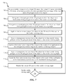
- FIG. 7 is a flow diagram illustrating one embodiment of a method 700 to render a virtual 3-D space.
- the method 700 may be implemented by the rendering module 104 illustrated in FIG. 1, 2 , or 4 .
- the method 700 may be implemented by the application 202 illustrated in FIG. 2 .
- a render viewpoint of a virtual 3-D space may be selected.
- the virtual 3-D space may include a 3-D model of at least a portion of a user generated from an image of the user and a 3-D polygon mesh of an object.
- a first polygon of the 3-D polygon mesh of the object may be designated as a backwards-facing polygon in relation to the render viewing angle.
- a second polygon of the 3-D polygon mesh of the object may be designated as a front-facing polygon in relation to the render viewing angle.
- a shadow texture map of the object may be applied to the 3-D model of the user at the render viewing angle.
- a transparency texture map of the object may be applied to the backwards-facing polygon of the 3-D polygon mesh of the object at the render viewing angle.
- a first color texture map of the object may be applied to the result of the application of the transparency texture map to the backwards-facing polygon.
- a transparency texture map of the object may be applied to the backwards-facing polygon of the 3-D polygon mesh of the object at the render viewing angle.
- the first color texture map of the object may be applied to the result of the application of the transparency texture map to the backwards-facing polygon.
- the virtual 3-D space may be rendered at the render viewing angle.
- a determination may be made whether there is another viewing angle to render. If it is determined that there is another viewing angle to render, then the method 700 returns to block 702 .
- FIG. 8 is a flow diagram illustrating one embodiment of a method 800 to create a shadow texture map.
- the method 800 may be implemented by the rendering module 104 illustrated in FIG. 1, 2 , or 4 .
- the method 800 may be implemented by the application 202 illustrated in FIG. 2 .
- a shadow value of an object may be detected from a scan of the object.
- a shadow texture map may be created from the detected shadow value.
- a 2-D coordinate of the shadow texture map may be mapped to a point on the 3-D model of the user.
- a value of the point on the 3-D model of the user may be multiplied by the shadow value.
- FIG. 9 is a flow diagram illustrating one embodiment of a method 900 to create a transparency texture map.
- the method 900 may be implemented by the rendering module 104 illustrated in FIG. 1, 2 , or 4 .
- the method 900 may be implemented by the application 202 illustrated in FIG. 2 .
- a transparency value of an object may be detected from a scan of the object.
- a transparency texture map may be created from the detected transparency value.
- a 2-D coordinate of the transparency texture map may be mapped to a point on the 3-D model of the user.
- a value of the point on the 3-D model of the user may be multiplied by the transparency value.
- FIG. 10 is a flow diagram illustrating one embodiment of a method 1000 to create a color texture map.
- the method 1000 may be implemented by the rendering module 104 illustrated in FIG. 1, 2 , or 4 .
- the method 1000 may be implemented by the application 202 illustrated in FIG. 2 .
- a scanning angle of a scan of an object may be selected.
- the scanning angle may correspond to a render viewing angle of a 3-D polygon mesh of the object.
- a color value of an object may be detected from a scan of the object.
- a color texture map may be created from the detected color value.
- a 2-D coordinate of the color texture map may be mapped to a point on the 3-D model of the user.
- a value of the point on the 3-D model of the user may be multiplied by the color value.
- a determination may be made whether there is another scanning angle to process. If it is determined that there is another scanning angle to process, then the method 1000 returns to block 1002 .
- FIG. 11 is a flow diagram illustrating another embodiment of a method 1100 to render the virtual 3-D space.
- the method 1100 may be implemented by the rendering module 104 illustrated in FIG. 1, 2 , or 4 .
- the method 1100 may be implemented by the application 202 illustrated in FIG. 2 .
- the 3-D polygon mesh of the object may be divided into multiple parts.
- an order may be determined to the multiple parts of the divided 3-D polygon mesh of the object from furthest part to closest part relative to the determined render viewing angle of the virtual 3-D space.
- the 3-D polygon mesh of the object is rendered from the furthest part to the closest part based on the determined visible portions of the 3-D polygon mesh of the object.
- FIG. 12 is a flow diagram illustrating one embodiment of a method 1200 to apply a blurring effect to a rendered depiction of the object.
- the method 1200 may be implemented by the rendering module 104 illustrated in FIG. 1, 2 , or 4 .
- the method 1200 may be implemented by the application 202 illustrated in FIG. 2 .
- a first level and a second level of blur accuracy may be determined.
- a first level and a second level of blur intensity may be determined.
- the first level of blur accuracy may be applied at the first level of blur intensity to the rendered depiction of the object.
- an edge of the rendered depiction of the object may be detected.
- the first level of blur accuracy may be applied at the second level of blur intensity to the detected edges of the rendered depiction of the object.
- the second level of blur accuracy is applied to the rendered depiction of the object.
- FIG. 13 depicts a block diagram of a computer system 1300 suitable for implementing the present systems and methods.
- Computer system 1310 includes a bus 1312 which interconnects major subsystems of computer system 1310 , such as a central processor 1314 , a system memory 1316 (typically RAM, but which may also include ROM, flash RAM, or the like), an input/output controller 1318 , an external audio device, such as a speaker system 1320 via an audio output interface 1322 , an external device, such as a display screen 1324 via display adapter 1326 , an keyboard 1332 (interfaced with a keyboard controller 1333 ) (or other input device), multiple USB devices 1392 (interfaced with a USB controller 1391 ), and a storage interface 1334 . Also included are a mouse 1346 (or other point-and-click device) and a network interface 1348 (coupled directly to bus 1312 ).
- a mouse 1346 or other point-and-click device
- network interface 1348 coupled directly to bus 1312
- Bus 1312 allows data communication between central processor 1314 and system memory 1316 , which may include read-only memory (ROM) or flash memory (neither shown), and random access memory (RAM) (not shown), as previously noted.
- the RAM is generally the main memory into which the operating system and application programs are loaded.
- the ROM or flash memory can contain, among other code, the Basic Input-Output system (BIOS) which controls basic hardware operation such as the interaction with peripheral components or devices.
- BIOS Basic Input-Output system
- the rendering module 104 - c to implement the present systems and methods may be stored within the system memory 1316 .
- Applications e.g., application 202 resident with computer system 1310 are generally stored on and accessed via a non-transitory computer readable medium, such as a hard disk drive (e.g., fixed disk 1344 ) or other storage medium. Additionally, applications can be in the form of electronic signals modulated in accordance with the application and data communication technology when accessed via interface 1348 .
- a non-transitory computer readable medium such as a hard disk drive (e.g., fixed disk 1344 ) or other storage medium.
- applications can be in the form of electronic signals modulated in accordance with the application and data communication technology when accessed via interface 1348 .
- Storage interface 1334 can connect to a standard computer readable medium for storage and/or retrieval of information, such as a fixed disk drive 1344 .
- Fixed disk drive 1344 may be a part of computer system 1310 or may be separate and accessed through other interface systems.
- Network interface 1348 may provide a direct connection to a remote server via a direct network link to the Internet via a POP (point of presence).
- Network interface 1348 may provide such connection using wireless techniques, including digital cellular telephone connection, Cellular Digital Packet Data (CDPD) connection, digital satellite data connection, or the like.
- CDPD Cellular Digital Packet Data
- FIG. 13 Many other devices or subsystems (not shown) may be connected in a similar manner (e.g., document scanners, digital cameras, and so on). Conversely, all of the devices shown in FIG. 13 need not be present to practice the present systems and methods.
- the devices and subsystems can be interconnected in different ways from that shown in FIG. 13 .
- the operation of a computer system such as that shown in FIG. 13 is readily known in the art and is not discussed in detail in this application.
- Code to implement the present disclosure can be stored in a non-transitory computer-readable medium such as one or more of system memory 1316 or fixed disk 1344 .
- the operating system provided on computer system 1310 may be iOS®, MS-DOS®, MS-WINDOWS®, OS/2®, UNIX®, Linux®, or another known operating system.
- a signal can be directly transmitted from a first block to a second block, or a signal can be modified (e.g., amplified, attenuated, delayed, latched, buffered, inverted, filtered, or otherwise modified) between the blocks.
- a signal can be directly transmitted from a first block to a second block, or a signal can be modified (e.g., amplified, attenuated, delayed, latched, buffered, inverted, filtered, or otherwise modified) between the blocks.
- a signal input at a second block can be conceptualized as a second signal derived from a first signal output from a first block due to physical limitations of the circuitry involved (e.g., there will inevitably be some attenuation and delay). Therefore, as used herein, a second signal derived from a first signal includes the first signal or any modifications to the first signal, whether due to circuit limitations or due to passage through other circuit elements which do not change the informational and/or final functional aspect of the first signal.
- the terms “a” or “an,” as used in the specification and claims, are to be construed as meaning “at least one of.”
- the words “including” and “having,” as used in the specification and claims are interchangeable with and have the same meaning as the word “comprising.”
- the term “based on” as used in the specification and the claims is to be construed as meaning “based at least upon.”
Abstract
Description
Claims (40)
Priority Applications (5)
| Application Number | Priority Date | Filing Date | Title |
|---|---|---|---|
| US13/774,958 US9378584B2 (en) | 2012-05-23 | 2013-02-22 | Systems and methods for rendering virtual try-on products |
| AU2013266187A AU2013266187B2 (en) | 2012-05-23 | 2013-05-23 | Systems and methods for rendering virtual try-on products |
| PCT/US2013/042517 WO2013177459A1 (en) | 2012-05-23 | 2013-05-23 | Systems and methods for rendering virtual try-on products |
| EP13793686.0A EP2852934B1 (en) | 2012-05-23 | 2013-05-23 | Systems and methods for rendering virtual try-on products |
| CA2874531A CA2874531C (en) | 2012-05-23 | 2013-05-23 | Systems and methods for rendering virtual try-on products |
Applications Claiming Priority (3)
| Application Number | Priority Date | Filing Date | Title |
|---|---|---|---|
| US201261650983P | 2012-05-23 | 2012-05-23 | |
| US201261735951P | 2012-12-11 | 2012-12-11 | |
| US13/774,958 US9378584B2 (en) | 2012-05-23 | 2013-02-22 | Systems and methods for rendering virtual try-on products |
Publications (2)
| Publication Number | Publication Date |
|---|---|
| US20130314410A1 US20130314410A1 (en) | 2013-11-28 |
| US9378584B2 true US9378584B2 (en) | 2016-06-28 |
Family
ID=49621242
Family Applications (6)
| Application Number | Title | Priority Date | Filing Date |
|---|---|---|---|
| US13/774,978 Active 2033-08-27 US9235929B2 (en) | 2012-05-23 | 2013-02-22 | Systems and methods for efficiently processing virtual 3-D data |
| US13/774,958 Active 2034-01-19 US9378584B2 (en) | 2012-05-23 | 2013-02-22 | Systems and methods for rendering virtual try-on products |
| US13/774,983 Abandoned US20130314401A1 (en) | 2012-05-23 | 2013-02-22 | Systems and methods for generating a 3-d model of a user for a virtual try-on product |
| US13/774,985 Active 2033-05-23 US9311746B2 (en) | 2012-05-23 | 2013-02-22 | Systems and methods for generating a 3-D model of a virtual try-on product |
| US13/775,764 Active 2033-06-13 US9208608B2 (en) | 2012-05-23 | 2013-02-25 | Systems and methods for feature tracking |
| US14/698,655 Active US10147233B2 (en) | 2012-05-23 | 2015-04-28 | Systems and methods for generating a 3-D model of a user for a virtual try-on product |
Family Applications Before (1)
| Application Number | Title | Priority Date | Filing Date |
|---|---|---|---|
| US13/774,978 Active 2033-08-27 US9235929B2 (en) | 2012-05-23 | 2013-02-22 | Systems and methods for efficiently processing virtual 3-D data |
Family Applications After (4)
| Application Number | Title | Priority Date | Filing Date |
|---|---|---|---|
| US13/774,983 Abandoned US20130314401A1 (en) | 2012-05-23 | 2013-02-22 | Systems and methods for generating a 3-d model of a user for a virtual try-on product |
| US13/774,985 Active 2033-05-23 US9311746B2 (en) | 2012-05-23 | 2013-02-22 | Systems and methods for generating a 3-D model of a virtual try-on product |
| US13/775,764 Active 2033-06-13 US9208608B2 (en) | 2012-05-23 | 2013-02-25 | Systems and methods for feature tracking |
| US14/698,655 Active US10147233B2 (en) | 2012-05-23 | 2015-04-28 | Systems and methods for generating a 3-D model of a user for a virtual try-on product |
Country Status (5)
| Country | Link |
|---|---|
| US (6) | US9235929B2 (en) |
| EP (2) | EP2852935B1 (en) |
| AU (1) | AU2013266187B2 (en) |
| CA (1) | CA2874531C (en) |
| WO (5) | WO2013177448A1 (en) |
Cited By (2)
| Publication number | Priority date | Publication date | Assignee | Title |
|---|---|---|---|---|
| US20180095295A1 (en) * | 2016-10-04 | 2018-04-05 | Essilor International (Compagnie Generale D'optique) | Method for determining a geometrical parameter of an eye of a subject |
| US10997794B2 (en) * | 2016-06-01 | 2021-05-04 | Vidi Pty Ltd | Optical measuring and scanning system and methods of use |
Families Citing this family (72)
| Publication number | Priority date | Publication date | Assignee | Title |
|---|---|---|---|---|
| US20140240354A1 (en) * | 2013-02-28 | 2014-08-28 | Samsung Electronics Co., Ltd. | Augmented reality apparatus and method |
| CN104021590A (en) * | 2013-02-28 | 2014-09-03 | 北京三星通信技术研究有限公司 | Virtual try-on system and virtual try-on method |
| US9965887B2 (en) | 2013-03-05 | 2018-05-08 | Autodesk, Inc. | Technique for mapping a texture onto a three-dimensional model |
| US9338440B2 (en) * | 2013-06-17 | 2016-05-10 | Microsoft Technology Licensing, Llc | User interface for three-dimensional modeling |
| KR101821284B1 (en) | 2013-08-22 | 2018-01-23 | 비스포크, 인코포레이티드 | Method and system to create custom products |
| EP2919450B1 (en) * | 2014-03-11 | 2020-09-09 | Wipro Limited | A method and a guided imaging unit for guiding a user to capture an image |
| WO2015137788A1 (en) * | 2014-03-14 | 2015-09-17 | Samsung Electronics Co., Ltd. | Electronic apparatus for providing health status information, method of controlling the same, and computer-readable storage medium |
| TWI576232B (en) * | 2014-03-25 | 2017-04-01 | Dws有限責任公司 | Improved computer-implemented method for defining the points of development of supporting elements of an object made by means of a stereolithography process |
| KR102225620B1 (en) * | 2014-04-03 | 2021-03-12 | 한화테크윈 주식회사 | Camera modeling system |
| US9996899B2 (en) * | 2014-05-08 | 2018-06-12 | Glasses.Com Inc. | Systems and methods for scaling an object |
| CN104217350B (en) * | 2014-06-17 | 2017-03-22 | 北京京东尚科信息技术有限公司 | Virtual try-on realization method and device |
| US9665984B2 (en) * | 2014-07-31 | 2017-05-30 | Ulsee Inc. | 2D image-based 3D glasses virtual try-on system |
| US10176625B2 (en) | 2014-09-25 | 2019-01-08 | Faro Technologies, Inc. | Augmented reality camera for use with 3D metrology equipment in forming 3D images from 2D camera images |
| KR20160046399A (en) * | 2014-10-20 | 2016-04-29 | 삼성에스디에스 주식회사 | Method and Apparatus for Generation Texture Map, and Database Generation Method |
| FR3027505B1 (en) * | 2014-10-27 | 2022-05-06 | H 43 | METHOD FOR CONTROLLING THE POSITIONING OF TEETH |
| KR102272310B1 (en) * | 2014-11-18 | 2021-07-02 | 삼성전자주식회사 | Method of processing images, Computer readable storage medium of recording the method and an electronic apparatus |
| US9506744B2 (en) | 2014-12-16 | 2016-11-29 | Faro Technologies, Inc. | Triangulation scanner and camera for augmented reality |
| KR102296820B1 (en) * | 2015-01-27 | 2021-09-02 | 삼성전자주식회사 | Method and apparatus for forming 2d texture map of facial image |
| EP3265999A4 (en) | 2015-03-01 | 2018-08-22 | NEXTVR Inc. | Methods and apparatus for 3d image rendering |
| US10373343B1 (en) * | 2015-05-28 | 2019-08-06 | Certainteed Corporation | System for visualization of a building material |
| WO2017129842A1 (en) * | 2016-01-25 | 2017-08-03 | Ópticas Claravisión, S.L. | Method for producing lenses and frames with personalised design and remote bevelling of corrective lenses, and optical device for morphological measurement for performing said method |
| CN105913496B (en) * | 2016-04-06 | 2018-09-28 | 成都景和千城科技有限公司 | It is a kind of by true dress ornament rapid translating be three-dimensional dress ornament method and system |
| US10672180B2 (en) | 2016-05-02 | 2020-06-02 | Samsung Electronics Co., Ltd. | Method, apparatus, and recording medium for processing image |
| US10008024B2 (en) | 2016-06-08 | 2018-06-26 | Qualcomm Incorporated | Material-aware three-dimensional scanning |
| FR3053509B1 (en) * | 2016-06-30 | 2019-08-16 | Fittingbox | METHOD FOR OCCULATING AN OBJECT IN AN IMAGE OR A VIDEO AND ASSOCIATED AUGMENTED REALITY METHOD |
| US10217265B2 (en) | 2016-07-07 | 2019-02-26 | Disney Enterprises, Inc. | Methods and systems of generating a parametric eye model |
| US10217275B2 (en) * | 2016-07-07 | 2019-02-26 | Disney Enterprises, Inc. | Methods and systems of performing eye reconstruction using a parametric model |
| US10762717B2 (en) * | 2016-09-29 | 2020-09-01 | Sony Interactive Entertainment America, LLC | Blend shape system with dynamic partitioning |
| US10275925B2 (en) | 2016-09-29 | 2019-04-30 | Sony Interactive Entertainment America, LLC | Blend shape system with texture coordinate blending |
| IL294635B2 (en) * | 2016-10-05 | 2024-02-01 | Magic Leap Inc | Surface modeling systems and methods |
| US10043317B2 (en) | 2016-11-18 | 2018-08-07 | International Business Machines Corporation | Virtual trial of products and appearance guidance in display device |
| US10943100B2 (en) | 2017-01-19 | 2021-03-09 | Mindmaze Holding Sa | Systems, methods, devices and apparatuses for detecting facial expression |
| US10679408B2 (en) * | 2017-02-02 | 2020-06-09 | Adobe Inc. | Generating a three-dimensional model from a scanned object |
| US11367198B2 (en) * | 2017-02-07 | 2022-06-21 | Mindmaze Holding Sa | Systems, methods, and apparatuses for tracking a body or portions thereof |
| CN109035381B (en) * | 2017-06-08 | 2021-11-09 | 福建天晴数码有限公司 | Cartoon picture hair rendering method and storage medium based on UE4 platform |
| CN107481082A (en) * | 2017-06-26 | 2017-12-15 | 珠海格力电器股份有限公司 | A kind of virtual fit method and its device, electronic equipment and virtual fitting system |
| CN107610239B (en) * | 2017-09-14 | 2020-11-03 | 广州帕克西软件开发有限公司 | Virtual try-on method and device for facial makeup |
| JP2019070872A (en) * | 2017-10-05 | 2019-05-09 | カシオ計算機株式会社 | Image processing device, image processing method, and program |
| US10613710B2 (en) * | 2017-10-22 | 2020-04-07 | SWATCHBOOK, Inc. | Product simulation and control system for user navigation and interaction |
| GB2569546B (en) * | 2017-12-19 | 2020-10-14 | Sony Interactive Entertainment Inc | Determining pixel values using reference images |
| CN109979013B (en) * | 2017-12-27 | 2021-03-02 | Tcl科技集团股份有限公司 | Three-dimensional face mapping method and terminal equipment |
| CN108629837A (en) * | 2018-01-09 | 2018-10-09 | 南京大学 | A kind of cloth real-time emulation method for virtual fitting |
| US11328533B1 (en) | 2018-01-09 | 2022-05-10 | Mindmaze Holding Sa | System, method and apparatus for detecting facial expression for motion capture |
| US20190228580A1 (en) * | 2018-01-24 | 2019-07-25 | Facebook, Inc. | Dynamic Creation of Augmented Reality Effects |
| US10839578B2 (en) * | 2018-02-14 | 2020-11-17 | Smarter Reality, LLC | Artificial-intelligence enhanced visualization of non-invasive, minimally-invasive and surgical aesthetic medical procedures |
| US10769851B1 (en) * | 2018-04-29 | 2020-09-08 | Dustin Kyle Nolen | Method for producing a scaled-up solid model of microscopic features of a surface |
| US11126160B1 (en) * | 2018-04-29 | 2021-09-21 | Dustin Kyle Nolen | Method for producing a scaled-up solid model of microscopic features of a surface |
| US10789696B2 (en) * | 2018-05-24 | 2020-09-29 | Tfi Digital Media Limited | Patch selection for neural network based no-reference image quality assessment |
| US11195324B1 (en) | 2018-08-14 | 2021-12-07 | Certainteed Llc | Systems and methods for visualization of building structures |
| US10997396B2 (en) * | 2019-04-05 | 2021-05-04 | Realnetworks, Inc. | Face liveness detection systems and methods |
| CN110175897A (en) * | 2019-06-03 | 2019-08-27 | 广东元一科技实业有限公司 | A kind of 3D synthesis fitting method and system |
| WO2021117481A1 (en) * | 2019-12-09 | 2021-06-17 | ソニーグループ株式会社 | Data processing device, data processing method, and program |
| US11430142B2 (en) | 2020-04-28 | 2022-08-30 | Snap Inc. | Photometric-based 3D object modeling |
| CN111743273B (en) * | 2020-05-21 | 2022-09-30 | 中国地质大学(北京) | Polarizing jewelry and identity recognition method using same |
| CN111773707A (en) * | 2020-08-11 | 2020-10-16 | 网易(杭州)网络有限公司 | Rendering processing method and device, electronic equipment and storage medium |
| US11551421B1 (en) | 2020-10-16 | 2023-01-10 | Splunk Inc. | Mesh updates via mesh frustum cutting |
| US11127223B1 (en) | 2020-10-16 | 2021-09-21 | Splunkinc. | Mesh updates via mesh splitting |
| US11798235B1 (en) | 2020-10-16 | 2023-10-24 | Splunk Inc. | Interactions in networked remote collaboration environments |
| US11544904B1 (en) * | 2020-10-16 | 2023-01-03 | Splunk Inc. | Mesh updates in an extended reality environment |
| US11546437B1 (en) | 2020-10-16 | 2023-01-03 | Splunk Inc. | Playback of a stored networked remote collaboration session |
| US11727643B1 (en) | 2020-10-16 | 2023-08-15 | Splunk Inc. | Multi-environment networked remote collaboration system |
| US11776218B1 (en) | 2020-10-16 | 2023-10-03 | Splunk Inc. | Networked remote collaboration system |
| US11563813B1 (en) | 2020-10-16 | 2023-01-24 | Splunk Inc. | Presentation of collaboration environments for a networked remote collaboration session |
| US11494732B2 (en) | 2020-10-30 | 2022-11-08 | International Business Machines Corporation | Need-based inventory |
| US11663764B2 (en) | 2021-01-27 | 2023-05-30 | Spree3D Corporation | Automatic creation of a photorealistic customized animated garmented avatar |
| US20220207828A1 (en) * | 2020-12-30 | 2022-06-30 | Spree3D Corporation | Systems and methods of three-dimensional modeling for use in generating a realistic computer avatar and garments |
| US20220343601A1 (en) * | 2021-04-21 | 2022-10-27 | Fyusion, Inc. | Weak multi-view supervision for surface mapping estimation |
| US11836905B2 (en) | 2021-06-03 | 2023-12-05 | Spree3D Corporation | Image reenactment with illumination disentanglement |
| US11769346B2 (en) | 2021-06-03 | 2023-09-26 | Spree3D Corporation | Video reenactment with hair shape and motion transfer |
| US11854579B2 (en) | 2021-06-03 | 2023-12-26 | Spree3D Corporation | Video reenactment taking into account temporal information |
| WO2023278488A1 (en) * | 2021-06-29 | 2023-01-05 | Variable Technologies Corporation | Systems and methods for volumizing and encoding two-dimensional images |
| US20230027519A1 (en) * | 2021-07-13 | 2023-01-26 | Tencent America LLC | Image based sampling metric for quality assessment |
Citations (471)
| Publication number | Priority date | Publication date | Assignee | Title |
|---|---|---|---|---|
| US3927933A (en) | 1973-08-06 | 1975-12-23 | Humphrey Instruments Inc | Apparatus for opthalmological prescription readout |
| US4370058A (en) | 1979-08-24 | 1983-01-25 | Carl Zeiss-Stiftung | Digital focimeter and method |
| EP0092364A1 (en) | 1982-04-14 | 1983-10-26 | The Hanwell Optical Co. Limited | A method of and apparatus for dimensioning a lens to fit a spectacle frame |
| US4467349A (en) | 1982-04-07 | 1984-08-21 | Maloomian Laurence G | System and method for composite display |
| US4522474A (en) | 1980-05-20 | 1985-06-11 | Slavin Sidney H | Spinning optics device |
| US4534650A (en) | 1981-04-27 | 1985-08-13 | Inria Institut National De Recherche En Informatique Et En Automatique | Device for the determination of the position of points on the surface of a body |
| US4539585A (en) | 1981-07-10 | 1985-09-03 | Spackova Daniela S | Previewer |
| US4573121A (en) | 1982-09-24 | 1986-02-25 | Hoya Lens Corporation | Method for determining optimum thickness of ophthalmic lens |
| US4613219A (en) | 1984-03-05 | 1986-09-23 | Burke Marketing Services, Inc. | Eye movement recording apparatus |
| US4698564A (en) | 1980-05-20 | 1987-10-06 | Slavin Sidney H | Spinning optics device |
| US4724617A (en) | 1986-08-14 | 1988-02-16 | Gerber Scientific Products, Inc. | Apparatus for tracing the lens opening in an eyeglass frame |
| US4730260A (en) | 1984-09-28 | 1988-03-08 | Asahi Glass Company Ltd. | Method for eyewear simulation and a device for its practice |
| US4781452A (en) | 1984-11-07 | 1988-11-01 | Ace Ronald S | Modular optical manufacturing system |
| US4786160A (en) | 1985-05-14 | 1988-11-22 | Carl-Zeiss-Stiftung | Multi-focal spectacle lens having at least one progressive surface |
| US4845641A (en) | 1986-09-19 | 1989-07-04 | Hoya Corporation | Method of forming a synthetic image in simulation system for attachment of spectacles |
| US4852184A (en) | 1986-10-30 | 1989-07-25 | Kabushiki Kaisha Toshiba | Method and system for spectacles frame image processing and recording |
| EP0359596A1 (en) | 1988-09-08 | 1990-03-21 | Briot International | Data transmission installation to facilitate and accelerate the manufacture of spectacle glasses |
| US4957369A (en) | 1989-01-23 | 1990-09-18 | California Institute Of Technology | Apparatus for measuring three-dimensional surface geometries |
| US5139373A (en) | 1986-08-14 | 1992-08-18 | Gerber Optical, Inc. | Optical lens pattern making system and method |
| WO1993000641A1 (en) | 1991-06-25 | 1993-01-07 | Patrice Chainet | Cash desk management aid system for a retail outlet, and method of implementation |
| US5255352A (en) | 1989-08-03 | 1993-10-19 | Computer Design, Inc. | Mapping of two-dimensional surface detail on three-dimensional surfaces |
| US5257198A (en) | 1991-12-18 | 1993-10-26 | Schoyck Carol G Van | Method of transmitting edger information to a remote numerically controlled edger |
| US5280570A (en) | 1992-09-11 | 1994-01-18 | Jordan Arthur J | Spectacle imaging and lens simulating system and method |
| US5281957A (en) | 1984-11-14 | 1994-01-25 | Schoolman Scientific Corp. | Portable computer and head mounted display |
| US5428448A (en) | 1993-10-20 | 1995-06-27 | Augen Wecken Plasticos S.R.L. De C.V. | Method and apparatus for non-contact digitazation of frames and lenses |
| US5485399A (en) | 1992-06-24 | 1996-01-16 | Hoya Corporation | Spectacle lens supply method |
| WO1996004596A1 (en) | 1994-08-01 | 1996-02-15 | Wernicke & Co. Gmbh | Method of determining spectacle lens edge data |
| US5550602A (en) | 1994-11-09 | 1996-08-27 | Johannes Braeuning | Apparatus and method for examining visual functions |
| US5592248A (en) | 1995-11-16 | 1997-01-07 | Norton; Ross A. | Computerized method for fitting eyeglasses |
| US5631718A (en) | 1995-02-01 | 1997-05-20 | Bausch & Lomb Incorporated | Temple for eyewear |
| US5666957A (en) | 1992-08-12 | 1997-09-16 | Juto; Jan-Erik | Method and device for rhinostereometric measurement |
| US5682210A (en) | 1995-12-08 | 1997-10-28 | Weirich; John | Eye contact lens video display system |
| WO1997040342A2 (en) | 1996-04-24 | 1997-10-30 | Cyra Technologies, Inc. | Integrated system for imaging and modeling three-dimensional objects |
| WO1997040960A1 (en) | 1996-04-25 | 1997-11-06 | Rainer Jung | Machine for stock-removing machining of optical materials for the manufacture of optical components |
| US5720649A (en) | 1995-12-22 | 1998-02-24 | Gerber Optical, Inc. | Optical lens or lap blank surfacing machine, related method and cutting tool for use therewith |
| US5724522A (en) | 1994-11-17 | 1998-03-03 | Hitachi, Ltd. | Method for trying-on apparel electronically while protecting private data |
| WO1998013721A1 (en) | 1996-09-26 | 1998-04-02 | Mcdonnell Douglas Corporation | Head mounted display with fibre optic image transfer from flat panel |
| US5774129A (en) | 1995-06-07 | 1998-06-30 | Massachusetts Institute Of Technology | Image analysis and synthesis networks using shape and texture information |
| WO1998027902A2 (en) | 1996-12-20 | 1998-07-02 | Bausch & Lomb Incorporated | Multi-sport goggle with interchangeable straps and tear-away lens system |
| WO1998035263A1 (en) | 1997-02-06 | 1998-08-13 | Bausch & Lomb Incorporated | Electric connection configuration for electro-optical device |
| WO1998052189A2 (en) | 1997-05-15 | 1998-11-19 | Palantir Software, Inc. | Multimedia interface with user interaction tracking |
| US5844573A (en) | 1995-06-07 | 1998-12-01 | Massachusetts Institute Of Technology | Image compression by pointwise prototype correspondence using shape and texture information |
| WO1998057270A1 (en) | 1997-06-13 | 1998-12-17 | Fay Pierre N | A system and method enabling shopping from home for fitted eyeglass frames |
| US5880806A (en) | 1997-10-16 | 1999-03-09 | Bausch & Lomb Incorporated | Eyewear frame construction |
| US5908348A (en) | 1997-01-23 | 1999-06-01 | Wernicke & Co. Gmbh | Method for CNC-controlled shape grinding of spectacle lenses |
| WO1999056942A1 (en) | 1998-05-07 | 1999-11-11 | Luxottica Leasing S.P.A. | Eyewear frame construction |
| US5987702A (en) | 1997-05-29 | 1999-11-23 | Luxottica Leasing S.P.A. | Connecting device, particularly for eyeglasses |
| WO1999064918A1 (en) | 1998-06-12 | 1999-12-16 | Luxottica Leasing S.P.A. | Eyewear with replaceable lens system |
| USD417883S (en) | 1999-03-03 | 1999-12-21 | Luxottica Leasing S.P.A. | Eyewear temple |
| WO2000000863A1 (en) | 1998-06-26 | 2000-01-06 | Luxottica Leasing S.P.A. | Sunglass lens laminate |
| US6016150A (en) * | 1995-08-04 | 2000-01-18 | Microsoft Corporation | Sprite compositor and method for performing lighting and shading operations using a compositor to combine factored image layers |
| US6018339A (en) | 1997-08-15 | 2000-01-25 | Stevens; Susan | Automatic visual correction for computer screen |
| USD420037S (en) | 1998-11-19 | 2000-02-01 | Luxottica Leasing S.P.A. | Eyewear |
| USD420380S (en) | 1998-07-31 | 2000-02-08 | Luxottica Leasing S.P.A. | Eyewear temple |
| USD420379S (en) | 1999-03-01 | 2000-02-08 | Luxottica Leasing S.P.A. | Eyewear front |
| US6024444A (en) | 1998-12-18 | 2000-02-15 | Luxottica Leasing S.P.A. | Eyewear lens retention apparatus and method |
| USD421764S (en) | 1999-04-05 | 2000-03-21 | Luxottica Leasing S.P.A. | Eyewear front |
| USD422011S (en) | 1999-04-29 | 2000-03-28 | Luxottica Leasing S.P.A. | Eyewear front |
| WO2000016683A1 (en) | 1998-09-22 | 2000-03-30 | Virtual Visual Devices, Llc. | Interactive eyewear selection system |
| USD423034S (en) | 1999-02-19 | 2000-04-18 | Luxottica Leasing S.P.A. | Eyewear |
| EP0994336A2 (en) | 1998-10-12 | 2000-04-19 | Hoya Corporation | Spectacle lens evaluation method and evaluation device |
| USD423553S (en) | 1999-06-24 | 2000-04-25 | Luxottica Leasing S.P.A. | Eyewear |
| USD423556S (en) | 1999-04-30 | 2000-04-25 | Luxottica Leasing S.P.A. | Eyewear |
| USD423557S (en) | 1999-09-01 | 2000-04-25 | Luxottica Leasing S.P.A. | Eyewear temple |
| USD423554S (en) | 1999-06-24 | 2000-04-25 | Luxottica Leasing S.P.A. | Eyewear front |
| USD423552S (en) | 1999-04-30 | 2000-04-25 | Luxottica Leasing S.P.A. | Eyewear |
| USD424095S (en) | 1999-02-03 | 2000-05-02 | Luxottica Leasing S.P.A. | Eyewear front |
| USD424096S (en) | 1999-05-12 | 2000-05-02 | Luxottica Leasing S.P.A. | Eyewear front |
| USD424094S (en) | 1999-04-30 | 2000-05-02 | Luxottica Leasing S.P.A. | Eyewear |
| USD424598S (en) | 1997-09-30 | 2000-05-09 | Luxottica Leasing S.P.A. | Eyewear |
| USD424589S (en) | 1999-06-02 | 2000-05-09 | Luxottica Leasing S.P.A | Eyewear lens |
| USD425542S (en) | 1999-05-27 | 2000-05-23 | Luxottica Leasing S.P.A. | Eyewear |
| USD425543S (en) | 1998-08-21 | 2000-05-23 | Luxottica Leasing S.P.A. | Eyewear |
| KR20000028583A (en) | 1998-10-02 | 2000-05-25 | 윤종용 | 3-D mesh coding/decoding method and apparatus for error resilience and incremental rendering |
| US6072496A (en) | 1998-06-08 | 2000-06-06 | Microsoft Corporation | Method and system for capturing and representing 3D geometry, color and shading of facial expressions and other animated objects |
| USD426568S (en) | 1999-03-01 | 2000-06-13 | Luxottica Leasing S.P.A. | Eyewear |
| EP1011006A1 (en) | 1997-05-16 | 2000-06-21 | Hoya Corporation | System for making spectacles to order |
| USD427225S (en) | 1999-04-08 | 2000-06-27 | Luxottica Leasing S.P.A. | Goggle |
| USD427227S (en) | 1999-02-09 | 2000-06-27 | Luxottica Leasing S.P.A. | Eyewear |
| WO2000045348A1 (en) | 1999-01-28 | 2000-08-03 | Jang Doo Soon | Ticket selling method and apparatus |
| WO2000049919A1 (en) | 1999-02-26 | 2000-08-31 | Dash-It Usa Inc. | Magnetic coupler and various embodiments thereof |
| USD430591S (en) | 1999-11-01 | 2000-09-05 | Luxottica Leasing S.P.A. | Eyewear temple |
| USD432156S (en) | 1998-11-19 | 2000-10-17 | Luxottica Leasing S.P.A. | Eyewear |
| US6132044A (en) | 1998-11-20 | 2000-10-17 | Luxottica Leasing S.P.A | Filter for a special purpose lens and method of making filter |
| WO2000062148A1 (en) | 1999-04-09 | 2000-10-19 | Francesco Lauricella | Optical keyboard for a personal computer activated by a light emitting device worn on a handicapped user's head |
| WO2000064168A1 (en) | 1999-04-19 | 2000-10-26 | I Pyxidis Llc | Methods and apparatus for delivering and viewing distributed entertainment broadcast objects as a personalized interactive telecast |
| US6139143A (en) | 1997-12-11 | 2000-10-31 | Bausch & Lomb Incorporated | Temple for eyewear having an integrally formed serpentine hinge |
| US6139141A (en) | 1998-05-20 | 2000-10-31 | Altair Holding Company | Auxiliary eyeglasses with magnetic clips |
| USD433052S (en) | 1998-05-06 | 2000-10-31 | Luxottica Leasing S.P.A. | Eyewear |
| US6144388A (en) | 1998-03-06 | 2000-11-07 | Bornstein; Raanan | Process for displaying articles of clothing on an image of a person |
| US6142628A (en) | 1998-02-03 | 2000-11-07 | Saigo; Tsuyoshi | Eyeglasses try-on simulation system |
| USD434788S (en) | 1999-12-15 | 2000-12-05 | Luxottica Leasing S.P.A. | Eyewear |
| US6208347B1 (en) | 1997-06-23 | 2001-03-27 | Real-Time Geometry Corporation | System and method for computer modeling of 3D objects and 2D images by mesh constructions that incorporate non-spatial data such as color or texture |
| WO2001023908A1 (en) | 1999-09-24 | 2001-04-05 | Eyeweb Inc. | Automated image scaling |
| US6222621B1 (en) | 1998-10-12 | 2001-04-24 | Hoyo Corporation | Spectacle lens evaluation method and evaluation device |
| WO2001032074A1 (en) | 1999-11-04 | 2001-05-10 | Stefano Soatto | System for selecting and designing eyeglass frames |
| US6233049B1 (en) | 1998-03-25 | 2001-05-15 | Minolta Co., Ltd. | Three-dimensional measurement apparatus |
| WO2001035338A1 (en) | 1999-11-09 | 2001-05-17 | Newag Digital, Llc | System and method for accurately displaying superimposed images |
| US6249600B1 (en) | 1997-11-07 | 2001-06-19 | The Trustees Of Columbia University In The City Of New York | System and method for generation of a three-dimensional solid model |
| WO2001061447A1 (en) | 2000-02-17 | 2001-08-23 | The Jim Henson Company | Live performance control of computer graphic characters |
| US6281903B1 (en) | 1998-12-04 | 2001-08-28 | International Business Machines Corporation | Methods and apparatus for embedding 2D image content into 3D models |
| DE10007705A1 (en) | 2000-02-19 | 2001-09-06 | Keune Thomas | Method for matching spectacles to potential wearer via Internet, in which wearer records images of themselves wearing reference marker, using digital camera connected to computer and these are transmitted to server |
| WO2001067325A1 (en) | 2000-03-08 | 2001-09-13 | Pia Corporation | Electronic ticket transfer system |
| US20010023413A1 (en) | 2000-03-17 | 2001-09-20 | Yasufumi Fukuma | Eyeglass frame synthesizing system and eyeglass frame selling method |
| EP1136869A1 (en) | 2000-03-17 | 2001-09-26 | Kabushiki Kaisha TOPCON | Eyeglass frame selecting system |
| US20010026272A1 (en) | 2000-04-03 | 2001-10-04 | Avihay Feld | System and method for simulation of virtual wear articles on virtual models |
| EP1138253A2 (en) | 2000-03-30 | 2001-10-04 | Kabushiki Kaisha TOPCON | Eye test system |
| WO2001074553A2 (en) | 2000-03-30 | 2001-10-11 | Q2100, Inc. | Software for operating a lens forming apparatus |
| US6307568B1 (en) | 1998-10-28 | 2001-10-23 | Imaginarix Ltd. | Virtual dressing over the internet |
| WO2001078630A1 (en) | 2000-04-14 | 2001-10-25 | Pavel Efimovich Golikov | Method for increasing visual working capacity when one is working with display facilities, light-filter devices for performing said method and method for producing these devices |
| US6310627B1 (en) | 1998-01-20 | 2001-10-30 | Toyo Boseki Kabushiki Kaisha | Method and system for generating a stereoscopic image of a garment |
| WO2001088654A2 (en) | 2000-05-18 | 2001-11-22 | Visionix Ltd. | Spectacles fitting system and fitting methods |
| US20010051517A1 (en) | 2000-06-01 | 2001-12-13 | Jonathan Strietzel | Method and apparatus for telecommunications advertising |
| US20020010655A1 (en) | 2000-05-25 | 2002-01-24 | Realitybuy, Inc. | Real time, three-dimensional, configurable, interactive product display system and method |
| WO2002007845A1 (en) | 2000-07-20 | 2002-01-31 | Juhani Wahlgren | Method and apparatus for displaying of text simultaneously with theatre, opera etc. enactsments or with information of events or expositions |
| US6356271B1 (en) | 1998-02-17 | 2002-03-12 | Silicon Graphics, Inc. | Computer generated paint stamp seaming compensation |
| US6386562B1 (en) | 2000-09-11 | 2002-05-14 | Hui Shan Kuo | Scooter having changeable steering mechanism |
| WO2002041127A2 (en) | 2000-11-16 | 2002-05-23 | Vr Interactive Corporation | Inward-looking imaging system |
| EP0444902B2 (en) | 1990-02-27 | 2002-06-05 | Luxottica Leasing S.p.A. | Lens edging system |
| US6415051B1 (en) | 1999-06-24 | 2002-07-02 | Geometrix, Inc. | Generating 3-D models using a manually operated structured light source |
| US6420698B1 (en) | 1997-04-24 | 2002-07-16 | Cyra Technologies, Inc. | Integrated system for quickly and accurately imaging and modeling three-dimensional objects |
| US6419549B2 (en) | 2000-02-29 | 2002-07-16 | Asahi Kogaku Kogyo Kabushiki Kaisha | Manufacturing method of spectacle lenses and system thereof |
| US20020105530A1 (en) | 2001-02-06 | 2002-08-08 | Roman Waupotitsch | Interactive try-on platform for eyeglasses |
| US6434278B1 (en) | 1997-09-23 | 2002-08-13 | Enroute, Inc. | Generating three-dimensional models of objects defined by two-dimensional image data |
| US6456287B1 (en) | 1999-02-03 | 2002-09-24 | Isurftv | Method and apparatus for 3D model creation based on 2D images |
| US6466205B2 (en) | 1998-11-19 | 2002-10-15 | Push Entertainment, Inc. | System and method for creating 3D models from 2D sequential image data |
| US6492986B1 (en) | 1997-06-02 | 2002-12-10 | The Trustees Of The University Of Pennsylvania | Method for human face shape and motion estimation based on integrating optical flow and deformable models |
| US6493073B2 (en) | 2000-12-11 | 2002-12-10 | Sheldon L. Epstein | System and method for measuring properties of an optical component |
| US6516099B1 (en) | 1997-08-05 | 2003-02-04 | Canon Kabushiki Kaisha | Image processing apparatus |
| US6518963B1 (en) | 1998-07-20 | 2003-02-11 | Geometrix, Inc. | Method and apparatus for generating patches from a 3D mesh model |
| US20030030904A1 (en) | 2001-08-13 | 2003-02-13 | Mei-Ling Huang | Stereoscopic viewing assembly with adjustable fields of vision in two dimensions |
| US6529626B1 (en) | 1998-12-01 | 2003-03-04 | Fujitsu Limited | 3D model conversion apparatus and method |
| US6527731B2 (en) | 2000-12-22 | 2003-03-04 | David Weiss | Control systems for biopsy devices |
| US6535223B1 (en) | 2000-05-31 | 2003-03-18 | Schmidt Laboratories, Inc. | Method and system for determining pupiltary distant and element height |
| US20030071810A1 (en) | 2001-08-31 | 2003-04-17 | Boris Shoov | Simultaneous use of 2D and 3D modeling data |
| US6556196B1 (en) | 1999-03-19 | 2003-04-29 | Max-Planck-Gesellschaft Zur Forderung Der Wissenschaften E.V. | Method and apparatus for the processing of images |
| US20030110099A1 (en) | 2001-12-11 | 2003-06-12 | Philips Electronics North America Corporation | Virtual wearing of clothes |
| US20030112240A1 (en) | 2001-10-10 | 2003-06-19 | Cerny Mark Evan | System and method for point pushing to render polygons in environments with changing levels of detail |
| US6624843B2 (en) | 1999-12-10 | 2003-09-23 | Jerry W. Lennon | Customer image capture and use thereof in a retailing system |
| WO2003079097A1 (en) | 2001-10-25 | 2003-09-25 | Ophthonix, Inc. | Custom eyeglass manufacturing method |
| WO2003084448A1 (en) | 2002-04-11 | 2003-10-16 | Sendo Co., Ltd. | Color-blindness correcting eyeglass and method for manufacturing color-blindness correcting eyeglass |
| US6637880B1 (en) | 1999-02-12 | 2003-10-28 | Hoya Corporation | Spectacle lens and manufacturing method therefor |
| US6647146B1 (en) | 1997-08-05 | 2003-11-11 | Canon Kabushiki Kaisha | Image processing apparatus |
| US6650324B1 (en) | 1999-10-29 | 2003-11-18 | Intel Corporation | Defining surface normals in a 3D surface mesh |
| JP2003345857A (en) | 2000-03-17 | 2003-12-05 | Topcon Corp | Processing simulation apparatus for spectacle lens |
| US6661433B1 (en) | 2000-11-03 | 2003-12-09 | Gateway, Inc. | Portable wardrobe previewing device |
| US6659609B2 (en) | 2000-04-27 | 2003-12-09 | Frank Mothes | Device for determining spectacle lens centering data |
| US6664956B1 (en) | 2000-10-12 | 2003-12-16 | Momentum Bilgisayar, Yazilim, Danismanlik, Ticaret A. S. | Method for generating a personalized 3-D face model |
| US6668082B1 (en) | 1997-08-05 | 2003-12-23 | Canon Kabushiki Kaisha | Image processing apparatus |
| US6671538B1 (en) | 1999-11-26 | 2003-12-30 | Koninklijke Philips Electronics, N.V. | Interface system for use with imaging devices to facilitate visualization of image-guided interventional procedure planning |
| US20040004633A1 (en) | 2002-07-03 | 2004-01-08 | Perry James N. | Web-based system and method for ordering and fitting prescription lens eyewear |
| US6677946B1 (en) | 1999-03-08 | 2004-01-13 | Sony Computer Entertainment Inc. | Method of, an apparatus for, and a recording medium comprising a program for, processing an image |
| US6705718B2 (en) | 2001-04-13 | 2004-03-16 | Luxottica S.R.L. | Spectacle frames with improved stratiform coating |
| US6726463B2 (en) | 2001-02-20 | 2004-04-27 | Q2100, Inc. | Apparatus for preparing an eyeglass lens having a dual computer system controller |
| US20040090438A1 (en) | 2000-06-23 | 2004-05-13 | Pierre Alliez | Refinement of a triangular mesh representing a three- dimensional object |
| US6760488B1 (en) | 1999-07-12 | 2004-07-06 | Carnegie Mellon University | System and method for generating a three-dimensional model from a two-dimensional image sequence |
| US6775128B2 (en) | 2002-10-03 | 2004-08-10 | Julio Leitao | Protective cover sleeve for laptop computer screens |
| EP1450201A1 (en) | 2003-02-22 | 2004-08-25 | Hans-Joachim Ollendorf | Device for determining interpupillery distance |
| US6785585B1 (en) | 1998-02-05 | 2004-08-31 | Wernicke & Co. Gmbh | Method for marking or drilling holes in glass lenses and device for realizing the same |
| US6791584B1 (en) | 2000-09-05 | 2004-09-14 | Yiling Xie | Method of scaling face image with spectacle frame image through computer |
| US6792401B1 (en) | 2000-10-31 | 2004-09-14 | Diamond Visionics Company | Internet-based modeling kiosk and method for fitting and selling prescription eyeglasses |
| JP2004272530A (en) | 2003-03-07 | 2004-09-30 | Digital Fashion Ltd | Virtual fitting display device and method, virtual fitting display program, and computer readable recoding medium with the same program recorded |
| US6807290B2 (en) | 2000-03-09 | 2004-10-19 | Microsoft Corporation | Rapid computer modeling of faces for animation |
| US6808381B2 (en) | 2001-02-20 | 2004-10-26 | Q2100, Inc. | Apparatus for preparing an eyeglass lens having a controller |
| US20040217956A1 (en) | 2002-02-28 | 2004-11-04 | Paul Besl | Method and system for processing, compressing, streaming, and interactive rendering of 3D color image data |
| US20040223631A1 (en) | 2003-05-07 | 2004-11-11 | Roman Waupotitsch | Face recognition based on obtaining two dimensional information from three-dimensional face shapes |
| US6817713B2 (en) | 2000-10-27 | 2004-11-16 | Hoya Corporation | Spectacle lens manufacturing method and spectacle lens supply system |
| KR20040097200A (en) | 2002-03-26 | 2004-11-17 | 김소운 | System and Method for 3-Dimension Simulation of Glasses |
| US6825838B2 (en) | 2002-10-11 | 2004-11-30 | Sonocine, Inc. | 3D modeling system |
| US20040257364A1 (en) | 2003-06-18 | 2004-12-23 | Basler Gregory A. | Shadow casting within a virtual three-dimensional terrain model |
| US20050053275A1 (en) | 2003-07-08 | 2005-03-10 | David Stokes | Method and system for the modelling of 3D objects |
| US20050063582A1 (en) | 2003-08-29 | 2005-03-24 | Samsung Electronics Co., Ltd. | Method and apparatus for image-based photorealistic 3D face modeling |
| US6876755B1 (en) | 1998-12-02 | 2005-04-05 | The University Of Manchester | Face sub-space determination |
| US6893245B2 (en) | 2001-02-20 | 2005-05-17 | Q2100, Inc. | Apparatus for preparing an eyeglass lens having a computer system controller |
| US20050111705A1 (en) | 2003-08-26 | 2005-05-26 | Roman Waupotitsch | Passive stereo sensing for 3D facial shape biometrics |
| US6903746B2 (en) | 2001-08-03 | 2005-06-07 | Sony Computer Entertainment Inc. | Rendering processing method |
| US6907310B2 (en) | 2001-01-19 | 2005-06-14 | Virtual Mirrors Limited | Production and visualization of garments |
| US20050128211A1 (en) | 2003-12-10 | 2005-06-16 | Sensable Technologies, Inc. | Apparatus and methods for wrapping texture onto the surface of a virtual object |
| US20050190264A1 (en) | 2003-09-12 | 2005-09-01 | Neal Michael R. | Method of interactive system for previewing and selecting eyewear |
| US6943789B2 (en) | 2001-03-16 | 2005-09-13 | Mitsubishi Electric Research Labs, Inc | Conversion of adaptively sampled distance fields to triangles |
| US20050208457A1 (en) | 2004-01-05 | 2005-09-22 | Wolfgang Fink | Digital object recognition audio-assistant for the visually impaired |
| US6950804B2 (en) | 2001-02-26 | 2005-09-27 | Pika Media | Systems and methods for distributing targeted multimedia content and advertising |
| JP2005269022A (en) | 2004-03-17 | 2005-09-29 | Ricoh Co Ltd | Encoder and encoding method, encoded data editor and editing method and program, and recording medium |
| US20050226509A1 (en) | 2004-03-30 | 2005-10-13 | Thomas Maurer | Efficient classification of three dimensional face models for human identification and other applications |
| US6961439B2 (en) | 2001-09-26 | 2005-11-01 | The United States Of America As Represented By The Secretary Of The Navy | Method and apparatus for producing spatialized audio signals |
| US6965385B2 (en) | 2001-02-13 | 2005-11-15 | Rodenstock Gmbh | Method for simulating and demonstrating the optical effects of glasses on the human face |
| US6965846B2 (en) | 2000-06-26 | 2005-11-15 | Autodesk, Inc. | Generating a 2D view of a 3D model |
| US6968075B1 (en) | 2000-05-09 | 2005-11-22 | Chang Kurt C | System and method for three-dimensional shape and size measurement |
| US6980690B1 (en) | 2000-01-20 | 2005-12-27 | Canon Kabushiki Kaisha | Image processing apparatus |
| US20060012748A1 (en) | 2004-07-15 | 2006-01-19 | Parikumar Periasamy | Dynamic multifocal spectacle frame |
| US20060017887A1 (en) | 2004-04-29 | 2006-01-26 | Jacobson Joseph M | Low cost portable computing device |
| US6999073B1 (en) | 1998-07-20 | 2006-02-14 | Geometrix, Inc. | Method and system for generating fully-textured 3D |
| US7003515B1 (en) | 2001-05-16 | 2006-02-21 | Pandora Media, Inc. | Consumer item matching method and system |
| US20060067573A1 (en) | 2000-03-08 | 2006-03-30 | Parr Timothy C | System, method, and apparatus for generating a three-dimensional representation from one or more two-dimensional images |
| US7034818B2 (en) | 2001-03-16 | 2006-04-25 | Mitsubishi Electric Research Laboratories, Inc. | System and method for converting range data to 3D models |
| US7043059B2 (en) | 2001-02-10 | 2006-05-09 | Hewlett-Packard Development Company, L.P. | Method of selectively storing digital images |
| US7051290B2 (en) | 2001-02-20 | 2006-05-23 | Q2100, Inc. | Graphical interface for receiving eyeglass prescription information |
| US7062722B1 (en) | 2000-08-22 | 2006-06-13 | Bruce Carlin | Network-linked interactive three-dimensional composition and display of saleable objects in situ in viewer-selected scenes for purposes of promotion and procurement |
| US20060127852A1 (en) | 2004-12-14 | 2006-06-15 | Huafeng Wen | Image based orthodontic treatment viewing system |
| US20060161474A1 (en) | 2003-08-06 | 2006-07-20 | David Diamond | Delivery of targeted offers for move theaters and other retail stores |
| US7095878B1 (en) | 1999-11-09 | 2006-08-22 | The Victoria University Of Manchester | Object class identification, verification of object image synthesis |
| US7103211B1 (en) | 2001-09-04 | 2006-09-05 | Geometrix, Inc. | Method and apparatus for generating 3D face models from one camera |
| US20060212150A1 (en) | 2005-02-18 | 2006-09-21 | Sims William Jr | Method of providing 3D models |
| US20060216680A1 (en) | 2005-03-24 | 2006-09-28 | Eharmony.Com | Selection of relationship improvement content for users in a relationship |
| US7116804B2 (en) | 2002-03-19 | 2006-10-03 | Fujitsu Limited | Computer readadle medium recording handwritten signature authentication program, and handwritten signature authentication method and apparatus |
| US7133048B2 (en) | 2004-06-30 | 2006-11-07 | Mitsubishi Electric Research Laboratories, Inc. | Variable multilinear models for facial synthesis |
| EP1728467A1 (en) | 2004-03-26 | 2006-12-06 | Hoya Corporation | Spectacle lens supply system, spectacle wearing parameter measurement device, spectacle wearing inspection system, spectacle lens, and spectacle |
| US7154529B2 (en) | 2004-03-12 | 2006-12-26 | Hoke Donald G | System and method for enabling a person to view images of the person wearing an accessory before purchasing the accessory |
| US7156655B2 (en) | 2001-04-13 | 2007-01-02 | Orametrix, Inc. | Method and system for comprehensive evaluation of orthodontic treatment using unified workstation |
| WO2007012261A1 (en) | 2005-07-27 | 2007-02-01 | Xinliang Li | Method of selecting spectacles on the basis of the portrait image uploaded by a customer and the optometry data |
| WO2007018017A1 (en) | 2005-08-09 | 2007-02-15 | Menicon Co., Ltd. | Eyeglass lens manufacturing system and method |
| WO2007017751A1 (en) | 2005-08-05 | 2007-02-15 | Luxottica S.R.L. | A lens for marks and goggles |
| US7209557B2 (en) | 2001-10-18 | 2007-04-24 | Lenovo Singapore Pte, Ltd | Apparatus and method for computer screen security |
| US7212664B2 (en) | 2003-08-07 | 2007-05-01 | Mitsubishi Electric Research Laboratories, Inc. | Constructing heads from 3D models and 2D silhouettes |
| US20070104360A1 (en) | 2005-11-09 | 2007-05-10 | Smedia Technology Corporation | System and method for capturing 3D face |
| US7218323B1 (en) * | 2004-08-13 | 2007-05-15 | Ngrain (Canada) Corporation | Method and system for rendering voxel data while addressing multiple voxel set interpenetration |
| US7219995B2 (en) | 2004-08-25 | 2007-05-22 | Hans-Joachim Ollendorf | Apparatus for determining the distance between pupils |
| US7224357B2 (en) | 2000-05-03 | 2007-05-29 | University Of Southern California | Three-dimensional modeling based on photographic images |
| US20070127848A1 (en) | 2005-12-02 | 2007-06-07 | Samsung Electronics Co., Ltd. | Apparatus, system and method for mapping information |
| US7234937B2 (en) | 1999-11-30 | 2007-06-26 | Orametrix, Inc. | Unified workstation for virtual craniofacial diagnosis, treatment planning and therapeutics |
| US7242807B2 (en) | 2003-05-05 | 2007-07-10 | Fish & Richardson P.C. | Imaging of biometric information based on three-dimensional shapes |
| US20070160306A1 (en) | 2006-01-11 | 2007-07-12 | Samsung Electronics Co., Ltd. | Method and apparatus for encoding/decoding graphic data |
| US20070183679A1 (en) | 2004-02-05 | 2007-08-09 | Vodafone K.K. | Image processing method, image processing device and mobile communication terminal |
| US20070233311A1 (en) | 2005-03-11 | 2007-10-04 | Kabushiki Kaisha Toshiba | Virtual clothing modeling apparatus and method |
| US7290201B1 (en) | 2003-11-12 | 2007-10-30 | Xilinx, Inc. | Scheme for eliminating the effects of duty cycle asymmetry in clock-forwarded double data rate interface applications |
| US20070262988A1 (en) | 2006-05-09 | 2007-11-15 | Pixar Animation Studios | Method and apparatus for using voxel mip maps and brick maps as geometric primitives in image rendering process |
| US7310102B2 (en) | 2003-08-06 | 2007-12-18 | Landmark Graphics Corporation | System and method for applying accurate three-dimensional volume textures to arbitrary triangulated surfaces |
| WO2008009423A1 (en) | 2006-07-19 | 2008-01-24 | Rodenstock Gmbh | Device and method for determining a position of spectacle lens in relation to a spectacle frame, and computer program device |
| WO2008009355A1 (en) | 2006-07-19 | 2008-01-24 | Rodenstock Gmbh | Device and method for determining a wearing position of a pair of glasses, and computer program device |
| US7324110B2 (en) | 2004-12-09 | 2008-01-29 | Image Metrics Limited | Method and system for cleaning motion capture data |
| US20080084414A1 (en) | 2006-07-21 | 2008-04-10 | Sebastien Rosel | Method for Creating a Parametric Surface Symmetric With Respect to a Given Symmetry Operation |
| US20080112610A1 (en) | 2006-11-14 | 2008-05-15 | S2, Inc. | System and method for 3d model generation |
| US20080136814A1 (en) | 2006-09-17 | 2008-06-12 | Chang Woo Chu | System and method for generating 3-d facial model and animation using one video camera |
| US20080152200A1 (en) | 2006-01-31 | 2008-06-26 | Clone Interactive | 3d face reconstruction from 2d images |
| US20080162695A1 (en) | 2005-03-31 | 2008-07-03 | Nokia Siemens Networks Gmbh & Co. Kg | Method, Communications Assembly and Communications Device for Controlling the Access to at Least One Communications Device |
| US20080163344A1 (en) | 2006-12-29 | 2008-07-03 | Cheng-Hsien Yang | Terminal try-on simulation system and operating and applying method thereof |
| US20080170077A1 (en) | 2007-01-16 | 2008-07-17 | Lucasfilm Entertainment Company Ltd. | Generating Animation Libraries |
| US7415152B2 (en) | 2005-04-29 | 2008-08-19 | Microsoft Corporation | Method and system for constructing a 3D representation of a face from a 2D representation |
| US20080201641A1 (en) | 2007-02-21 | 2008-08-21 | Yiling Xie | Method And The Associated Mechanism For 3-D Simulation Stored-Image Database-Driven Spectacle Frame Fitting Services Over Public Network |
| US7421097B2 (en) | 2003-05-27 | 2008-09-02 | Honeywell International Inc. | Face identification verification using 3 dimensional modeling |
| US20080219589A1 (en) | 2005-06-02 | 2008-09-11 | Searete LLC, a liability corporation of the State of Delaware | Estimating shared image device operational capabilities or resources |
| US7426292B2 (en) | 2003-08-07 | 2008-09-16 | Mitsubishi Electric Research Laboratories, Inc. | Method for determining optimal viewpoints for 3D face modeling and face recognition |
| KR20080086945A (en) | 2006-12-29 | 2008-09-29 | 이상민 | Apparatus and method for coordination simulation for on-line shopping mall |
| US20080240588A1 (en) | 2007-03-29 | 2008-10-02 | Mikhail Tsoupko-Sitnikov | Image processing method and image processing apparatus |
| US20080246759A1 (en) | 2005-02-23 | 2008-10-09 | Craig Summers | Automatic Scene Modeling for the 3D Camera and 3D Video |
| US7434931B2 (en) | 2001-10-25 | 2008-10-14 | Ophthonix | Custom eyeglass manufacturing method |
| US7436988B2 (en) | 2004-06-03 | 2008-10-14 | Arizona Board Of Regents | 3D face authentication and recognition based on bilateral symmetry analysis |
| US7441895B2 (en) | 2004-03-26 | 2008-10-28 | Hoya Corporation | Spectacle lens supply system, spectacle wearing parameter measurement apparatus, spectacle wearing test system, spectacle lens, and spectacle |
| US20080271078A1 (en) | 2007-04-30 | 2008-10-30 | Google Inc. | Momentary Electronic Program Guide |
| US7450737B2 (en) | 2005-12-16 | 2008-11-11 | International Business Machines Corporation | Head detecting apparatus, head detecting method, and head detecting program |
| US20080280247A1 (en) | 2001-04-13 | 2008-11-13 | Orametrix, Inc. | Method and system for integrated orthodontic treatment planning using unified workstation |
| US20080278633A1 (en) | 2007-05-09 | 2008-11-13 | Mikhail Tsoupko-Sitnikov | Image processing method and image processing apparatus |
| US20080279478A1 (en) | 2007-05-09 | 2008-11-13 | Mikhail Tsoupko-Sitnikov | Image processing method and image processing apparatus |
| WO2008135178A1 (en) | 2007-04-27 | 2008-11-13 | Rodenstock Gmbh | Spectacles, method for production and computer program product |
| US20080278437A1 (en) | 2007-03-13 | 2008-11-13 | Barrus John W | Copying documents from electronic displays |
| US20080294393A1 (en) | 2007-05-24 | 2008-11-27 | Laake Andreas W | Near Surface Layer Modeling |
| US20080297503A1 (en) | 2007-05-30 | 2008-12-04 | John Dickinson | System and method for reconstructing a 3D solid model from a 2D line drawing |
| GB2449855A (en) | 2007-06-05 | 2008-12-10 | Steven Harbutt | System and method for measuring pupillary distance |
| US20080310757A1 (en) | 2007-06-15 | 2008-12-18 | George Wolberg | System and related methods for automatically aligning 2D images of a scene to a 3D model of the scene |
| US20090010507A1 (en) | 2007-07-02 | 2009-01-08 | Zheng Jason Geng | System and method for generating a 3d model of anatomical structure using a plurality of 2d images |
| US20090040216A1 (en) | 2005-12-27 | 2009-02-12 | Nec Corporation | Data Compression Method and Apparatus, Data Restoration Method and Apparatus, and Program Therefor |
| US7492364B2 (en) | 2002-07-23 | 2009-02-17 | Imagecom, Inc. | System and method for creating and updating a three-dimensional model and creating a related neutral file format |
| WO2009023012A1 (en) | 2007-08-16 | 2009-02-19 | Nasir Wajihuddin | Interactive custom design and building of toy vehicle |
| WO2009043941A1 (en) | 2007-10-05 | 2009-04-09 | Essilor International (Compagnie Generale D'optique) | A method for providing a spectacle ophtalmic lens by calculating or selecting a design |
| US7523411B2 (en) | 2000-08-22 | 2009-04-21 | Bruce Carlin | Network-linked interactive three-dimensional composition and display of saleable objects in situ in viewer-selected scenes for purposes of object promotion and procurement, and generation of object advertisements |
| US7532215B2 (en) | 2003-09-02 | 2009-05-12 | Fujifilm Corporation | Image generating apparatus, image generating method and image generating program |
| US7530690B2 (en) | 2004-02-24 | 2009-05-12 | Essilor International (Compagnie Generale D'optique) | Centering and blocking device for an ophthalmic spectacles lens, an automatic detection method, and associated manual centering methods |
| US20090123037A1 (en) | 2002-07-30 | 2009-05-14 | Canon Kabushiki Kaisha | Image processing apparatus and method and program storage medium |
| US7533453B2 (en) | 2005-01-24 | 2009-05-19 | Yancy Virgil T | E-facet optical lens |
| US20090132371A1 (en) | 2007-11-20 | 2009-05-21 | Big Stage Entertainment, Inc. | Systems and methods for interactive advertising using personalized head models |
| US20090129402A1 (en) | 2007-11-21 | 2009-05-21 | Simple Star, Inc. | Method and System For Scheduling Multimedia Shows |
| US7540611B2 (en) | 2001-08-24 | 2009-06-02 | Rodenstock Gmbh | Method for designing and optimizing an individual spectacle glass |
| US20090144173A1 (en) | 2004-12-27 | 2009-06-04 | Yeong-Il Mo | Method for converting 2d image into pseudo 3d image and user-adapted total coordination method in use artificial intelligence, and service business method thereof |
| US20090154794A1 (en) | 2007-12-15 | 2009-06-18 | Electronics And Telecommunications Research Institute | Method and apparatus for reconstructing 3D shape model of object by using multi-view image information |
| US20090153569A1 (en) | 2007-12-17 | 2009-06-18 | Electronics And Telecommunications Research Institute | Method for tracking head motion for 3D facial model animation from video stream |
| US20090153553A1 (en) | 2007-12-15 | 2009-06-18 | Electronics And Telecommunications Research Institute | Method and apparatus for creating 3D face model by using multi-view image information |
| US7557812B2 (en) | 2003-05-16 | 2009-07-07 | Industrial Technology Research Institute | Multilevel texture processing method for mapping multiple images onto 3D models |
| US7563975B2 (en) | 2005-09-14 | 2009-07-21 | Mattel, Inc. | Music production system |
| US20090185763A1 (en) | 2008-01-21 | 2009-07-23 | Samsung Electronics Co., Ltd. | Portable device,photography processing method, and photography processing system having the same |
| US20090184960A1 (en) * | 2008-01-23 | 2009-07-23 | Carr Nathan A | System and Methods for Rendering Transparent Surfaces in High Depth Complexity Scenes Using Hybrid and Coherent Layer Peeling |
| US7573489B2 (en) | 2006-06-01 | 2009-08-11 | Industrial Light & Magic | Infilling for 2D to 3D image conversion |
| US7573475B2 (en) | 2006-06-01 | 2009-08-11 | Industrial Light & Magic | 2D to 3D image conversion |
| US20090219281A1 (en) | 2008-02-28 | 2009-09-03 | Jerome Maillot | Reducing seam artifacts when applying a texture to a three-dimensional (3d) model |
| US7587082B1 (en) | 2006-02-17 | 2009-09-08 | Cognitech, Inc. | Object recognition based on 2D images and 3D models |
| US7609859B2 (en) | 2005-06-14 | 2009-10-27 | Mitsubishi Electric Research Laboratories, Inc. | Method and system for generating bi-linear models for faces |
| US20090279784A1 (en) | 2008-05-07 | 2009-11-12 | Microsoft Corporation | Procedural authoring |
| US20090296984A1 (en) | 2006-05-04 | 2009-12-03 | Yousef Wasef Nijim | System and Method for Three-Dimensional Object Reconstruction from Two-Dimensional Images |
| US7630580B1 (en) | 2004-05-04 | 2009-12-08 | AgentSheets, Inc. | Diffusion-based interactive extrusion of 2D images into 3D models |
| US20090304270A1 (en) | 2007-01-19 | 2009-12-10 | Sitaram Bhagavathy | Reducing contours in digital images |
| US7634103B2 (en) | 2001-10-01 | 2009-12-15 | L'oreal S.A. | Analysis using a three-dimensional facial image |
| US20090310861A1 (en) | 2005-10-31 | 2009-12-17 | Sony United Kingdom Limited | Image processing |
| US20090316966A1 (en) | 2008-05-16 | 2009-12-24 | Geodigm Corporation | Method and apparatus for combining 3D dental scans with other 3D data sets |
| US20090316945A1 (en) | 2008-06-20 | 2009-12-24 | Akansu Ali N | Transportable Sensor Devices |
| US20090324121A1 (en) | 2006-09-29 | 2009-12-31 | Thomson Licensing | Automatic parameter estimation for adaptive pixel-based filtering |
| US20090324030A1 (en) | 2005-11-10 | 2009-12-31 | Peter Frinking | Instantaneous Visualization of Contrast Agent Concentration in Imaging Applications |
| US7643685B2 (en) | 2003-03-06 | 2010-01-05 | Animetrics Inc. | Viewpoint-invariant image matching and generation of three-dimensional models from two-dimensional imagery |
| US7651221B2 (en) | 2005-10-07 | 2010-01-26 | Buchmann Deutschland Gmbh | Method and device for working the edges of spectacle lenses |
| US7656402B2 (en) | 2006-11-15 | 2010-02-02 | Tahg, Llc | Method for creating, manufacturing, and distributing three-dimensional models |
| US20100030578A1 (en) * | 2008-03-21 | 2010-02-04 | Siddique M A Sami | System and method for collaborative shopping, business and entertainment |
| US7663648B1 (en) | 1999-11-12 | 2010-02-16 | My Virtual Model Inc. | System and method for displaying selected garments on a computer-simulated mannequin |
| US7665843B2 (en) | 2007-02-21 | 2010-02-23 | Yiling Xie | Method and the associate mechanism for stored-image database-driven spectacle frame fitting services over public network |
| US7689043B2 (en) | 2003-10-09 | 2010-03-30 | University Of York | Image recognition |
| WO2010039976A1 (en) | 2008-10-03 | 2010-04-08 | 3M Innovative Properties Company | Systems and methods for multi-perspective scene analysis |
| US7699300B2 (en) | 2007-02-01 | 2010-04-20 | Toshiba Tec Kabushiki Kaisha | Sheet post-processing apparatus |
| WO2010042990A1 (en) | 2008-10-16 | 2010-04-22 | Seeing Machines Limited | Online marketing of facial products using real-time face tracking |
| US7711155B1 (en) | 2003-04-14 | 2010-05-04 | Videomining Corporation | Method and system for enhancing three dimensional face modeling using demographic classification |
| KR20100050052A (en) | 2008-11-05 | 2010-05-13 | 김영준 | Virtual glasses wearing method |
| USD616918S1 (en) | 2009-03-27 | 2010-06-01 | Luxottica Group S.P.A. | Eyeglass |
| US20100134487A1 (en) | 2008-12-02 | 2010-06-03 | Shang-Hong Lai | 3d face model construction method |
| US20100138025A1 (en) | 2008-11-20 | 2010-06-03 | Align Technology, Inc. | Orthodontic systems and methods including parametric attachments |
| US20100141893A1 (en) | 2007-01-25 | 2010-06-10 | Rodenstock Gmbh | Reference points for ortho position |
| US20100145489A1 (en) | 2007-01-25 | 2010-06-10 | Rodenstock Gmbh | Method for optimizing a spectacle lens |
| US7736147B2 (en) | 2000-10-30 | 2010-06-15 | Align Technology, Inc. | Systems and methods for bite-setting teeth models |
| US20100166978A1 (en) | 2007-07-04 | 2010-07-01 | Theta Optics Ltd Oy | Method for manufacturing eyeglasses |
| US7755619B2 (en) | 2005-10-13 | 2010-07-13 | Microsoft Corporation | Automatic 3D face-modeling from video |
| US7756325B2 (en) | 2005-06-20 | 2010-07-13 | University Of Basel | Estimating 3D shape and texture of a 3D object based on a 2D image of the 3D object |
| US7760923B2 (en) | 2005-03-24 | 2010-07-20 | Optasia Medical Limited | Method and system for characterization of knee joint morphology |
| US20100191504A1 (en) | 2005-08-17 | 2010-07-29 | Rodenstock Gmbh | Tool for Calculating the Performance of Progressive Lenses |
| US7768528B1 (en) | 2005-11-09 | 2010-08-03 | Image Metrics Limited | Replacement of faces in existing video |
| US20100198817A1 (en) | 2007-07-12 | 2010-08-05 | Rodenstock Gmbh | Method for Checking and/or Determining User Data, A Computer Program Product, and an Apparatus |
| US20100209005A1 (en) | 2009-02-13 | 2010-08-19 | Rudin Leonid I | Registration and comparison of three dimensional objects |
| US7804997B2 (en) | 2004-06-10 | 2010-09-28 | Technest Holdings, Inc. | Method and system for a three dimensional facial recognition system |
| US7814436B2 (en) | 2003-07-28 | 2010-10-12 | Autodesk, Inc. | 3D scene orientation indicator system with scene orientation change capability |
| US20100277476A1 (en) | 2009-03-09 | 2010-11-04 | Gustaf Johansson | Bounded simplification of geometrical computer data |
| US7830384B1 (en) | 2005-04-27 | 2010-11-09 | Image Metrics Limited | Animating graphical objects using input video |
| US7835565B2 (en) | 2001-03-20 | 2010-11-16 | Synopsys, Inc. | System and method of providing mask defect printability analysis |
| US20100293251A1 (en) | 2007-12-28 | 2010-11-18 | Essilor International (Compagnie Generale D'optique) | Asynchronous Method for Obtaining Spectacle Features to Order |
| US20100293192A1 (en) | 2007-12-28 | 2010-11-18 | Essilor International (Compagnie Generale D'optique) | Method and Computer Means for Choosing Spectacle Lenses Adapted to a Frame |
| US7848548B1 (en) | 2007-06-11 | 2010-12-07 | Videomining Corporation | Method and system for robust demographic classification using pose independent model from sequence of face images |
| US7860301B2 (en) | 2005-02-11 | 2010-12-28 | Macdonald Dettwiler And Associates Inc. | 3D imaging system |
| US20100329568A1 (en) | 2008-07-02 | 2010-12-30 | C-True Ltd. | Networked Face Recognition System |
| US20110001791A1 (en) | 2009-07-02 | 2011-01-06 | Emaze Imaging Techonolgies Ltd. | Method and system for generating and displaying a three-dimensional model of physical objects |
| US7876931B2 (en) | 2001-12-17 | 2011-01-25 | Technest Holdings, Inc. | Face recognition system and method |
| US20110029561A1 (en) | 2009-07-31 | 2011-02-03 | Malcolm Slaney | Image similarity from disparate sources |
| US20110026606A1 (en) | 1999-03-11 | 2011-02-03 | Thomson Licensing | System and method for enhancing the visibility of an object in a digital picture |
| US20110026607A1 (en) | 2008-04-11 | 2011-02-03 | Thomson Licensing | System and method for enhancing the visibility of an object in a digital picture |
| US20110025827A1 (en) | 2009-07-30 | 2011-02-03 | Primesense Ltd. | Depth Mapping Based on Pattern Matching and Stereoscopic Information |
| WO2011012743A2 (en) | 2009-07-31 | 2011-02-03 | Innovaciones Vía Solar S.L. | Guided launching device for firework casings |
| US20110040539A1 (en) | 2009-08-12 | 2011-02-17 | Szymczyk Matthew | Providing a simulation of wearing items such as garments and/or accessories |
| US20110043540A1 (en) | 2007-03-23 | 2011-02-24 | James Arthur Fancher | System and method for region classification of 2d images for 2d-to-3d conversion |
| US20110043610A1 (en) | 2009-08-24 | 2011-02-24 | Samsung Electronics Co., Ltd. | Three-dimensional face capturing apparatus and method and computer-readable medium thereof |
| US7896493B2 (en) | 2004-11-19 | 2011-03-01 | Rodenstock Gmbh | Method and device for manufacturing a spectacle lens and computer program product for manufacturing a spectacle lens |
| US20110071804A1 (en) | 2007-02-21 | 2011-03-24 | Yiling Xie | Method And The Associated Mechanism For 3-D Simulation Stored-Image Database-Driven Spectacle Frame Fitting Services Over Public Network |
| US20110075916A1 (en) | 2009-07-07 | 2011-03-31 | University Of Basel | Modeling methods and systems |
| US7929775B2 (en) | 2005-06-16 | 2011-04-19 | Strider Labs, Inc. | System and method for recognition in 2D images using 3D class models |
| US20110096832A1 (en) | 2009-10-23 | 2011-04-28 | Qualcomm Incorporated | Depth map generation techniques for conversion of 2d video data to 3d video data |
| US20110102553A1 (en) | 2007-02-28 | 2011-05-05 | Tessera Technologies Ireland Limited | Enhanced real-time face models from stereo imaging |
| US20110115786A1 (en) | 2009-11-16 | 2011-05-19 | Sony Corporation | Image processing apparatus, image processing method, and program |
| US7953675B2 (en) | 2005-07-01 | 2011-05-31 | University Of Southern California | Tensor voting in N dimensional spaces |
| US7961914B1 (en) | 2005-07-12 | 2011-06-14 | Smith Robert J D | Portable storage apparatus with integral biometric-based access control system |
| US20110148858A1 (en) | 2008-08-29 | 2011-06-23 | Zefeng Ni | View synthesis with heuristic view merging |
| US20110166834A1 (en) | 2008-09-04 | 2011-07-07 | Essilor International (Compagnie Generale D' Optique | Method for Optimizing the Settings of an Ophthalmic System |
| US20110188780A1 (en) | 2010-02-04 | 2011-08-04 | Sony Corporation | 2D to 3D Image Conversion Based on Image Content |
| WO2011095917A1 (en) | 2010-02-08 | 2011-08-11 | Luxottica S.R.L. | Apparatus and process for forming a spectacle frame |
| US20110208493A1 (en) | 2008-03-20 | 2011-08-25 | Rodenstock Gmbh | Rescaling of the target astigmatism for other additions |
| US8009880B2 (en) | 2007-05-11 | 2011-08-30 | Microsoft Corporation | Recovering parameters from a sub-optimal image |
| US20110211816A1 (en) | 2010-02-22 | 2011-09-01 | Richard Edwin Goedeken | Method and apparatus for synchronized workstation with two-dimensional and three-dimensional outputs |
| US20110227923A1 (en) | 2008-04-14 | 2011-09-22 | Xid Technologies Pte Ltd | Image synthesis method |
| US20110229660A1 (en) | 2010-03-22 | 2011-09-22 | Timothy Ray Reynolds | Ion beam assisted deposition of ophthalmic lens coatings |
| US20110227934A1 (en) | 2010-03-19 | 2011-09-22 | Microsoft Corporation | Architecture for Volume Rendering |
| US8026929B2 (en) | 2006-06-26 | 2011-09-27 | University Of Southern California | Seamlessly overlaying 2D images in 3D model |
| US8026917B1 (en) | 2006-05-01 | 2011-09-27 | Image Metrics Ltd | Development tools for animated character rigging |
| US20110234591A1 (en) | 2010-03-26 | 2011-09-29 | Microsoft Corporation | Personalized Apparel and Accessories Inventory and Display |
| US20110234581A1 (en) | 2010-03-28 | 2011-09-29 | AR (ES) Technologies Ltd. | Methods and systems for three-dimensional rendering of a virtual augmented replica of a product image merged with a model image of a human-body feature |
| US20110249136A1 (en) | 2010-04-08 | 2011-10-13 | Isaac Levy | Remote gaze control system and method |
| US20110262717A1 (en) | 2008-12-23 | 2011-10-27 | Luxottica S.R.L. | Multi-layer film depicting a colour two-dimensional image which is only visible through a polarizing filter and process for making the film |
| US20110267578A1 (en) | 2010-04-26 | 2011-11-03 | Wilson Hal E | Method and systems for measuring interpupillary distance |
| WO2011134611A1 (en) | 2010-04-28 | 2011-11-03 | Rodenstock Gmbh | Method for calculating a spectacle lens taking the rotation of the eye into consideration |
| US8059917B2 (en) | 2007-04-30 | 2011-11-15 | Texas Instruments Incorporated | 3-D modeling |
| US20110279634A1 (en) | 2010-05-12 | 2011-11-17 | Alagu Periyannan | Systems and methods for real-time multimedia communications across multiple standards and proprietary devices |
| US8064685B2 (en) | 2004-08-19 | 2011-11-22 | Apple Inc. | 3D object recognition |
| WO2011147649A1 (en) | 2010-05-27 | 2011-12-01 | Carl Zeiss Vision Gmbh | Method for producing a spectacle lens and spectacle lens |
| US20110293247A1 (en) | 2009-02-10 | 2011-12-01 | Thomson Licensing | Video matting based on foreground-background constraint propagation |
| US20110292034A1 (en) | 2008-11-24 | 2011-12-01 | Mixamo, Inc. | Real time concurrent design of shape, texture, and motion for 3d character animation |
| US8073196B2 (en) | 2006-10-16 | 2011-12-06 | University Of Southern California | Detection and tracking of moving objects from a moving platform in presence of strong parallax |
| US8070619B2 (en) | 2010-01-15 | 2011-12-06 | Gareth Edwards | Golf grip training aid |
| US20110306417A1 (en) | 2010-06-14 | 2011-12-15 | Nintendo Co., Ltd. | 2d imposters for simplifying processing of plural animation objects in computer graphics generation |
| US20110304912A1 (en) | 2008-12-23 | 2011-12-15 | Luxottica S.R.L. | Multi-layer film depicting a colour two-dimensional image which is only visible through a polarizing filter and process for making the film |
| US8090160B2 (en) | 2007-10-12 | 2012-01-03 | The University Of Houston System | Automated method for human face modeling and relighting with application to face recognition |
| US20120002161A1 (en) | 2009-01-20 | 2012-01-05 | Rodenstock Gmbh | Variable progressive lens design |
| US20120008090A1 (en) | 2009-01-23 | 2012-01-12 | Rodenstock Gmbh | Controlling designs using a polygonal design |
| US20120016645A1 (en) | 2009-01-20 | 2012-01-19 | Rodenstock Gmbh | Automatic modification of a progressive lens design |
| US20120013608A1 (en) | 2010-07-19 | 2012-01-19 | Korea University Industrial & Academic Collaboration Foundation | Apparatus and method of scalable encoding of 3d mesh, and apparatus and method of scalable decoding of 3d mesh |
| US20120021835A1 (en) | 2005-02-11 | 2012-01-26 | Iprd Labs Llc | Systems and methods for server based video gaming |
| US20120038665A1 (en) | 2010-08-14 | 2012-02-16 | H8it Inc. | Systems and methods for graphing user interactions through user generated content |
| US8118427B2 (en) | 2006-05-29 | 2012-02-21 | Essilor International (Compagnie General D'optique) | Method for optimizing and/or manufacturing eyeglass lenses |
| US8126242B2 (en) | 2007-01-16 | 2012-02-28 | Optasia Medical Limited | Computer program products and methods for detection and tracking of rheumatoid arthritis |
| US8126249B2 (en) | 2008-05-30 | 2012-02-28 | Optasia Medical Limited | Methods of and system for detection and tracking of osteoporosis |
| US8131063B2 (en) | 2008-07-16 | 2012-03-06 | Seiko Epson Corporation | Model-based object image processing |
| US8130225B2 (en) | 2007-01-16 | 2012-03-06 | Lucasfilm Entertainment Company Ltd. | Using animation libraries for object identification |
| US8144153B1 (en) | 2007-11-20 | 2012-03-27 | Lucasfilm Entertainment Company Ltd. | Model production for animation libraries |
| US8145545B2 (en) | 2006-02-23 | 2012-03-27 | Nainesh B Rathod | Method of enabling a user to draw a component part as input for searching component parts in a database |
| US20120079377A1 (en) | 2010-09-28 | 2012-03-29 | Apple Inc. | Systems, methods, and computer-readable media for placing an asset on a three-dimensional model |
| US20120075296A1 (en) | 2008-10-08 | 2012-03-29 | Strider Labs, Inc. | System and Method for Constructing a 3D Scene Model From an Image |
| US20120082432A1 (en) | 2003-10-06 | 2012-04-05 | Disney Enterprises, Inc. | System and Method of Playback and User Interface for Video Players |
| US8155411B2 (en) | 2008-07-22 | 2012-04-10 | Pie Medical Imaging B.V. | Method, apparatus and computer program for quantitative bifurcation analysis in 3D using multiple 2D angiographic images |
| US8160345B2 (en) | 2008-04-30 | 2012-04-17 | Otismed Corporation | System and method for image segmentation in generating computer models of a joint to undergo arthroplasty |
| FR2966038A1 (en) | 2010-10-14 | 2012-04-20 | Magellan Interoptic | Method for measuring pupillary deviation of person to determine location of optical center of glass with respect to frame of spectacles during mounting of glass by e.g. optician, involves calculating real value of pupillary deviation |
| WO2012051654A1 (en) | 2010-10-20 | 2012-04-26 | Luxottica Retail Australia Pty Ltd | An equipment testing apparatus |
| WO2012054983A1 (en) | 2010-10-29 | 2012-05-03 | Luxottica Retail Australia Pty Ltd | Eyewear selection system |
| WO2012054972A1 (en) | 2010-10-26 | 2012-05-03 | Luxottica Retail Australia Pty Ltd | A merchandise retailing structure |
| US20120114184A1 (en) | 2009-07-21 | 2012-05-10 | Thomson Licensing | Trajectory-based method to detect and enhance a moving object in a video sequence |
| US20120121174A1 (en) | 2009-07-20 | 2012-05-17 | Thomson Licensing | method for detecting and adapting video processing for far-view scenes in sports video |
| US8182087B2 (en) | 2006-06-30 | 2012-05-22 | Rodenstock Gmbh | Pair of spectacle lenses for anisometropia |
| US20120130524A1 (en) | 2008-09-04 | 2012-05-24 | Essilor International (Compagnie Generale D'optique) | Method For Providing Finishing Parameters |
| US20120133640A1 (en) | 2010-11-26 | 2012-05-31 | Mao-Yuan Chin | Method and system for combining 2d image and 3d model and computer program product thereof |
| US20120133850A1 (en) | 2008-12-23 | 2012-05-31 | Luxottica S.R.L. | Device for generating encrypted images visible only through a polarizing filter and process for making the device |
| US8194072B2 (en) | 2010-03-26 | 2012-06-05 | Mitsubishi Electric Research Laboratories, Inc. | Method for synthetically relighting images of objects |
| US8199152B2 (en) | 2007-01-16 | 2012-06-12 | Lucasfilm Entertainment Company Ltd. | Combining multiple session content for animation libraries |
| US8200502B2 (en) | 2007-02-14 | 2012-06-12 | Optivision, Inc. | Frame tracer web browser component |
| US20120147324A1 (en) | 2008-12-23 | 2012-06-14 | Gildas Marin | Method for providing a spectacle opthalmic lens by calculating for selecting a design |
| US8204301B2 (en) | 2009-02-25 | 2012-06-19 | Seiko Epson Corporation | Iterative data reweighting for balanced model learning |
| US8204299B2 (en) | 2008-06-12 | 2012-06-19 | Microsoft Corporation | 3D content aggregation built into devices |
| US8204334B2 (en) | 2006-06-29 | 2012-06-19 | Thomson Licensing | Adaptive pixel-based filtering |
| US20120158369A1 (en) | 2010-12-16 | 2012-06-21 | Jonathan Bachrach | Surfacing algorithm for designing and manufacturing 3d models |
| US8208717B2 (en) | 2009-02-25 | 2012-06-26 | Seiko Epson Corporation | Combining subcomponent models for object image modeling |
| US20120166431A1 (en) | 2010-12-23 | 2012-06-28 | Brian Edmond Brewington | Augmentation of place ranking using 3d model activity in an area |
| US20120162218A1 (en) | 2010-12-23 | 2012-06-28 | Electronics And Telecommunications Research Institute | Apparatus and method for generating digital clone |
| US8212812B2 (en) | 2007-05-21 | 2012-07-03 | Siemens Corporation | Active shape model for vehicle modeling and re-identification |
| US20120170821A1 (en) | 2008-10-08 | 2012-07-05 | James Andrew Zug | Method and System for Surgical Planning |
| US8217941B2 (en) | 2001-11-27 | 2012-07-10 | Samsung Electronics Co., Ltd. | Apparatus and method for depth image-based representation of 3-dimensional object |
| US8218836B2 (en) | 2005-09-12 | 2012-07-10 | Rutgers, The State University Of New Jersey | System and methods for generating three-dimensional images from two-dimensional bioluminescence images and visualizing tumor shapes and locations |
| US20120177283A1 (en) | 2011-01-11 | 2012-07-12 | Sen Wang | Forming 3d models using two images |
| US20120176380A1 (en) | 2011-01-11 | 2012-07-12 | Sen Wang | Forming 3d models using periodic illumination patterns |
| US8224039B2 (en) | 2007-02-28 | 2012-07-17 | DigitalOptics Corporation Europe Limited | Separating a directional lighting variability in statistical face modelling based on texture space decomposition |
| US20120183238A1 (en) | 2010-07-19 | 2012-07-19 | Carnegie Mellon University | Rapid 3D Face Reconstruction From a 2D Image and Methods Using Such Rapid 3D Face Reconstruction |
| US20120183204A1 (en) | 2011-01-18 | 2012-07-19 | NedSense Loft B.V. | 3d modeling and rendering from 2d images |
| US20120183202A1 (en) | 2011-01-14 | 2012-07-19 | Sony Corporation | Methods and Systems for 2D to 3D Conversion from a Portrait Image |
| US8243065B2 (en) | 2008-04-30 | 2012-08-14 | Core Logic, Inc. | Image presentation method and apparatus for 3D navigation and mobile device including the apparatus |
| US20120206610A1 (en) | 2011-02-11 | 2012-08-16 | Beibei Wang | Video quality monitoring |
| US8248417B1 (en) | 2008-08-28 | 2012-08-21 | Adobe Systems Incorporated | Flattening 3D images |
| US20120219195A1 (en) | 2011-02-28 | 2012-08-30 | Chenyu Wu | 3D Current Reconstruction From 2D Dense MCG Images |
| US8260006B1 (en) | 2008-03-14 | 2012-09-04 | Google Inc. | System and method of aligning images |
| US8260039B2 (en) | 2009-02-25 | 2012-09-04 | Seiko Epson Corporation | Object model fitting using manifold constraints |
| US8260038B2 (en) | 2009-02-25 | 2012-09-04 | Seiko Epson Corporation | Subdivision weighting for robust object model fitting |
| US20120224629A1 (en) | 2009-12-14 | 2012-09-06 | Sitaram Bhagavathy | Object-aware video encoding strategies |
| US20120229758A1 (en) | 2009-11-13 | 2012-09-13 | Essilor International (Compagnie Generale D'optique) | Method for providing a spectacle ophthalmic lens by calculating or selecting a design |
| US8274506B1 (en) | 2008-04-28 | 2012-09-25 | Adobe Systems Incorporated | System and methods for creating a three-dimensional view of a two-dimensional map |
| US8284190B2 (en) | 2008-06-25 | 2012-10-09 | Microsoft Corporation | Registration of street-level imagery to 3D building models |
| US20120256906A1 (en) | 2010-09-30 | 2012-10-11 | Trident Microsystems (Far East) Ltd. | System and method to render 3d images from a 2d source |
| US8290769B2 (en) | 2009-06-30 | 2012-10-16 | Museami, Inc. | Vocal and instrumental audio effects |
| US8289317B2 (en) | 2001-08-14 | 2012-10-16 | Laastra Telecom Gmbh Llc | Automatic 3D modeling |
| US20120263437A1 (en) | 2009-12-16 | 2012-10-18 | Thomson Licensing | Human interaction trajectory-based system |
| US8295589B2 (en) | 2010-05-20 | 2012-10-23 | Microsoft Corporation | Spatially registering user photographs |
| US8300900B2 (en) | 2008-12-02 | 2012-10-30 | National Tsing Hua University | Face recognition by fusing similarity probability |
| US8303113B2 (en) | 2007-01-25 | 2012-11-06 | Rodenstock Gmbh | Method for calculating a spectacle lens having a variable position of the reference points |
| US8307560B2 (en) | 2010-10-08 | 2012-11-13 | Levi Strauss & Co. | Shaped fit sizing system |
| US20120288015A1 (en) | 2010-01-22 | 2012-11-15 | Thomson Licensing | Data pruning for video compression using example-based super-resolution |
| US20120294530A1 (en) | 2010-01-22 | 2012-11-22 | Malavika Bhaskaranand | Method and apparatus for video object segmentation |
| US20120294369A1 (en) | 2010-01-22 | 2012-11-22 | Thomson Licensing A Corporation | Methods and apparatus for sampling-based super resolution video encoding and decoding |
| US20120299914A1 (en) | 2011-05-27 | 2012-11-29 | Lucasfilm Entertainment Company Ltd. | Accelerated subsurface scattering determination for rendering 3d objects |
| US20120307074A1 (en) | 2011-06-02 | 2012-12-06 | Sitaram Bhagavathy | Method and apparatus for reduced reference video quality measurement |
| US20120306874A1 (en) | 2009-12-14 | 2012-12-06 | Agency For Science, Technology And Research | Method and system for single view image 3 d face synthesis |
| US8330801B2 (en) | 2006-12-22 | 2012-12-11 | Qualcomm Incorporated | Complexity-adaptive 2D-to-3D video sequence conversion |
| US20120314023A1 (en) | 2010-02-24 | 2012-12-13 | Jesus Barcons-Palau | Split screen for 3d |
| US20120320153A1 (en) | 2010-02-25 | 2012-12-20 | Jesus Barcons-Palau | Disparity estimation for stereoscopic subtitling |
| US20120321128A1 (en) | 2008-04-01 | 2012-12-20 | University Of Southern California | Video feed target tracking |
| US8346020B2 (en) | 2008-05-02 | 2013-01-01 | Zentech, Inc. | Automated generation of 3D models from 2D computer-aided design (CAD) drawings |
| US8355079B2 (en) | 2009-02-10 | 2013-01-15 | Thomson Licensing | Temporally consistent caption detection on videos using a 3D spatiotemporal method |
| US20130027657A1 (en) | 2010-04-28 | 2013-01-31 | Rodenstock Gmbh | Method for calculating a spectacle lens using viewing angle-dependent prescription data |
| US8372319B2 (en) | 2009-06-25 | 2013-02-12 | Liguori Management | Ophthalmic eyewear with lenses cast into a frame and methods of fabrication |
| US8374422B2 (en) | 2008-04-14 | 2013-02-12 | Xid Technologies Pte Ltd. | Face expressions identification |
| US8391547B2 (en) | 2007-03-26 | 2013-03-05 | Thomson Licensing | Method and apparatus for detecting objects of interest in soccer video by color |
| US20130070973A1 (en) | 2011-09-15 | 2013-03-21 | Hiroo SAITO | Face recognizing apparatus and face recognizing method |
| US20130088490A1 (en) | 2011-04-04 | 2013-04-11 | Aaron Rasmussen | Method for eyewear fitting, recommendation, and customization using collision detection |
| US20130187915A1 (en) | 2012-01-20 | 2013-07-25 | Vangogh Imaging, Inc. | Three Dimensional Data Compression |
| US20130201187A1 (en) | 2011-08-09 | 2013-08-08 | Xiaofeng Tong | Image-based multi-view 3d face generation |
| US20130271451A1 (en) | 2011-08-09 | 2013-10-17 | Xiaofeng Tong | Parameterized 3d face generation |
| US8605942B2 (en) | 2009-02-26 | 2013-12-10 | Nikon Corporation | Subject tracking apparatus, imaging apparatus and subject tracking method |
| US8743051B1 (en) | 2011-09-20 | 2014-06-03 | Amazon Technologies, Inc. | Mirror detection-based device functionality |
| US8813378B2 (en) | 2012-05-17 | 2014-08-26 | Carol S. Grove | System and method for drafting garment patterns from photographs and style drawings |
Family Cites Families (11)
| Publication number | Priority date | Publication date | Assignee | Title |
|---|---|---|---|---|
| KR100317138B1 (en) * | 1999-01-19 | 2001-12-22 | 윤덕용 | Three-dimensional face synthesis method using facial texture image from several views |
| JP3828538B2 (en) | 2003-12-25 | 2006-10-04 | 株式会社東芝 | Semiconductor integrated circuit device and differential small amplitude data transmission device |
| DE102004032191A1 (en) | 2004-07-02 | 2006-01-19 | Scanbull Software Gmbh | Three-dimensional object representing method for e.g. digital camera, involves transferring object representation to mobile terminal via communications network, and representing opinion of object based on received representation |
| JP2007013768A (en) * | 2005-07-01 | 2007-01-18 | Konica Minolta Photo Imaging Inc | Imaging apparatus |
| CA2654960A1 (en) * | 2006-04-10 | 2008-12-24 | Avaworks Incorporated | Do-it-yourself photo realistic talking head creation system and method |
| KR100800804B1 (en) | 2006-12-27 | 2008-02-04 | 삼성전자주식회사 | Method for photographing panorama picture |
| FR2955409B1 (en) | 2010-01-18 | 2015-07-03 | Fittingbox | METHOD FOR INTEGRATING A VIRTUAL OBJECT IN REAL TIME VIDEO OR PHOTOGRAPHS |
| US8442308B2 (en) * | 2011-08-04 | 2013-05-14 | Cranial Technologies, Inc | Method and apparatus for preparing image representative data |
| EP2782492A4 (en) * | 2011-11-21 | 2015-07-29 | Icheck Health Connection Inc | Video game to monitor retinal diseases |
| EP2615583B1 (en) * | 2012-01-12 | 2016-04-20 | Alcatel Lucent | Method and arrangement for 3D model morphing |
| KR20150116641A (en) * | 2014-04-08 | 2015-10-16 | 한국과학기술연구원 | Apparatus for recognizing image, method for recognizing image thereof, and method for generating face image thereof |
-
2013
- 2013-02-22 US US13/774,978 patent/US9235929B2/en active Active
- 2013-02-22 US US13/774,958 patent/US9378584B2/en active Active
- 2013-02-22 US US13/774,983 patent/US20130314401A1/en not_active Abandoned
- 2013-02-22 US US13/774,985 patent/US9311746B2/en active Active
- 2013-02-25 US US13/775,764 patent/US9208608B2/en active Active
- 2013-05-23 WO PCT/US2013/042504 patent/WO2013177448A1/en active Application Filing
- 2013-05-23 WO PCT/US2013/042517 patent/WO2013177459A1/en active Application Filing
- 2013-05-23 AU AU2013266187A patent/AU2013266187B2/en active Active
- 2013-05-23 WO PCT/US2013/042514 patent/WO2013177457A1/en active Application Filing
- 2013-05-23 CA CA2874531A patent/CA2874531C/en active Active
- 2013-05-23 EP EP13793957.5A patent/EP2852935B1/en active Active
- 2013-05-23 WO PCT/US2013/042509 patent/WO2013177453A1/en active Application Filing
- 2013-05-23 WO PCT/US2013/042520 patent/WO2013177462A1/en active Application Filing
- 2013-05-23 EP EP13793686.0A patent/EP2852934B1/en active Active
-
2015
- 2015-04-28 US US14/698,655 patent/US10147233B2/en active Active
Patent Citations (553)
| Publication number | Priority date | Publication date | Assignee | Title |
|---|---|---|---|---|
| US3927933A (en) | 1973-08-06 | 1975-12-23 | Humphrey Instruments Inc | Apparatus for opthalmological prescription readout |
| US4370058A (en) | 1979-08-24 | 1983-01-25 | Carl Zeiss-Stiftung | Digital focimeter and method |
| US4698564A (en) | 1980-05-20 | 1987-10-06 | Slavin Sidney H | Spinning optics device |
| US4522474A (en) | 1980-05-20 | 1985-06-11 | Slavin Sidney H | Spinning optics device |
| US4534650A (en) | 1981-04-27 | 1985-08-13 | Inria Institut National De Recherche En Informatique Et En Automatique | Device for the determination of the position of points on the surface of a body |
| US4539585A (en) | 1981-07-10 | 1985-09-03 | Spackova Daniela S | Previewer |
| US4467349A (en) | 1982-04-07 | 1984-08-21 | Maloomian Laurence G | System and method for composite display |
| EP0092364A1 (en) | 1982-04-14 | 1983-10-26 | The Hanwell Optical Co. Limited | A method of and apparatus for dimensioning a lens to fit a spectacle frame |
| US4573121A (en) | 1982-09-24 | 1986-02-25 | Hoya Lens Corporation | Method for determining optimum thickness of ophthalmic lens |
| US4613219A (en) | 1984-03-05 | 1986-09-23 | Burke Marketing Services, Inc. | Eye movement recording apparatus |
| US4730260A (en) | 1984-09-28 | 1988-03-08 | Asahi Glass Company Ltd. | Method for eyewear simulation and a device for its practice |
| US4781452A (en) | 1984-11-07 | 1988-11-01 | Ace Ronald S | Modular optical manufacturing system |
| US5281957A (en) | 1984-11-14 | 1994-01-25 | Schoolman Scientific Corp. | Portable computer and head mounted display |
| US4786160A (en) | 1985-05-14 | 1988-11-22 | Carl-Zeiss-Stiftung | Multi-focal spectacle lens having at least one progressive surface |
| US5139373A (en) | 1986-08-14 | 1992-08-18 | Gerber Optical, Inc. | Optical lens pattern making system and method |
| US4724617A (en) | 1986-08-14 | 1988-02-16 | Gerber Scientific Products, Inc. | Apparatus for tracing the lens opening in an eyeglass frame |
| US4845641A (en) | 1986-09-19 | 1989-07-04 | Hoya Corporation | Method of forming a synthetic image in simulation system for attachment of spectacles |
| US4852184A (en) | 1986-10-30 | 1989-07-25 | Kabushiki Kaisha Toshiba | Method and system for spectacles frame image processing and recording |
| EP0359596A1 (en) | 1988-09-08 | 1990-03-21 | Briot International | Data transmission installation to facilitate and accelerate the manufacture of spectacle glasses |
| US4957369A (en) | 1989-01-23 | 1990-09-18 | California Institute Of Technology | Apparatus for measuring three-dimensional surface geometries |
| US5255352A (en) | 1989-08-03 | 1993-10-19 | Computer Design, Inc. | Mapping of two-dimensional surface detail on three-dimensional surfaces |
| EP0444902B2 (en) | 1990-02-27 | 2002-06-05 | Luxottica Leasing S.p.A. | Lens edging system |
| WO1993000641A1 (en) | 1991-06-25 | 1993-01-07 | Patrice Chainet | Cash desk management aid system for a retail outlet, and method of implementation |
| US5257198A (en) | 1991-12-18 | 1993-10-26 | Schoyck Carol G Van | Method of transmitting edger information to a remote numerically controlled edger |
| US5485399A (en) | 1992-06-24 | 1996-01-16 | Hoya Corporation | Spectacle lens supply method |
| US5666957A (en) | 1992-08-12 | 1997-09-16 | Juto; Jan-Erik | Method and device for rhinostereometric measurement |
| US5280570A (en) | 1992-09-11 | 1994-01-18 | Jordan Arthur J | Spectacle imaging and lens simulating system and method |
| US5428448A (en) | 1993-10-20 | 1995-06-27 | Augen Wecken Plasticos S.R.L. De C.V. | Method and apparatus for non-contact digitazation of frames and lenses |
| WO1996004596A1 (en) | 1994-08-01 | 1996-02-15 | Wernicke & Co. Gmbh | Method of determining spectacle lens edge data |
| US5550602A (en) | 1994-11-09 | 1996-08-27 | Johannes Braeuning | Apparatus and method for examining visual functions |
| US5724522A (en) | 1994-11-17 | 1998-03-03 | Hitachi, Ltd. | Method for trying-on apparel electronically while protecting private data |
| US5974400A (en) | 1994-11-17 | 1999-10-26 | Hitachi, Ltd. | Trying-on apparel virtually (electronically) while protecting private data using irreversible process |
| US5631718A (en) | 1995-02-01 | 1997-05-20 | Bausch & Lomb Incorporated | Temple for eyewear |
| US5844573A (en) | 1995-06-07 | 1998-12-01 | Massachusetts Institute Of Technology | Image compression by pointwise prototype correspondence using shape and texture information |
| US5774129A (en) | 1995-06-07 | 1998-06-30 | Massachusetts Institute Of Technology | Image analysis and synthesis networks using shape and texture information |
| US6016150A (en) * | 1995-08-04 | 2000-01-18 | Microsoft Corporation | Sprite compositor and method for performing lighting and shading operations using a compositor to combine factored image layers |
| US5592248A (en) | 1995-11-16 | 1997-01-07 | Norton; Ross A. | Computerized method for fitting eyeglasses |
| WO1998027861A1 (en) | 1995-11-16 | 1998-07-02 | Norton Ross A | Computerized method for fitting eyeglasses |
| US5682210A (en) | 1995-12-08 | 1997-10-28 | Weirich; John | Eye contact lens video display system |
| US5720649A (en) | 1995-12-22 | 1998-02-24 | Gerber Optical, Inc. | Optical lens or lap blank surfacing machine, related method and cutting tool for use therewith |
| US6512993B2 (en) | 1996-04-24 | 2003-01-28 | Cyra Technologies, Inc. | Integrated system for quickly and accurately imaging and modeling three-dimensional objects |
| US6246468B1 (en) | 1996-04-24 | 2001-06-12 | Cyra Technologies | Integrated system for quickly and accurately imaging and modeling three-dimensional objects |
| US7215430B2 (en) | 1996-04-24 | 2007-05-08 | Leica Geosystems Hds Llc | Integrated system for quickly and accurately imaging and modeling three-dimensional objects |
| US6330523B1 (en) | 1996-04-24 | 2001-12-11 | Cyra Technologies, Inc. | Integrated system for quickly and accurately imaging and modeling three-dimensional objects |
| US6473079B1 (en) | 1996-04-24 | 2002-10-29 | Cyra Technologies, Inc. | Integrated system for quickly and accurately imaging and modeling three-dimensional objects |
| US20020149585A1 (en) | 1996-04-24 | 2002-10-17 | Kacyra Ben K. | Integrated system for quickly and accurately imaging and modeling three-dimensional objects |
| US7184036B2 (en) | 1996-04-24 | 2007-02-27 | Leica Geosystems Hds Llc | Integrated system for quickly and accurately imaging and modeling three-dimensional objects |
| US6847462B1 (en) | 1996-04-24 | 2005-01-25 | Leica Geosystems Hds, Inc. | Integrated system for quickly and accurately imaging and modeling three-dimensional objects |
| US20030001835A1 (en) | 1996-04-24 | 2003-01-02 | Jerry Dimsdale | Integrated system for quickly and accurately imaging and modeling three-dimensional objects |
| US6512518B2 (en) | 1996-04-24 | 2003-01-28 | Cyra Technologies, Inc. | Integrated system for quickly and accurately imaging and modeling three-dimensional objects |
| US6734849B2 (en) | 1996-04-24 | 2004-05-11 | Cyra Technologies, Inc. | Integrated system for quickly and accurately imaging and modeling three-dimensional objects |
| US5988862A (en) | 1996-04-24 | 1999-11-23 | Cyra Technologies, Inc. | Integrated system for quickly and accurately imaging and modeling three dimensional objects |
| WO1997040342A2 (en) | 1996-04-24 | 1997-10-30 | Cyra Technologies, Inc. | Integrated system for imaging and modeling three-dimensional objects |
| WO1997040960A1 (en) | 1996-04-25 | 1997-11-06 | Rainer Jung | Machine for stock-removing machining of optical materials for the manufacture of optical components |
| WO1998013721A1 (en) | 1996-09-26 | 1998-04-02 | Mcdonnell Douglas Corporation | Head mounted display with fibre optic image transfer from flat panel |
| US5809580A (en) | 1996-12-20 | 1998-09-22 | Bausch & Lomb Incorporated | Multi-sport goggle with interchangeable strap and tear-off lens system |
| WO1998027902A2 (en) | 1996-12-20 | 1998-07-02 | Bausch & Lomb Incorporated | Multi-sport goggle with interchangeable straps and tear-away lens system |
| US5908348A (en) | 1997-01-23 | 1999-06-01 | Wernicke & Co. Gmbh | Method for CNC-controlled shape grinding of spectacle lenses |
| US5980037A (en) | 1997-02-06 | 1999-11-09 | Luxottica Leasing S.P.A. | Electric connection configuration for electro-optical device |
| WO1998035263A1 (en) | 1997-02-06 | 1998-08-13 | Bausch & Lomb Incorporated | Electric connection configuration for electro-optical device |
| US5983201A (en) | 1997-03-28 | 1999-11-09 | Fay; Pierre N. | System and method enabling shopping from home for fitted eyeglass frames |
| US6420698B1 (en) | 1997-04-24 | 2002-07-16 | Cyra Technologies, Inc. | Integrated system for quickly and accurately imaging and modeling three-dimensional objects |
| WO1998052189A2 (en) | 1997-05-15 | 1998-11-19 | Palantir Software, Inc. | Multimedia interface with user interaction tracking |
| US6736506B2 (en) | 1997-05-16 | 2004-05-18 | Hoya Corporation | Eyeglasses made-to-order system |
| EP1011006A1 (en) | 1997-05-16 | 2000-06-21 | Hoya Corporation | System for making spectacles to order |
| US6533418B1 (en) | 1997-05-16 | 2003-03-18 | Hoya Corporation | System for making spectacles to order |
| US5987702A (en) | 1997-05-29 | 1999-11-23 | Luxottica Leasing S.P.A. | Connecting device, particularly for eyeglasses |
| US6492986B1 (en) | 1997-06-02 | 2002-12-10 | The Trustees Of The University Of Pennsylvania | Method for human face shape and motion estimation based on integrating optical flow and deformable models |
| WO1998057270A1 (en) | 1997-06-13 | 1998-12-17 | Fay Pierre N | A system and method enabling shopping from home for fitted eyeglass frames |
| US6208347B1 (en) | 1997-06-23 | 2001-03-27 | Real-Time Geometry Corporation | System and method for computer modeling of 3D objects and 2D images by mesh constructions that incorporate non-spatial data such as color or texture |
| US6516099B1 (en) | 1997-08-05 | 2003-02-04 | Canon Kabushiki Kaisha | Image processing apparatus |
| US6647146B1 (en) | 1997-08-05 | 2003-11-11 | Canon Kabushiki Kaisha | Image processing apparatus |
| US6668082B1 (en) | 1997-08-05 | 2003-12-23 | Canon Kabushiki Kaisha | Image processing apparatus |
| US6018339A (en) | 1997-08-15 | 2000-01-25 | Stevens; Susan | Automatic visual correction for computer screen |
| US6434278B1 (en) | 1997-09-23 | 2002-08-13 | Enroute, Inc. | Generating three-dimensional models of objects defined by two-dimensional image data |
| USD424598S (en) | 1997-09-30 | 2000-05-09 | Luxottica Leasing S.P.A. | Eyewear |
| US5880806A (en) | 1997-10-16 | 1999-03-09 | Bausch & Lomb Incorporated | Eyewear frame construction |
| US6249600B1 (en) | 1997-11-07 | 2001-06-19 | The Trustees Of Columbia University In The City Of New York | System and method for generation of a three-dimensional solid model |
| US6139143A (en) | 1997-12-11 | 2000-10-31 | Bausch & Lomb Incorporated | Temple for eyewear having an integrally formed serpentine hinge |
| US6310627B1 (en) | 1998-01-20 | 2001-10-30 | Toyo Boseki Kabushiki Kaisha | Method and system for generating a stereoscopic image of a garment |
| US6142628A (en) | 1998-02-03 | 2000-11-07 | Saigo; Tsuyoshi | Eyeglasses try-on simulation system |
| US6785585B1 (en) | 1998-02-05 | 2004-08-31 | Wernicke & Co. Gmbh | Method for marking or drilling holes in glass lenses and device for realizing the same |
| US6356271B1 (en) | 1998-02-17 | 2002-03-12 | Silicon Graphics, Inc. | Computer generated paint stamp seaming compensation |
| US6144388A (en) | 1998-03-06 | 2000-11-07 | Bornstein; Raanan | Process for displaying articles of clothing on an image of a person |
| US6233049B1 (en) | 1998-03-25 | 2001-05-15 | Minolta Co., Ltd. | Three-dimensional measurement apparatus |
| USD433052S (en) | 1998-05-06 | 2000-10-31 | Luxottica Leasing S.P.A. | Eyewear |
| WO1999056942A1 (en) | 1998-05-07 | 1999-11-11 | Luxottica Leasing S.P.A. | Eyewear frame construction |
| US6139141A (en) | 1998-05-20 | 2000-10-31 | Altair Holding Company | Auxiliary eyeglasses with magnetic clips |
| US6072496A (en) | 1998-06-08 | 2000-06-06 | Microsoft Corporation | Method and system for capturing and representing 3D geometry, color and shading of facial expressions and other animated objects |
| WO1999064918A1 (en) | 1998-06-12 | 1999-12-16 | Luxottica Leasing S.P.A. | Eyewear with replaceable lens system |
| WO2000000863A1 (en) | 1998-06-26 | 2000-01-06 | Luxottica Leasing S.P.A. | Sunglass lens laminate |
| US6102539A (en) | 1998-06-26 | 2000-08-15 | Luxottica Leasing S.P.A. | Sunglass lens laminate |
| US6518963B1 (en) | 1998-07-20 | 2003-02-11 | Geometrix, Inc. | Method and apparatus for generating patches from a 3D mesh model |
| US6999073B1 (en) | 1998-07-20 | 2006-02-14 | Geometrix, Inc. | Method and system for generating fully-textured 3D |
| US6563499B1 (en) | 1998-07-20 | 2003-05-13 | Geometrix, Inc. | Method and apparatus for generating a 3D region from a surrounding imagery |
| US6529192B1 (en) | 1998-07-20 | 2003-03-04 | Geometrix, Inc. | Method and apparatus for generating mesh models of 3D objects |
| USD420380S (en) | 1998-07-31 | 2000-02-08 | Luxottica Leasing S.P.A. | Eyewear temple |
| USD422014S (en) | 1998-07-31 | 2000-03-28 | Luxottica Leasing S.P.A. | Eyewear temple |
| USD425543S (en) | 1998-08-21 | 2000-05-23 | Luxottica Leasing S.P.A. | Eyewear |
| US6095650A (en) | 1998-09-22 | 2000-08-01 | Virtual Visual Devices, Llc | Interactive eyewear selection system |
| US6508553B2 (en) | 1998-09-22 | 2003-01-21 | Virtual Visual Devices, Llc | Interactive eyewear selection system |
| WO2000016683A1 (en) | 1998-09-22 | 2000-03-30 | Virtual Visual Devices, Llc. | Interactive eyewear selection system |
| US6231188B1 (en) | 1998-09-22 | 2001-05-15 | Feng Gao | Interactive eyewear selection system |
| KR20000028583A (en) | 1998-10-02 | 2000-05-25 | 윤종용 | 3-D mesh coding/decoding method and apparatus for error resilience and incremental rendering |
| EP0994336A2 (en) | 1998-10-12 | 2000-04-19 | Hoya Corporation | Spectacle lens evaluation method and evaluation device |
| US6222621B1 (en) | 1998-10-12 | 2001-04-24 | Hoyo Corporation | Spectacle lens evaluation method and evaluation device |
| US6307568B1 (en) | 1998-10-28 | 2001-10-23 | Imaginarix Ltd. | Virtual dressing over the internet |
| US6466205B2 (en) | 1998-11-19 | 2002-10-15 | Push Entertainment, Inc. | System and method for creating 3D models from 2D sequential image data |
| USD420037S (en) | 1998-11-19 | 2000-02-01 | Luxottica Leasing S.P.A. | Eyewear |
| USD432156S (en) | 1998-11-19 | 2000-10-17 | Luxottica Leasing S.P.A. | Eyewear |
| US6132044A (en) | 1998-11-20 | 2000-10-17 | Luxottica Leasing S.P.A | Filter for a special purpose lens and method of making filter |
| US6529626B1 (en) | 1998-12-01 | 2003-03-04 | Fujitsu Limited | 3D model conversion apparatus and method |
| US6876755B1 (en) | 1998-12-02 | 2005-04-05 | The University Of Manchester | Face sub-space determination |
| US6281903B1 (en) | 1998-12-04 | 2001-08-28 | International Business Machines Corporation | Methods and apparatus for embedding 2D image content into 3D models |
| US6024444A (en) | 1998-12-18 | 2000-02-15 | Luxottica Leasing S.P.A. | Eyewear lens retention apparatus and method |
| WO2000045348A1 (en) | 1999-01-28 | 2000-08-03 | Jang Doo Soon | Ticket selling method and apparatus |
| USD424095S (en) | 1999-02-03 | 2000-05-02 | Luxottica Leasing S.P.A. | Eyewear front |
| US6456287B1 (en) | 1999-02-03 | 2002-09-24 | Isurftv | Method and apparatus for 3D model creation based on 2D images |
| USD427227S (en) | 1999-02-09 | 2000-06-27 | Luxottica Leasing S.P.A. | Eyewear |
| US6637880B1 (en) | 1999-02-12 | 2003-10-28 | Hoya Corporation | Spectacle lens and manufacturing method therefor |
| EP1154302B1 (en) | 1999-02-12 | 2009-08-05 | Hoya Corporation | Eyeglass and its manufacturing method |
| USD423034S (en) | 1999-02-19 | 2000-04-18 | Luxottica Leasing S.P.A. | Eyewear |
| US6305656B1 (en) | 1999-02-26 | 2001-10-23 | Dash-It Usa Inc. | Magnetic coupler and various embodiments thereof |
| WO2000049919A1 (en) | 1999-02-26 | 2000-08-31 | Dash-It Usa Inc. | Magnetic coupler and various embodiments thereof |
| USD426568S (en) | 1999-03-01 | 2000-06-13 | Luxottica Leasing S.P.A. | Eyewear |
| USD420379S (en) | 1999-03-01 | 2000-02-08 | Luxottica Leasing S.P.A. | Eyewear front |
| USD417883S (en) | 1999-03-03 | 1999-12-21 | Luxottica Leasing S.P.A. | Eyewear temple |
| US6677946B1 (en) | 1999-03-08 | 2004-01-13 | Sony Computer Entertainment Inc. | Method of, an apparatus for, and a recording medium comprising a program for, processing an image |
| US20110026606A1 (en) | 1999-03-11 | 2011-02-03 | Thomson Licensing | System and method for enhancing the visibility of an object in a digital picture |
| US6556196B1 (en) | 1999-03-19 | 2003-04-29 | Max-Planck-Gesellschaft Zur Forderung Der Wissenschaften E.V. | Method and apparatus for the processing of images |
| USD421764S (en) | 1999-04-05 | 2000-03-21 | Luxottica Leasing S.P.A. | Eyewear front |
| USD427225S (en) | 1999-04-08 | 2000-06-27 | Luxottica Leasing S.P.A. | Goggle |
| WO2000062148A1 (en) | 1999-04-09 | 2000-10-19 | Francesco Lauricella | Optical keyboard for a personal computer activated by a light emitting device worn on a handicapped user's head |
| WO2000064168A1 (en) | 1999-04-19 | 2000-10-26 | I Pyxidis Llc | Methods and apparatus for delivering and viewing distributed entertainment broadcast objects as a personalized interactive telecast |
| USD422011S (en) | 1999-04-29 | 2000-03-28 | Luxottica Leasing S.P.A. | Eyewear front |
| USD439269S1 (en) | 1999-04-30 | 2001-03-20 | Luxottica Leasing S.P.A. | Eyewear |
| USD424094S (en) | 1999-04-30 | 2000-05-02 | Luxottica Leasing S.P.A. | Eyewear |
| USD423552S (en) | 1999-04-30 | 2000-04-25 | Luxottica Leasing S.P.A. | Eyewear |
| USD423556S (en) | 1999-04-30 | 2000-04-25 | Luxottica Leasing S.P.A. | Eyewear |
| USD424096S (en) | 1999-05-12 | 2000-05-02 | Luxottica Leasing S.P.A. | Eyewear front |
| USD425542S (en) | 1999-05-27 | 2000-05-23 | Luxottica Leasing S.P.A. | Eyewear |
| USD424589S (en) | 1999-06-02 | 2000-05-09 | Luxottica Leasing S.P.A | Eyewear lens |
| USD423554S (en) | 1999-06-24 | 2000-04-25 | Luxottica Leasing S.P.A. | Eyewear front |
| US6415051B1 (en) | 1999-06-24 | 2002-07-02 | Geometrix, Inc. | Generating 3-D models using a manually operated structured light source |
| USD423553S (en) | 1999-06-24 | 2000-04-25 | Luxottica Leasing S.P.A. | Eyewear |
| US6529627B1 (en) | 1999-06-24 | 2003-03-04 | Geometrix, Inc. | Generating 3D models by combining models from a video-based technique and data from a structured light technique |
| US6760488B1 (en) | 1999-07-12 | 2004-07-06 | Carnegie Mellon University | System and method for generating a three-dimensional model from a two-dimensional image sequence |
| USD423557S (en) | 1999-09-01 | 2000-04-25 | Luxottica Leasing S.P.A. | Eyewear temple |
| US6922494B1 (en) | 1999-09-24 | 2005-07-26 | Eye Web, Inc. | Automated image scaling |
| WO2001023908A1 (en) | 1999-09-24 | 2001-04-05 | Eyeweb Inc. | Automated image scaling |
| US6650324B1 (en) | 1999-10-29 | 2003-11-18 | Intel Corporation | Defining surface normals in a 3D surface mesh |
| USD430591S (en) | 1999-11-01 | 2000-09-05 | Luxottica Leasing S.P.A. | Eyewear temple |
| US6944327B1 (en) | 1999-11-04 | 2005-09-13 | Stefano Soatto | Method and system for selecting and designing eyeglass frames |
| WO2001032074A1 (en) | 1999-11-04 | 2001-05-10 | Stefano Soatto | System for selecting and designing eyeglass frames |
| US6583792B1 (en) | 1999-11-09 | 2003-06-24 | Newag Digital, Llc | System and method for accurately displaying superimposed images |
| WO2001035338A1 (en) | 1999-11-09 | 2001-05-17 | Newag Digital, Llc | System and method for accurately displaying superimposed images |
| US6847383B2 (en) | 1999-11-09 | 2005-01-25 | Newag Digital, Llc | System and method for accurately displaying superimposed images |
| US7095878B1 (en) | 1999-11-09 | 2006-08-22 | The Victoria University Of Manchester | Object class identification, verification of object image synthesis |
| US20100302275A1 (en) | 1999-11-12 | 2010-12-02 | My Virtual Model Inc. | System and method for displaying selected garments on a computer-simulated mannequin |
| US7663648B1 (en) | 1999-11-12 | 2010-02-16 | My Virtual Model Inc. | System and method for displaying selected garments on a computer-simulated mannequin |
| US6671538B1 (en) | 1999-11-26 | 2003-12-30 | Koninklijke Philips Electronics, N.V. | Interface system for use with imaging devices to facilitate visualization of image-guided interventional procedure planning |
| US7234937B2 (en) | 1999-11-30 | 2007-06-26 | Orametrix, Inc. | Unified workstation for virtual craniofacial diagnosis, treatment planning and therapeutics |
| US8113829B2 (en) | 1999-11-30 | 2012-02-14 | Orametrix, Inc. | Unified workstation for virtual craniofacial diagnosis, treatment planning and therapeutics |
| US6624843B2 (en) | 1999-12-10 | 2003-09-23 | Jerry W. Lennon | Customer image capture and use thereof in a retailing system |
| USD434788S (en) | 1999-12-15 | 2000-12-05 | Luxottica Leasing S.P.A. | Eyewear |
| US7508977B2 (en) | 2000-01-20 | 2009-03-24 | Canon Kabushiki Kaisha | Image processing apparatus |
| US6980690B1 (en) | 2000-01-20 | 2005-12-27 | Canon Kabushiki Kaisha | Image processing apparatus |
| US6377281B1 (en) | 2000-02-17 | 2002-04-23 | The Jim Henson Company | Live performance control of computer graphic characters |
| WO2001061447A1 (en) | 2000-02-17 | 2001-08-23 | The Jim Henson Company | Live performance control of computer graphic characters |
| DE10007705A1 (en) | 2000-02-19 | 2001-09-06 | Keune Thomas | Method for matching spectacles to potential wearer via Internet, in which wearer records images of themselves wearing reference marker, using digital camera connected to computer and these are transmitted to server |
| US6419549B2 (en) | 2000-02-29 | 2002-07-16 | Asahi Kogaku Kogyo Kabushiki Kaisha | Manufacturing method of spectacle lenses and system thereof |
| US20060067573A1 (en) | 2000-03-08 | 2006-03-30 | Parr Timothy C | System, method, and apparatus for generating a three-dimensional representation from one or more two-dimensional images |
| US7907774B2 (en) | 2000-03-08 | 2011-03-15 | Cyberextruder.Com, Inc. | System, method, and apparatus for generating a three-dimensional representation from one or more two-dimensional images |
| WO2001067325A1 (en) | 2000-03-08 | 2001-09-13 | Pia Corporation | Electronic ticket transfer system |
| US7657083B2 (en) | 2000-03-08 | 2010-02-02 | Cyberextruder.Com, Inc. | System, method, and apparatus for generating a three-dimensional representation from one or more two-dimensional images |
| US7212656B2 (en) | 2000-03-09 | 2007-05-01 | Microsoft Corporation | Rapid computer modeling of faces for animation |
| US6807290B2 (en) | 2000-03-09 | 2004-10-19 | Microsoft Corporation | Rapid computer modeling of faces for animation |
| US6634754B2 (en) | 2000-03-17 | 2003-10-21 | Kabushiki Kaisha Topcon | Eyeglass frame selecting system |
| JP2003345857A (en) | 2000-03-17 | 2003-12-05 | Topcon Corp | Processing simulation apparatus for spectacle lens |
| EP1136869A1 (en) | 2000-03-17 | 2001-09-26 | Kabushiki Kaisha TOPCON | Eyeglass frame selecting system |
| US7152976B2 (en) | 2000-03-17 | 2006-12-26 | Kabushiki Kaisha Topcon | Apparatus for simulating processing of eyeglass lenses |
| US20010023413A1 (en) | 2000-03-17 | 2001-09-20 | Yasufumi Fukuma | Eyeglass frame synthesizing system and eyeglass frame selling method |
| WO2001074553A2 (en) | 2000-03-30 | 2001-10-11 | Q2100, Inc. | Software for operating a lens forming apparatus |
| EP1138253A2 (en) | 2000-03-30 | 2001-10-04 | Kabushiki Kaisha TOPCON | Eye test system |
| US20010026272A1 (en) | 2000-04-03 | 2001-10-04 | Avihay Feld | System and method for simulation of virtual wear articles on virtual models |
| WO2001078630A1 (en) | 2000-04-14 | 2001-10-25 | Pavel Efimovich Golikov | Method for increasing visual working capacity when one is working with display facilities, light-filter devices for performing said method and method for producing these devices |
| US6659609B2 (en) | 2000-04-27 | 2003-12-09 | Frank Mothes | Device for determining spectacle lens centering data |
| US7224357B2 (en) | 2000-05-03 | 2007-05-29 | University Of Southern California | Three-dimensional modeling based on photographic images |
| US6968075B1 (en) | 2000-05-09 | 2005-11-22 | Chang Kurt C | System and method for three-dimensional shape and size measurement |
| WO2001088654A2 (en) | 2000-05-18 | 2001-11-22 | Visionix Ltd. | Spectacles fitting system and fitting methods |
| US6692127B2 (en) | 2000-05-18 | 2004-02-17 | Visionix Ltd. | Spectacles fitting system and fitting methods useful therein |
| US20020010655A1 (en) | 2000-05-25 | 2002-01-24 | Realitybuy, Inc. | Real time, three-dimensional, configurable, interactive product display system and method |
| US6535223B1 (en) | 2000-05-31 | 2003-03-18 | Schmidt Laboratories, Inc. | Method and system for determining pupiltary distant and element height |
| US7860225B2 (en) | 2000-06-01 | 2010-12-28 | Network Directory Sciences LLC | Method and apparatus for selectively providing messages in telecommunications systems |
| US20110158394A1 (en) | 2000-06-01 | 2011-06-30 | Network Directory Sciences LLC | Systems and methods for selectively providing messages in telecommunications systems |
| US20010051517A1 (en) | 2000-06-01 | 2001-12-13 | Jonathan Strietzel | Method and apparatus for telecommunications advertising |
| US7489768B1 (en) | 2000-06-01 | 2009-02-10 | Jonathan Strietzel | Method and apparatus for telecommunications advertising |
| US7852995B2 (en) | 2000-06-01 | 2010-12-14 | Network Directory Sciences LLC | Method and apparatus for selectively providing messages in telecommunications systems |
| US20040090438A1 (en) | 2000-06-23 | 2004-05-13 | Pierre Alliez | Refinement of a triangular mesh representing a three- dimensional object |
| US6965846B2 (en) | 2000-06-26 | 2005-11-15 | Autodesk, Inc. | Generating a 2D view of a 3D model |
| WO2002007845A1 (en) | 2000-07-20 | 2002-01-31 | Juhani Wahlgren | Method and apparatus for displaying of text simultaneously with theatre, opera etc. enactsments or with information of events or expositions |
| US7062722B1 (en) | 2000-08-22 | 2006-06-13 | Bruce Carlin | Network-linked interactive three-dimensional composition and display of saleable objects in situ in viewer-selected scenes for purposes of promotion and procurement |
| US7523411B2 (en) | 2000-08-22 | 2009-04-21 | Bruce Carlin | Network-linked interactive three-dimensional composition and display of saleable objects in situ in viewer-selected scenes for purposes of object promotion and procurement, and generation of object advertisements |
| US6791584B1 (en) | 2000-09-05 | 2004-09-14 | Yiling Xie | Method of scaling face image with spectacle frame image through computer |
| US6386562B1 (en) | 2000-09-11 | 2002-05-14 | Hui Shan Kuo | Scooter having changeable steering mechanism |
| US6664956B1 (en) | 2000-10-12 | 2003-12-16 | Momentum Bilgisayar, Yazilim, Danismanlik, Ticaret A. S. | Method for generating a personalized 3-D face model |
| US7069107B2 (en) | 2000-10-27 | 2006-06-27 | Hoya Corporation | Spectacle lens manufacturing method and spectacle lens supply system |
| US6817713B2 (en) | 2000-10-27 | 2004-11-16 | Hoya Corporation | Spectacle lens manufacturing method and spectacle lens supply system |
| US7736147B2 (en) | 2000-10-30 | 2010-06-15 | Align Technology, Inc. | Systems and methods for bite-setting teeth models |
| US6792401B1 (en) | 2000-10-31 | 2004-09-14 | Diamond Visionics Company | Internet-based modeling kiosk and method for fitting and selling prescription eyeglasses |
| US6661433B1 (en) | 2000-11-03 | 2003-12-09 | Gateway, Inc. | Portable wardrobe previewing device |
| WO2002041127A2 (en) | 2000-11-16 | 2002-05-23 | Vr Interactive Corporation | Inward-looking imaging system |
| US6493073B2 (en) | 2000-12-11 | 2002-12-10 | Sheldon L. Epstein | System and method for measuring properties of an optical component |
| US6527731B2 (en) | 2000-12-22 | 2003-03-04 | David Weiss | Control systems for biopsy devices |
| US6907310B2 (en) | 2001-01-19 | 2005-06-14 | Virtual Mirrors Limited | Production and visualization of garments |
| US7016824B2 (en) | 2001-02-06 | 2006-03-21 | Geometrix, Inc. | Interactive try-on platform for eyeglasses |
| US20020105530A1 (en) | 2001-02-06 | 2002-08-08 | Roman Waupotitsch | Interactive try-on platform for eyeglasses |
| US7043059B2 (en) | 2001-02-10 | 2006-05-09 | Hewlett-Packard Development Company, L.P. | Method of selectively storing digital images |
| US6965385B2 (en) | 2001-02-13 | 2005-11-15 | Rodenstock Gmbh | Method for simulating and demonstrating the optical effects of glasses on the human face |
| US6893245B2 (en) | 2001-02-20 | 2005-05-17 | Q2100, Inc. | Apparatus for preparing an eyeglass lens having a computer system controller |
| US6808381B2 (en) | 2001-02-20 | 2004-10-26 | Q2100, Inc. | Apparatus for preparing an eyeglass lens having a controller |
| US6726463B2 (en) | 2001-02-20 | 2004-04-27 | Q2100, Inc. | Apparatus for preparing an eyeglass lens having a dual computer system controller |
| US7051290B2 (en) | 2001-02-20 | 2006-05-23 | Q2100, Inc. | Graphical interface for receiving eyeglass prescription information |
| US6950804B2 (en) | 2001-02-26 | 2005-09-27 | Pika Media | Systems and methods for distributing targeted multimedia content and advertising |
| US7034818B2 (en) | 2001-03-16 | 2006-04-25 | Mitsubishi Electric Research Laboratories, Inc. | System and method for converting range data to 3D models |
| US6943789B2 (en) | 2001-03-16 | 2005-09-13 | Mitsubishi Electric Research Labs, Inc | Conversion of adaptively sampled distance fields to triangles |
| US7835565B2 (en) | 2001-03-20 | 2010-11-16 | Synopsys, Inc. | System and method of providing mask defect printability analysis |
| US20080280247A1 (en) | 2001-04-13 | 2008-11-13 | Orametrix, Inc. | Method and system for integrated orthodontic treatment planning using unified workstation |
| US7717708B2 (en) | 2001-04-13 | 2010-05-18 | Orametrix, Inc. | Method and system for integrated orthodontic treatment planning using unified workstation |
| US8177551B2 (en) | 2001-04-13 | 2012-05-15 | Orametrix, Inc. | Method and system for comprehensive evaluation of orthodontic treatment using unified workstation |
| US7156655B2 (en) | 2001-04-13 | 2007-01-02 | Orametrix, Inc. | Method and system for comprehensive evaluation of orthodontic treatment using unified workstation |
| US6705718B2 (en) | 2001-04-13 | 2004-03-16 | Luxottica S.R.L. | Spectacle frames with improved stratiform coating |
| US20100179789A1 (en) | 2001-04-13 | 2010-07-15 | Rohit Sachdeva | Method and system for integrated orthodontic treatment planning using unified workstation |
| US7003515B1 (en) | 2001-05-16 | 2006-02-21 | Pandora Media, Inc. | Consumer item matching method and system |
| US6903746B2 (en) | 2001-08-03 | 2005-06-07 | Sony Computer Entertainment Inc. | Rendering processing method |
| US20030030904A1 (en) | 2001-08-13 | 2003-02-13 | Mei-Ling Huang | Stereoscopic viewing assembly with adjustable fields of vision in two dimensions |
| US8289317B2 (en) | 2001-08-14 | 2012-10-16 | Laastra Telecom Gmbh Llc | Automatic 3D modeling |
| US7540611B2 (en) | 2001-08-24 | 2009-06-02 | Rodenstock Gmbh | Method for designing and optimizing an individual spectacle glass |
| US20030071810A1 (en) | 2001-08-31 | 2003-04-17 | Boris Shoov | Simultaneous use of 2D and 3D modeling data |
| US7103211B1 (en) | 2001-09-04 | 2006-09-05 | Geometrix, Inc. | Method and apparatus for generating 3D face models from one camera |
| US6961439B2 (en) | 2001-09-26 | 2005-11-01 | The United States Of America As Represented By The Secretary Of The Navy | Method and apparatus for producing spatialized audio signals |
| US7634103B2 (en) | 2001-10-01 | 2009-12-15 | L'oreal S.A. | Analysis using a three-dimensional facial image |
| US20030112240A1 (en) | 2001-10-10 | 2003-06-19 | Cerny Mark Evan | System and method for point pushing to render polygons in environments with changing levels of detail |
| US7209557B2 (en) | 2001-10-18 | 2007-04-24 | Lenovo Singapore Pte, Ltd | Apparatus and method for computer screen security |
| US7434931B2 (en) | 2001-10-25 | 2008-10-14 | Ophthonix | Custom eyeglass manufacturing method |
| US6682195B2 (en) | 2001-10-25 | 2004-01-27 | Ophthonix, Inc. | Custom eyeglass manufacturing method |
| US7845797B2 (en) | 2001-10-25 | 2010-12-07 | Ophthonix, Inc. | Custom eyeglass manufacturing method |
| WO2003079097A1 (en) | 2001-10-25 | 2003-09-25 | Ophthonix, Inc. | Custom eyeglass manufacturing method |
| US8217941B2 (en) | 2001-11-27 | 2012-07-10 | Samsung Electronics Co., Ltd. | Apparatus and method for depth image-based representation of 3-dimensional object |
| US20030110099A1 (en) | 2001-12-11 | 2003-06-12 | Philips Electronics North America Corporation | Virtual wearing of clothes |
| US7876931B2 (en) | 2001-12-17 | 2011-01-25 | Technest Holdings, Inc. | Face recognition system and method |
| US20040217956A1 (en) | 2002-02-28 | 2004-11-04 | Paul Besl | Method and system for processing, compressing, streaming, and interactive rendering of 3D color image data |
| US7116804B2 (en) | 2002-03-19 | 2006-10-03 | Fujitsu Limited | Computer readadle medium recording handwritten signature authentication program, and handwritten signature authentication method and apparatus |
| KR20040097200A (en) | 2002-03-26 | 2004-11-17 | 김소운 | System and Method for 3-Dimension Simulation of Glasses |
| US20050162419A1 (en) | 2002-03-26 | 2005-07-28 | Kim So W. | System and method for 3-dimension simulation of glasses |
| WO2003084448A1 (en) | 2002-04-11 | 2003-10-16 | Sendo Co., Ltd. | Color-blindness correcting eyeglass and method for manufacturing color-blindness correcting eyeglass |
| US20040004633A1 (en) | 2002-07-03 | 2004-01-08 | Perry James N. | Web-based system and method for ordering and fitting prescription lens eyewear |
| US7492364B2 (en) | 2002-07-23 | 2009-02-17 | Imagecom, Inc. | System and method for creating and updating a three-dimensional model and creating a related neutral file format |
| US20090123037A1 (en) | 2002-07-30 | 2009-05-14 | Canon Kabushiki Kaisha | Image processing apparatus and method and program storage medium |
| US6775128B2 (en) | 2002-10-03 | 2004-08-10 | Julio Leitao | Protective cover sleeve for laptop computer screens |
| US6825838B2 (en) | 2002-10-11 | 2004-11-30 | Sonocine, Inc. | 3D modeling system |
| EP1450201A1 (en) | 2003-02-22 | 2004-08-25 | Hans-Joachim Ollendorf | Device for determining interpupillery distance |
| US7643685B2 (en) | 2003-03-06 | 2010-01-05 | Animetrics Inc. | Viewpoint-invariant image matching and generation of three-dimensional models from two-dimensional imagery |
| JP2004272530A (en) | 2003-03-07 | 2004-09-30 | Digital Fashion Ltd | Virtual fitting display device and method, virtual fitting display program, and computer readable recoding medium with the same program recorded |
| US7711155B1 (en) | 2003-04-14 | 2010-05-04 | Videomining Corporation | Method and system for enhancing three dimensional face modeling using demographic classification |
| US7242807B2 (en) | 2003-05-05 | 2007-07-10 | Fish & Richardson P.C. | Imaging of biometric information based on three-dimensional shapes |
| US20040223631A1 (en) | 2003-05-07 | 2004-11-11 | Roman Waupotitsch | Face recognition based on obtaining two dimensional information from three-dimensional face shapes |
| US7557812B2 (en) | 2003-05-16 | 2009-07-07 | Industrial Technology Research Institute | Multilevel texture processing method for mapping multiple images onto 3D models |
| US7421097B2 (en) | 2003-05-27 | 2008-09-02 | Honeywell International Inc. | Face identification verification using 3 dimensional modeling |
| US20040257364A1 (en) | 2003-06-18 | 2004-12-23 | Basler Gregory A. | Shadow casting within a virtual three-dimensional terrain model |
| US20050053275A1 (en) | 2003-07-08 | 2005-03-10 | David Stokes | Method and system for the modelling of 3D objects |
| US7814436B2 (en) | 2003-07-28 | 2010-10-12 | Autodesk, Inc. | 3D scene orientation indicator system with scene orientation change capability |
| US8132123B2 (en) | 2003-07-28 | 2012-03-06 | Autodesk, Inc. | 3D scene orientation indicator system with scene orientation change capability |
| US7310102B2 (en) | 2003-08-06 | 2007-12-18 | Landmark Graphics Corporation | System and method for applying accurate three-dimensional volume textures to arbitrary triangulated surfaces |
| US20060161474A1 (en) | 2003-08-06 | 2006-07-20 | David Diamond | Delivery of targeted offers for move theaters and other retail stores |
| US7212664B2 (en) | 2003-08-07 | 2007-05-01 | Mitsubishi Electric Research Laboratories, Inc. | Constructing heads from 3D models and 2D silhouettes |
| US7426292B2 (en) | 2003-08-07 | 2008-09-16 | Mitsubishi Electric Research Laboratories, Inc. | Method for determining optimal viewpoints for 3D face modeling and face recognition |
| US20050111705A1 (en) | 2003-08-26 | 2005-05-26 | Roman Waupotitsch | Passive stereo sensing for 3D facial shape biometrics |
| US20050063582A1 (en) | 2003-08-29 | 2005-03-24 | Samsung Electronics Co., Ltd. | Method and apparatus for image-based photorealistic 3D face modeling |
| US7835568B2 (en) | 2003-08-29 | 2010-11-16 | Samsung Electronics Co., Ltd. | Method and apparatus for image-based photorealistic 3D face modeling |
| US7532215B2 (en) | 2003-09-02 | 2009-05-12 | Fujifilm Corporation | Image generating apparatus, image generating method and image generating program |
| US20050190264A1 (en) | 2003-09-12 | 2005-09-01 | Neal Michael R. | Method of interactive system for previewing and selecting eyewear |
| US20120082432A1 (en) | 2003-10-06 | 2012-04-05 | Disney Enterprises, Inc. | System and Method of Playback and User Interface for Video Players |
| US7689043B2 (en) | 2003-10-09 | 2010-03-30 | University Of York | Image recognition |
| US7290201B1 (en) | 2003-11-12 | 2007-10-30 | Xilinx, Inc. | Scheme for eliminating the effects of duty cycle asymmetry in clock-forwarded double data rate interface applications |
| US20050128211A1 (en) | 2003-12-10 | 2005-06-16 | Sensable Technologies, Inc. | Apparatus and methods for wrapping texture onto the surface of a virtual object |
| US20050208457A1 (en) | 2004-01-05 | 2005-09-22 | Wolfgang Fink | Digital object recognition audio-assistant for the visually impaired |
| US20070183679A1 (en) | 2004-02-05 | 2007-08-09 | Vodafone K.K. | Image processing method, image processing device and mobile communication terminal |
| US7530690B2 (en) | 2004-02-24 | 2009-05-12 | Essilor International (Compagnie Generale D'optique) | Centering and blocking device for an ophthalmic spectacles lens, an automatic detection method, and associated manual centering methods |
| US7154529B2 (en) | 2004-03-12 | 2006-12-26 | Hoke Donald G | System and method for enabling a person to view images of the person wearing an accessory before purchasing the accessory |
| JP2005269022A (en) | 2004-03-17 | 2005-09-29 | Ricoh Co Ltd | Encoder and encoding method, encoded data editor and editing method and program, and recording medium |
| EP1728467A1 (en) | 2004-03-26 | 2006-12-06 | Hoya Corporation | Spectacle lens supply system, spectacle wearing parameter measurement device, spectacle wearing inspection system, spectacle lens, and spectacle |
| US7441895B2 (en) | 2004-03-26 | 2008-10-28 | Hoya Corporation | Spectacle lens supply system, spectacle wearing parameter measurement apparatus, spectacle wearing test system, spectacle lens, and spectacle |
| US20050226509A1 (en) | 2004-03-30 | 2005-10-13 | Thomas Maurer | Efficient classification of three dimensional face models for human identification and other applications |
| US20070013873A9 (en) | 2004-04-29 | 2007-01-18 | Jacobson Joseph M | Low cost portable computing device |
| US20060017887A1 (en) | 2004-04-29 | 2006-01-26 | Jacobson Joseph M | Low cost portable computing device |
| US7630580B1 (en) | 2004-05-04 | 2009-12-08 | AgentSheets, Inc. | Diffusion-based interactive extrusion of 2D images into 3D models |
| US7436988B2 (en) | 2004-06-03 | 2008-10-14 | Arizona Board Of Regents | 3D face authentication and recognition based on bilateral symmetry analysis |
| US7804997B2 (en) | 2004-06-10 | 2010-09-28 | Technest Holdings, Inc. | Method and system for a three dimensional facial recognition system |
| US7133048B2 (en) | 2004-06-30 | 2006-11-07 | Mitsubishi Electric Research Laboratories, Inc. | Variable multilinear models for facial synthesis |
| US20060012748A1 (en) | 2004-07-15 | 2006-01-19 | Parikumar Periasamy | Dynamic multifocal spectacle frame |
| US7218323B1 (en) * | 2004-08-13 | 2007-05-15 | Ngrain (Canada) Corporation | Method and system for rendering voxel data while addressing multiple voxel set interpenetration |
| US20120114251A1 (en) | 2004-08-19 | 2012-05-10 | Apple Inc. | 3D Object Recognition |
| US8064685B2 (en) | 2004-08-19 | 2011-11-22 | Apple Inc. | 3D object recognition |
| US7219995B2 (en) | 2004-08-25 | 2007-05-22 | Hans-Joachim Ollendorf | Apparatus for determining the distance between pupils |
| US7896493B2 (en) | 2004-11-19 | 2011-03-01 | Rodenstock Gmbh | Method and device for manufacturing a spectacle lens and computer program product for manufacturing a spectacle lens |
| US7324110B2 (en) | 2004-12-09 | 2008-01-29 | Image Metrics Limited | Method and system for cleaning motion capture data |
| US20060127852A1 (en) | 2004-12-14 | 2006-06-15 | Huafeng Wen | Image based orthodontic treatment viewing system |
| US8026916B2 (en) | 2004-12-14 | 2011-09-27 | Align Technology, Inc. | Image-based viewing system |
| US20090144173A1 (en) | 2004-12-27 | 2009-06-04 | Yeong-Il Mo | Method for converting 2d image into pseudo 3d image and user-adapted total coordination method in use artificial intelligence, and service business method thereof |
| US7533453B2 (en) | 2005-01-24 | 2009-05-19 | Yancy Virgil T | E-facet optical lens |
| US8031909B2 (en) | 2005-02-11 | 2011-10-04 | Macdonald Dettwiler And Associates Inc. | Method and apparatus for producing 3D model of an underground environment |
| US7860301B2 (en) | 2005-02-11 | 2010-12-28 | Macdonald Dettwiler And Associates Inc. | 3D imaging system |
| US8031933B2 (en) | 2005-02-11 | 2011-10-04 | Macdonald Dettwiler & Associates Inc. | Method and apparatus for producing an enhanced 3D model of an environment or an object |
| US20120021835A1 (en) | 2005-02-11 | 2012-01-26 | Iprd Labs Llc | Systems and methods for server based video gaming |
| US20060212150A1 (en) | 2005-02-18 | 2006-09-21 | Sims William Jr | Method of providing 3D models |
| US20080246759A1 (en) | 2005-02-23 | 2008-10-09 | Craig Summers | Automatic Scene Modeling for the 3D Camera and 3D Video |
| US20070233311A1 (en) | 2005-03-11 | 2007-10-04 | Kabushiki Kaisha Toshiba | Virtual clothing modeling apparatus and method |
| US7760923B2 (en) | 2005-03-24 | 2010-07-20 | Optasia Medical Limited | Method and system for characterization of knee joint morphology |
| US7929745B2 (en) | 2005-03-24 | 2011-04-19 | Optasia Medical Limited | Method and system for characterization of knee joint morphology |
| US20060216680A1 (en) | 2005-03-24 | 2006-09-28 | Eharmony.Com | Selection of relationship improvement content for users in a relationship |
| US20080162695A1 (en) | 2005-03-31 | 2008-07-03 | Nokia Siemens Networks Gmbh & Co. Kg | Method, Communications Assembly and Communications Device for Controlling the Access to at Least One Communications Device |
| US7830384B1 (en) | 2005-04-27 | 2010-11-09 | Image Metrics Limited | Animating graphical objects using input video |
| US7646909B2 (en) | 2005-04-29 | 2010-01-12 | Microsoft Corporation | Method and system for constructing a 3D representation of a face from a 2D representation |
| US7415152B2 (en) | 2005-04-29 | 2008-08-19 | Microsoft Corporation | Method and system for constructing a 3D representation of a face from a 2D representation |
| US20080219589A1 (en) | 2005-06-02 | 2008-09-11 | Searete LLC, a liability corporation of the State of Delaware | Estimating shared image device operational capabilities or resources |
| US7609859B2 (en) | 2005-06-14 | 2009-10-27 | Mitsubishi Electric Research Laboratories, Inc. | Method and system for generating bi-linear models for faces |
| US7929775B2 (en) | 2005-06-16 | 2011-04-19 | Strider Labs, Inc. | System and method for recognition in 2D images using 3D class models |
| US7756325B2 (en) | 2005-06-20 | 2010-07-13 | University Of Basel | Estimating 3D shape and texture of a 3D object based on a 2D image of the 3D object |
| US7953675B2 (en) | 2005-07-01 | 2011-05-31 | University Of Southern California | Tensor voting in N dimensional spaces |
| US7961914B1 (en) | 2005-07-12 | 2011-06-14 | Smith Robert J D | Portable storage apparatus with integral biometric-based access control system |
| WO2007012261A1 (en) | 2005-07-27 | 2007-02-01 | Xinliang Li | Method of selecting spectacles on the basis of the portrait image uploaded by a customer and the optometry data |
| WO2007017751A1 (en) | 2005-08-05 | 2007-02-15 | Luxottica S.R.L. | A lens for marks and goggles |
| WO2007018017A1 (en) | 2005-08-09 | 2007-02-15 | Menicon Co., Ltd. | Eyeglass lens manufacturing system and method |
| US20100191504A1 (en) | 2005-08-17 | 2010-07-29 | Rodenstock Gmbh | Tool for Calculating the Performance of Progressive Lenses |
| US8218836B2 (en) | 2005-09-12 | 2012-07-10 | Rutgers, The State University Of New Jersey | System and methods for generating three-dimensional images from two-dimensional bioluminescence images and visualizing tumor shapes and locations |
| US7563975B2 (en) | 2005-09-14 | 2009-07-21 | Mattel, Inc. | Music production system |
| US7651221B2 (en) | 2005-10-07 | 2010-01-26 | Buchmann Deutschland Gmbh | Method and device for working the edges of spectacle lenses |
| US7755619B2 (en) | 2005-10-13 | 2010-07-13 | Microsoft Corporation | Automatic 3D face-modeling from video |
| US20090310861A1 (en) | 2005-10-31 | 2009-12-17 | Sony United Kingdom Limited | Image processing |
| US8385646B2 (en) | 2005-10-31 | 2013-02-26 | Sony United Kingdom Limited | Image processing |
| US20070104360A1 (en) | 2005-11-09 | 2007-05-10 | Smedia Technology Corporation | System and method for capturing 3D face |
| US7768528B1 (en) | 2005-11-09 | 2010-08-03 | Image Metrics Limited | Replacement of faces in existing video |
| US20090324030A1 (en) | 2005-11-10 | 2009-12-31 | Peter Frinking | Instantaneous Visualization of Contrast Agent Concentration in Imaging Applications |
| US20070127848A1 (en) | 2005-12-02 | 2007-06-07 | Samsung Electronics Co., Ltd. | Apparatus, system and method for mapping information |
| US7720285B2 (en) | 2005-12-16 | 2010-05-18 | International Business Machines Corporation | Head detecting apparatus, head detecting method, and head detecting program |
| US7450737B2 (en) | 2005-12-16 | 2008-11-11 | International Business Machines Corporation | Head detecting apparatus, head detecting method, and head detecting program |
| US20090040216A1 (en) | 2005-12-27 | 2009-02-12 | Nec Corporation | Data Compression Method and Apparatus, Data Restoration Method and Apparatus, and Program Therefor |
| US20070160306A1 (en) | 2006-01-11 | 2007-07-12 | Samsung Electronics Co., Ltd. | Method and apparatus for encoding/decoding graphic data |
| US20080152200A1 (en) | 2006-01-31 | 2008-06-26 | Clone Interactive | 3d face reconstruction from 2d images |
| US8126261B2 (en) | 2006-01-31 | 2012-02-28 | University Of Southern California | 3D face reconstruction from 2D images |
| US7856125B2 (en) | 2006-01-31 | 2010-12-21 | University Of Southern California | 3D face reconstruction from 2D images |
| US7587082B1 (en) | 2006-02-17 | 2009-09-08 | Cognitech, Inc. | Object recognition based on 2D images and 3D models |
| US8145545B2 (en) | 2006-02-23 | 2012-03-27 | Nainesh B Rathod | Method of enabling a user to draw a component part as input for searching component parts in a database |
| US8269779B2 (en) | 2006-05-01 | 2012-09-18 | Image Metrics Limited | Development tools for animated character rigging |
| US8026917B1 (en) | 2006-05-01 | 2011-09-27 | Image Metrics Ltd | Development tools for animated character rigging |
| US20090296984A1 (en) | 2006-05-04 | 2009-12-03 | Yousef Wasef Nijim | System and Method for Three-Dimensional Object Reconstruction from Two-Dimensional Images |
| US20070262988A1 (en) | 2006-05-09 | 2007-11-15 | Pixar Animation Studios | Method and apparatus for using voxel mip maps and brick maps as geometric primitives in image rendering process |
| US8118427B2 (en) | 2006-05-29 | 2012-02-21 | Essilor International (Compagnie General D'optique) | Method for optimizing and/or manufacturing eyeglass lenses |
| US7573475B2 (en) | 2006-06-01 | 2009-08-11 | Industrial Light & Magic | 2D to 3D image conversion |
| US7573489B2 (en) | 2006-06-01 | 2009-08-11 | Industrial Light & Magic | Infilling for 2D to 3D image conversion |
| US8026929B2 (en) | 2006-06-26 | 2011-09-27 | University Of Southern California | Seamlessly overlaying 2D images in 3D model |
| US8264504B2 (en) | 2006-06-26 | 2012-09-11 | University Of Southern California | Seamlessly overlaying 2D images in 3D model |
| US8204334B2 (en) | 2006-06-29 | 2012-06-19 | Thomson Licensing | Adaptive pixel-based filtering |
| US8182087B2 (en) | 2006-06-30 | 2012-05-22 | Rodenstock Gmbh | Pair of spectacle lenses for anisometropia |
| WO2008009423A1 (en) | 2006-07-19 | 2008-01-24 | Rodenstock Gmbh | Device and method for determining a position of spectacle lens in relation to a spectacle frame, and computer program device |
| WO2008009355A1 (en) | 2006-07-19 | 2008-01-24 | Rodenstock Gmbh | Device and method for determining a wearing position of a pair of glasses, and computer program device |
| US20080084414A1 (en) | 2006-07-21 | 2008-04-10 | Sebastien Rosel | Method for Creating a Parametric Surface Symmetric With Respect to a Given Symmetry Operation |
| US20080136814A1 (en) | 2006-09-17 | 2008-06-12 | Chang Woo Chu | System and method for generating 3-d facial model and animation using one video camera |
| US20090324121A1 (en) | 2006-09-29 | 2009-12-31 | Thomson Licensing | Automatic parameter estimation for adaptive pixel-based filtering |
| US8073196B2 (en) | 2006-10-16 | 2011-12-06 | University Of Southern California | Detection and tracking of moving objects from a moving platform in presence of strong parallax |
| US20080112610A1 (en) | 2006-11-14 | 2008-05-15 | S2, Inc. | System and method for 3d model generation |
| US7656402B2 (en) | 2006-11-15 | 2010-02-02 | Tahg, Llc | Method for creating, manufacturing, and distributing three-dimensional models |
| US8330801B2 (en) | 2006-12-22 | 2012-12-11 | Qualcomm Incorporated | Complexity-adaptive 2D-to-3D video sequence conversion |
| KR20080086945A (en) | 2006-12-29 | 2008-09-29 | 이상민 | Apparatus and method for coordination simulation for on-line shopping mall |
| US20080163344A1 (en) | 2006-12-29 | 2008-07-03 | Cheng-Hsien Yang | Terminal try-on simulation system and operating and applying method thereof |
| US8199152B2 (en) | 2007-01-16 | 2012-06-12 | Lucasfilm Entertainment Company Ltd. | Combining multiple session content for animation libraries |
| US8130225B2 (en) | 2007-01-16 | 2012-03-06 | Lucasfilm Entertainment Company Ltd. | Using animation libraries for object identification |
| US20080170077A1 (en) | 2007-01-16 | 2008-07-17 | Lucasfilm Entertainment Company Ltd. | Generating Animation Libraries |
| US8126242B2 (en) | 2007-01-16 | 2012-02-28 | Optasia Medical Limited | Computer program products and methods for detection and tracking of rheumatoid arthritis |
| US20090304270A1 (en) | 2007-01-19 | 2009-12-10 | Sitaram Bhagavathy | Reducing contours in digital images |
| US20100145489A1 (en) | 2007-01-25 | 2010-06-10 | Rodenstock Gmbh | Method for optimizing a spectacle lens |
| US8303113B2 (en) | 2007-01-25 | 2012-11-06 | Rodenstock Gmbh | Method for calculating a spectacle lens having a variable position of the reference points |
| US20100141893A1 (en) | 2007-01-25 | 2010-06-10 | Rodenstock Gmbh | Reference points for ortho position |
| US7699300B2 (en) | 2007-02-01 | 2010-04-20 | Toshiba Tec Kabushiki Kaisha | Sheet post-processing apparatus |
| US8200502B2 (en) | 2007-02-14 | 2012-06-12 | Optivision, Inc. | Frame tracer web browser component |
| US7665843B2 (en) | 2007-02-21 | 2010-02-23 | Yiling Xie | Method and the associate mechanism for stored-image database-driven spectacle frame fitting services over public network |
| US20110071804A1 (en) | 2007-02-21 | 2011-03-24 | Yiling Xie | Method And The Associated Mechanism For 3-D Simulation Stored-Image Database-Driven Spectacle Frame Fitting Services Over Public Network |
| US20080201641A1 (en) | 2007-02-21 | 2008-08-21 | Yiling Xie | Method And The Associated Mechanism For 3-D Simulation Stored-Image Database-Driven Spectacle Frame Fitting Services Over Public Network |
| US8224039B2 (en) | 2007-02-28 | 2012-07-17 | DigitalOptics Corporation Europe Limited | Separating a directional lighting variability in statistical face modelling based on texture space decomposition |
| US20110102553A1 (en) | 2007-02-28 | 2011-05-05 | Tessera Technologies Ireland Limited | Enhanced real-time face models from stereo imaging |
| US8286083B2 (en) | 2007-03-13 | 2012-10-09 | Ricoh Co., Ltd. | Copying documents from electronic displays |
| US20080278437A1 (en) | 2007-03-13 | 2008-11-13 | Barrus John W | Copying documents from electronic displays |
| US20110043540A1 (en) | 2007-03-23 | 2011-02-24 | James Arthur Fancher | System and method for region classification of 2d images for 2d-to-3d conversion |
| US8391547B2 (en) | 2007-03-26 | 2013-03-05 | Thomson Licensing | Method and apparatus for detecting objects of interest in soccer video by color |
| US20080240588A1 (en) | 2007-03-29 | 2008-10-02 | Mikhail Tsoupko-Sitnikov | Image processing method and image processing apparatus |
| WO2008135178A1 (en) | 2007-04-27 | 2008-11-13 | Rodenstock Gmbh | Spectacles, method for production and computer program product |
| US20080271078A1 (en) | 2007-04-30 | 2008-10-30 | Google Inc. | Momentary Electronic Program Guide |
| US8059917B2 (en) | 2007-04-30 | 2011-11-15 | Texas Instruments Incorporated | 3-D modeling |
| US20080278633A1 (en) | 2007-05-09 | 2008-11-13 | Mikhail Tsoupko-Sitnikov | Image processing method and image processing apparatus |
| US20080279478A1 (en) | 2007-05-09 | 2008-11-13 | Mikhail Tsoupko-Sitnikov | Image processing method and image processing apparatus |
| US8009880B2 (en) | 2007-05-11 | 2011-08-30 | Microsoft Corporation | Recovering parameters from a sub-optimal image |
| US8212812B2 (en) | 2007-05-21 | 2012-07-03 | Siemens Corporation | Active shape model for vehicle modeling and re-identification |
| US20080294393A1 (en) | 2007-05-24 | 2008-11-27 | Laake Andreas W | Near Surface Layer Modeling |
| US20080297503A1 (en) | 2007-05-30 | 2008-12-04 | John Dickinson | System and method for reconstructing a 3D solid model from a 2D line drawing |
| GB2449855A (en) | 2007-06-05 | 2008-12-10 | Steven Harbutt | System and method for measuring pupillary distance |
| US7848548B1 (en) | 2007-06-11 | 2010-12-07 | Videomining Corporation | Method and system for robust demographic classification using pose independent model from sequence of face images |
| US20080310757A1 (en) | 2007-06-15 | 2008-12-18 | George Wolberg | System and related methods for automatically aligning 2D images of a scene to a 3D model of the scene |
| US20090010507A1 (en) | 2007-07-02 | 2009-01-08 | Zheng Jason Geng | System and method for generating a 3d model of anatomical structure using a plurality of 2d images |
| US20100166978A1 (en) | 2007-07-04 | 2010-07-01 | Theta Optics Ltd Oy | Method for manufacturing eyeglasses |
| US20100198817A1 (en) | 2007-07-12 | 2010-08-05 | Rodenstock Gmbh | Method for Checking and/or Determining User Data, A Computer Program Product, and an Apparatus |
| WO2009023012A1 (en) | 2007-08-16 | 2009-02-19 | Nasir Wajihuddin | Interactive custom design and building of toy vehicle |
| WO2009043941A1 (en) | 2007-10-05 | 2009-04-09 | Essilor International (Compagnie Generale D'optique) | A method for providing a spectacle ophtalmic lens by calculating or selecting a design |
| US8090160B2 (en) | 2007-10-12 | 2012-01-03 | The University Of Houston System | Automated method for human face modeling and relighting with application to face recognition |
| US20090135177A1 (en) | 2007-11-20 | 2009-05-28 | Big Stage Entertainment, Inc. | Systems and methods for voice personalization of video content |
| US20120323581A1 (en) | 2007-11-20 | 2012-12-20 | Image Metrics, Inc. | Systems and Methods for Voice Personalization of Video Content |
| US20090153552A1 (en) | 2007-11-20 | 2009-06-18 | Big Stage Entertainment, Inc. | Systems and methods for generating individualized 3d head models |
| US8144153B1 (en) | 2007-11-20 | 2012-03-27 | Lucasfilm Entertainment Company Ltd. | Model production for animation libraries |
| US20090132371A1 (en) | 2007-11-20 | 2009-05-21 | Big Stage Entertainment, Inc. | Systems and methods for interactive advertising using personalized head models |
| US20090135176A1 (en) | 2007-11-20 | 2009-05-28 | Big Stage Entertainment, Inc. | Systems and methods for creating personalized media content having multiple content layers |
| US20090129402A1 (en) | 2007-11-21 | 2009-05-21 | Simple Star, Inc. | Method and System For Scheduling Multimedia Shows |
| US20090153553A1 (en) | 2007-12-15 | 2009-06-18 | Electronics And Telecommunications Research Institute | Method and apparatus for creating 3D face model by using multi-view image information |
| US20090154794A1 (en) | 2007-12-15 | 2009-06-18 | Electronics And Telecommunications Research Institute | Method and apparatus for reconstructing 3D shape model of object by using multi-view image information |
| US20090153569A1 (en) | 2007-12-17 | 2009-06-18 | Electronics And Telecommunications Research Institute | Method for tracking head motion for 3D facial model animation from video stream |
| US20100293192A1 (en) | 2007-12-28 | 2010-11-18 | Essilor International (Compagnie Generale D'optique) | Method and Computer Means for Choosing Spectacle Lenses Adapted to a Frame |
| US20100293251A1 (en) | 2007-12-28 | 2010-11-18 | Essilor International (Compagnie Generale D'optique) | Asynchronous Method for Obtaining Spectacle Features to Order |
| US20090185763A1 (en) | 2008-01-21 | 2009-07-23 | Samsung Electronics Co., Ltd. | Portable device,photography processing method, and photography processing system having the same |
| US20090184960A1 (en) * | 2008-01-23 | 2009-07-23 | Carr Nathan A | System and Methods for Rendering Transparent Surfaces in High Depth Complexity Scenes Using Hybrid and Coherent Layer Peeling |
| US20090219281A1 (en) | 2008-02-28 | 2009-09-03 | Jerome Maillot | Reducing seam artifacts when applying a texture to a three-dimensional (3d) model |
| US8260006B1 (en) | 2008-03-14 | 2012-09-04 | Google Inc. | System and method of aligning images |
| US20110208493A1 (en) | 2008-03-20 | 2011-08-25 | Rodenstock Gmbh | Rescaling of the target astigmatism for other additions |
| US20100030578A1 (en) * | 2008-03-21 | 2010-02-04 | Siddique M A Sami | System and method for collaborative shopping, business and entertainment |
| US20120321128A1 (en) | 2008-04-01 | 2012-12-20 | University Of Southern California | Video feed target tracking |
| US20110026607A1 (en) | 2008-04-11 | 2011-02-03 | Thomson Licensing | System and method for enhancing the visibility of an object in a digital picture |
| US20110227923A1 (en) | 2008-04-14 | 2011-09-22 | Xid Technologies Pte Ltd | Image synthesis method |
| US8374422B2 (en) | 2008-04-14 | 2013-02-12 | Xid Technologies Pte Ltd. | Face expressions identification |
| US8274506B1 (en) | 2008-04-28 | 2012-09-25 | Adobe Systems Incorporated | System and methods for creating a three-dimensional view of a two-dimensional map |
| US8160345B2 (en) | 2008-04-30 | 2012-04-17 | Otismed Corporation | System and method for image segmentation in generating computer models of a joint to undergo arthroplasty |
| US8243065B2 (en) | 2008-04-30 | 2012-08-14 | Core Logic, Inc. | Image presentation method and apparatus for 3D navigation and mobile device including the apparatus |
| US20120192401A1 (en) | 2008-04-30 | 2012-08-02 | Otismed Corporation | System and method for image segmentation in generating computer models of a joint to undergo arthroplasty |
| US8346020B2 (en) | 2008-05-02 | 2013-01-01 | Zentech, Inc. | Automated generation of 3D models from 2D computer-aided design (CAD) drawings |
| US20090279784A1 (en) | 2008-05-07 | 2009-11-12 | Microsoft Corporation | Procedural authoring |
| US20090316966A1 (en) | 2008-05-16 | 2009-12-24 | Geodigm Corporation | Method and apparatus for combining 3D dental scans with other 3D data sets |
| US8126249B2 (en) | 2008-05-30 | 2012-02-28 | Optasia Medical Limited | Methods of and system for detection and tracking of osteoporosis |
| US8204299B2 (en) | 2008-06-12 | 2012-06-19 | Microsoft Corporation | 3D content aggregation built into devices |
| US20090316945A1 (en) | 2008-06-20 | 2009-12-24 | Akansu Ali N | Transportable Sensor Devices |
| US8284190B2 (en) | 2008-06-25 | 2012-10-09 | Microsoft Corporation | Registration of street-level imagery to 3D building models |
| US20100329568A1 (en) | 2008-07-02 | 2010-12-30 | C-True Ltd. | Networked Face Recognition System |
| US8131063B2 (en) | 2008-07-16 | 2012-03-06 | Seiko Epson Corporation | Model-based object image processing |
| US8155411B2 (en) | 2008-07-22 | 2012-04-10 | Pie Medical Imaging B.V. | Method, apparatus and computer program for quantitative bifurcation analysis in 3D using multiple 2D angiographic images |
| US8248417B1 (en) | 2008-08-28 | 2012-08-21 | Adobe Systems Incorporated | Flattening 3D images |
| US20110148858A1 (en) | 2008-08-29 | 2011-06-23 | Zefeng Ni | View synthesis with heuristic view merging |
| US20110157229A1 (en) | 2008-08-29 | 2011-06-30 | Zefeng Ni | View synthesis with heuristic view blending |
| US20120130524A1 (en) | 2008-09-04 | 2012-05-24 | Essilor International (Compagnie Generale D'optique) | Method For Providing Finishing Parameters |
| US20110166834A1 (en) | 2008-09-04 | 2011-07-07 | Essilor International (Compagnie Generale D' Optique | Method for Optimizing the Settings of an Ophthalmic System |
| WO2010039976A1 (en) | 2008-10-03 | 2010-04-08 | 3M Innovative Properties Company | Systems and methods for multi-perspective scene analysis |
| US20120170821A1 (en) | 2008-10-08 | 2012-07-05 | James Andrew Zug | Method and System for Surgical Planning |
| US20120075296A1 (en) | 2008-10-08 | 2012-03-29 | Strider Labs, Inc. | System and Method for Constructing a 3D Scene Model From an Image |
| WO2010042990A1 (en) | 2008-10-16 | 2010-04-22 | Seeing Machines Limited | Online marketing of facial products using real-time face tracking |
| KR20100050052A (en) | 2008-11-05 | 2010-05-13 | 김영준 | Virtual glasses wearing method |
| US20100138025A1 (en) | 2008-11-20 | 2010-06-03 | Align Technology, Inc. | Orthodontic systems and methods including parametric attachments |
| US20110292034A1 (en) | 2008-11-24 | 2011-12-01 | Mixamo, Inc. | Real time concurrent design of shape, texture, and motion for 3d character animation |
| US8300900B2 (en) | 2008-12-02 | 2012-10-30 | National Tsing Hua University | Face recognition by fusing similarity probability |
| US20100134487A1 (en) | 2008-12-02 | 2010-06-03 | Shang-Hong Lai | 3d face model construction method |
| US20120147324A1 (en) | 2008-12-23 | 2012-06-14 | Gildas Marin | Method for providing a spectacle opthalmic lens by calculating for selecting a design |
| US20110262717A1 (en) | 2008-12-23 | 2011-10-27 | Luxottica S.R.L. | Multi-layer film depicting a colour two-dimensional image which is only visible through a polarizing filter and process for making the film |
| US20120133850A1 (en) | 2008-12-23 | 2012-05-31 | Luxottica S.R.L. | Device for generating encrypted images visible only through a polarizing filter and process for making the device |
| US20110304912A1 (en) | 2008-12-23 | 2011-12-15 | Luxottica S.R.L. | Multi-layer film depicting a colour two-dimensional image which is only visible through a polarizing filter and process for making the film |
| US20120002161A1 (en) | 2009-01-20 | 2012-01-05 | Rodenstock Gmbh | Variable progressive lens design |
| US20120016645A1 (en) | 2009-01-20 | 2012-01-19 | Rodenstock Gmbh | Automatic modification of a progressive lens design |
| US20120008090A1 (en) | 2009-01-23 | 2012-01-12 | Rodenstock Gmbh | Controlling designs using a polygonal design |
| US20110293247A1 (en) | 2009-02-10 | 2011-12-01 | Thomson Licensing | Video matting based on foreground-background constraint propagation |
| US8355079B2 (en) | 2009-02-10 | 2013-01-15 | Thomson Licensing | Temporally consistent caption detection on videos using a 3D spatiotemporal method |
| US20100209005A1 (en) | 2009-02-13 | 2010-08-19 | Rudin Leonid I | Registration and comparison of three dimensional objects |
| US8605989B2 (en) | 2009-02-13 | 2013-12-10 | Cognitech, Inc. | Registration and comparison of three dimensional objects in facial imaging |
| US8204301B2 (en) | 2009-02-25 | 2012-06-19 | Seiko Epson Corporation | Iterative data reweighting for balanced model learning |
| US8260039B2 (en) | 2009-02-25 | 2012-09-04 | Seiko Epson Corporation | Object model fitting using manifold constraints |
| US8208717B2 (en) | 2009-02-25 | 2012-06-26 | Seiko Epson Corporation | Combining subcomponent models for object image modeling |
| US8260038B2 (en) | 2009-02-25 | 2012-09-04 | Seiko Epson Corporation | Subdivision weighting for robust object model fitting |
| US8605942B2 (en) | 2009-02-26 | 2013-12-10 | Nikon Corporation | Subject tracking apparatus, imaging apparatus and subject tracking method |
| US20100277476A1 (en) | 2009-03-09 | 2010-11-04 | Gustaf Johansson | Bounded simplification of geometrical computer data |
| USD623216S1 (en) | 2009-03-27 | 2010-09-07 | Luxottica Group, S.p.A. | Eyeglass |
| USD616918S1 (en) | 2009-03-27 | 2010-06-01 | Luxottica Group S.P.A. | Eyeglass |
| US8372319B2 (en) | 2009-06-25 | 2013-02-12 | Liguori Management | Ophthalmic eyewear with lenses cast into a frame and methods of fabrication |
| US8290769B2 (en) | 2009-06-30 | 2012-10-16 | Museami, Inc. | Vocal and instrumental audio effects |
| US20110001791A1 (en) | 2009-07-02 | 2011-01-06 | Emaze Imaging Techonolgies Ltd. | Method and system for generating and displaying a three-dimensional model of physical objects |
| US20110075916A1 (en) | 2009-07-07 | 2011-03-31 | University Of Basel | Modeling methods and systems |
| US20120121174A1 (en) | 2009-07-20 | 2012-05-17 | Thomson Licensing | method for detecting and adapting video processing for far-view scenes in sports video |
| US20120114184A1 (en) | 2009-07-21 | 2012-05-10 | Thomson Licensing | Trajectory-based method to detect and enhance a moving object in a video sequence |
| US20110025827A1 (en) | 2009-07-30 | 2011-02-03 | Primesense Ltd. | Depth Mapping Based on Pattern Matching and Stereoscopic Information |
| WO2011012743A2 (en) | 2009-07-31 | 2011-02-03 | Innovaciones Vía Solar S.L. | Guided launching device for firework casings |
| US20110029561A1 (en) | 2009-07-31 | 2011-02-03 | Malcolm Slaney | Image similarity from disparate sources |
| US20110040539A1 (en) | 2009-08-12 | 2011-02-17 | Szymczyk Matthew | Providing a simulation of wearing items such as garments and/or accessories |
| US20110043610A1 (en) | 2009-08-24 | 2011-02-24 | Samsung Electronics Co., Ltd. | Three-dimensional face capturing apparatus and method and computer-readable medium thereof |
| US20110096832A1 (en) | 2009-10-23 | 2011-04-28 | Qualcomm Incorporated | Depth map generation techniques for conversion of 2d video data to 3d video data |
| US20120229758A1 (en) | 2009-11-13 | 2012-09-13 | Essilor International (Compagnie Generale D'optique) | Method for providing a spectacle ophthalmic lens by calculating or selecting a design |
| US20110115786A1 (en) | 2009-11-16 | 2011-05-19 | Sony Corporation | Image processing apparatus, image processing method, and program |
| US20120306874A1 (en) | 2009-12-14 | 2012-12-06 | Agency For Science, Technology And Research | Method and system for single view image 3 d face synthesis |
| US20120224629A1 (en) | 2009-12-14 | 2012-09-06 | Sitaram Bhagavathy | Object-aware video encoding strategies |
| US20120263437A1 (en) | 2009-12-16 | 2012-10-18 | Thomson Licensing | Human interaction trajectory-based system |
| US8070619B2 (en) | 2010-01-15 | 2011-12-06 | Gareth Edwards | Golf grip training aid |
| US20120294530A1 (en) | 2010-01-22 | 2012-11-22 | Malavika Bhaskaranand | Method and apparatus for video object segmentation |
| US20120288015A1 (en) | 2010-01-22 | 2012-11-15 | Thomson Licensing | Data pruning for video compression using example-based super-resolution |
| US20120294369A1 (en) | 2010-01-22 | 2012-11-22 | Thomson Licensing A Corporation | Methods and apparatus for sampling-based super resolution video encoding and decoding |
| US20110188780A1 (en) | 2010-02-04 | 2011-08-04 | Sony Corporation | 2D to 3D Image Conversion Based on Image Content |
| WO2011095917A1 (en) | 2010-02-08 | 2011-08-11 | Luxottica S.R.L. | Apparatus and process for forming a spectacle frame |
| US20110211816A1 (en) | 2010-02-22 | 2011-09-01 | Richard Edwin Goedeken | Method and apparatus for synchronized workstation with two-dimensional and three-dimensional outputs |
| US20120314023A1 (en) | 2010-02-24 | 2012-12-13 | Jesus Barcons-Palau | Split screen for 3d |
| US20120320153A1 (en) | 2010-02-25 | 2012-12-20 | Jesus Barcons-Palau | Disparity estimation for stereoscopic subtitling |
| US20110227934A1 (en) | 2010-03-19 | 2011-09-22 | Microsoft Corporation | Architecture for Volume Rendering |
| US20110229659A1 (en) | 2010-03-22 | 2011-09-22 | Timothy Ray Reynolds | Ion beam assisted deposition of ophthalmic lens coatings |
| US20110229660A1 (en) | 2010-03-22 | 2011-09-22 | Timothy Ray Reynolds | Ion beam assisted deposition of ophthalmic lens coatings |
| US20110234591A1 (en) | 2010-03-26 | 2011-09-29 | Microsoft Corporation | Personalized Apparel and Accessories Inventory and Display |
| US8194072B2 (en) | 2010-03-26 | 2012-06-05 | Mitsubishi Electric Research Laboratories, Inc. | Method for synthetically relighting images of objects |
| US20110234581A1 (en) | 2010-03-28 | 2011-09-29 | AR (ES) Technologies Ltd. | Methods and systems for three-dimensional rendering of a virtual augmented replica of a product image merged with a model image of a human-body feature |
| US20110249136A1 (en) | 2010-04-08 | 2011-10-13 | Isaac Levy | Remote gaze control system and method |
| US20110267578A1 (en) | 2010-04-26 | 2011-11-03 | Wilson Hal E | Method and systems for measuring interpupillary distance |
| US8459792B2 (en) | 2010-04-26 | 2013-06-11 | Hal E. Wilson | Method and systems for measuring interpupillary distance |
| US20130027657A1 (en) | 2010-04-28 | 2013-01-31 | Rodenstock Gmbh | Method for calculating a spectacle lens using viewing angle-dependent prescription data |
| WO2011134611A1 (en) | 2010-04-28 | 2011-11-03 | Rodenstock Gmbh | Method for calculating a spectacle lens taking the rotation of the eye into consideration |
| US20110279634A1 (en) | 2010-05-12 | 2011-11-17 | Alagu Periyannan | Systems and methods for real-time multimedia communications across multiple standards and proprietary devices |
| US8295589B2 (en) | 2010-05-20 | 2012-10-23 | Microsoft Corporation | Spatially registering user photographs |
| WO2011147649A1 (en) | 2010-05-27 | 2011-12-01 | Carl Zeiss Vision Gmbh | Method for producing a spectacle lens and spectacle lens |
| US20110306417A1 (en) | 2010-06-14 | 2011-12-15 | Nintendo Co., Ltd. | 2d imposters for simplifying processing of plural animation objects in computer graphics generation |
| US20120013608A1 (en) | 2010-07-19 | 2012-01-19 | Korea University Industrial & Academic Collaboration Foundation | Apparatus and method of scalable encoding of 3d mesh, and apparatus and method of scalable decoding of 3d mesh |
| US20120183238A1 (en) | 2010-07-19 | 2012-07-19 | Carnegie Mellon University | Rapid 3D Face Reconstruction From a 2D Image and Methods Using Such Rapid 3D Face Reconstruction |
| US20120038665A1 (en) | 2010-08-14 | 2012-02-16 | H8it Inc. | Systems and methods for graphing user interactions through user generated content |
| US20120079377A1 (en) | 2010-09-28 | 2012-03-29 | Apple Inc. | Systems, methods, and computer-readable media for placing an asset on a three-dimensional model |
| US20120256906A1 (en) | 2010-09-30 | 2012-10-11 | Trident Microsystems (Far East) Ltd. | System and method to render 3d images from a 2d source |
| US8307560B2 (en) | 2010-10-08 | 2012-11-13 | Levi Strauss & Co. | Shaped fit sizing system |
| FR2966038A1 (en) | 2010-10-14 | 2012-04-20 | Magellan Interoptic | Method for measuring pupillary deviation of person to determine location of optical center of glass with respect to frame of spectacles during mounting of glass by e.g. optician, involves calculating real value of pupillary deviation |
| WO2012051654A1 (en) | 2010-10-20 | 2012-04-26 | Luxottica Retail Australia Pty Ltd | An equipment testing apparatus |
| WO2012054972A1 (en) | 2010-10-26 | 2012-05-03 | Luxottica Retail Australia Pty Ltd | A merchandise retailing structure |
| WO2012054983A1 (en) | 2010-10-29 | 2012-05-03 | Luxottica Retail Australia Pty Ltd | Eyewear selection system |
| US20120133640A1 (en) | 2010-11-26 | 2012-05-31 | Mao-Yuan Chin | Method and system for combining 2d image and 3d model and computer program product thereof |
| US20120158369A1 (en) | 2010-12-16 | 2012-06-21 | Jonathan Bachrach | Surfacing algorithm for designing and manufacturing 3d models |
| US20120162218A1 (en) | 2010-12-23 | 2012-06-28 | Electronics And Telecommunications Research Institute | Apparatus and method for generating digital clone |
| US20120166431A1 (en) | 2010-12-23 | 2012-06-28 | Brian Edmond Brewington | Augmentation of place ranking using 3d model activity in an area |
| US20120177283A1 (en) | 2011-01-11 | 2012-07-12 | Sen Wang | Forming 3d models using two images |
| US20120176380A1 (en) | 2011-01-11 | 2012-07-12 | Sen Wang | Forming 3d models using periodic illumination patterns |
| US20120183202A1 (en) | 2011-01-14 | 2012-07-19 | Sony Corporation | Methods and Systems for 2D to 3D Conversion from a Portrait Image |
| US20120183204A1 (en) | 2011-01-18 | 2012-07-19 | NedSense Loft B.V. | 3d modeling and rendering from 2d images |
| US20120206610A1 (en) | 2011-02-11 | 2012-08-16 | Beibei Wang | Video quality monitoring |
| US20120219195A1 (en) | 2011-02-28 | 2012-08-30 | Chenyu Wu | 3D Current Reconstruction From 2D Dense MCG Images |
| US20130088490A1 (en) | 2011-04-04 | 2013-04-11 | Aaron Rasmussen | Method for eyewear fitting, recommendation, and customization using collision detection |
| US20120299914A1 (en) | 2011-05-27 | 2012-11-29 | Lucasfilm Entertainment Company Ltd. | Accelerated subsurface scattering determination for rendering 3d objects |
| US20120307074A1 (en) | 2011-06-02 | 2012-12-06 | Sitaram Bhagavathy | Method and apparatus for reduced reference video quality measurement |
| US20130271451A1 (en) | 2011-08-09 | 2013-10-17 | Xiaofeng Tong | Parameterized 3d face generation |
| US20130201187A1 (en) | 2011-08-09 | 2013-08-08 | Xiaofeng Tong | Image-based multi-view 3d face generation |
| US20130070973A1 (en) | 2011-09-15 | 2013-03-21 | Hiroo SAITO | Face recognizing apparatus and face recognizing method |
| US8743051B1 (en) | 2011-09-20 | 2014-06-03 | Amazon Technologies, Inc. | Mirror detection-based device functionality |
| US20130187915A1 (en) | 2012-01-20 | 2013-07-25 | Vangogh Imaging, Inc. | Three Dimensional Data Compression |
| US8813378B2 (en) | 2012-05-17 | 2014-08-26 | Carol S. Grove | System and method for drafting garment patterns from photographs and style drawings |
Non-Patent Citations (27)
| Title |
|---|
| 3D Morphable Model Face Animation, http://www.youtube.com/watch?v=nice6NYb-WA, Apr. 20, 2006. |
| Blaise Aguera y Arcas demos Photosynth, May 2007. Ted.com, http://www.ted.com/talks/blaise-aguera-y-arcas-demos-photosynth.html. |
| Dror et al., Recognition of Surface Relfectance Properties form a Single Image under Unknown Real-World Illumination, IEEE, Proceedings of the IEEE Workshop on Identifying Objects Across Variations in Lighting: Psychophysics & Computation, Dec. 2011. |
| ERC Tecnology Leads to Eyeglass "Virtual Try-on" System, Apr. 20, 2012, http://showcase.erc-assoc.org/accomplishments/microelectronic/imsc6-eyeglass.htm. |
| Fidaleo, Model-Assisted 3D Face Reconstruction from Video, AMFG'07 Analysis and Modeling of Faces and Gestures Lecture Notes in Computer Science vol. 4778, 2007, pp. 124-138. |
| Garcia-Mateos, Estimating 3D facial pose in video with just three points, CVPRW '08 Computer vision and Pattern Recognition Workshops, 2008. |
| PCT International Search Report for PCT International Patent Application No. PCT/US2012/068174, mailed Mar. 7, 2013. |
| PCT International Search Report for PCT International Patent Application No. PCT/US2013/042504, mailed Aug. 19, 2013. |
| PCT International Search Report for PCT International Patent Application No. PCT/US2013/042509, mailed Sep. 2, 2013. |
| PCT International Search Report for PCT International Patent Application No. PCT/US2013/042512, mailed Sep. 6, 2013. |
| PCT International Search Report for PCT International Patent Application No. PCT/US2013/042514, mailed Aug. 30, 2013. |
| PCT International Search Report for PCT International Patent Application No. PCT/US2013/042517, mailed Aug. 29, 2013. |
| PCT International Search Report for PCT International Patent Application No. PCT/US2013/042520, mailed Sep. 27, 2013. |
| PCT International Search Report for PCT International Patent Application No. PCT/US2013/042525, mailed Sep. 17, 2013. |
| PCT International Search Report for PCT International Patent Application No. PCT/US2013/042529, mailed Sep. 17, 2013. |
| Simonite, 3-D Models Created by a Cell Phone, Mar. 23, 2011, url: http://www.technologyreview.com/news/42338613-d-models-created-by-a-cell-phone/. |
| Sinha et al., GPU-based Video Feautre Tracking and Matching, http::frahm.web.unc.edu/files/2014/01/GPU-based-Video-Feature-Tracking-And Matching.pdf, May 2006. |
| Tracker, Tracker Help, Nov. 2009. |
| U.S. Appl. No. 13/706,909, filed Dec. 6, 2012, Systems and Methods for Obtaining a Pupillary Distance Measurement Using a Mobile Computing Device. |
| U.S. Appl. No. 13/774,958, filed Feb. 22, 2013, Systems and Methods for Rendering Virtual Try-On Products. |
| U.S. Appl. No. 13/774,978, filed Feb. 22, 2013, Systems and Methods for Efficiently Processing Virtual 3-D Data. |
| U.S. Appl. No. 13/774,983, filed Feb. 22, 2013, Systems and Methods for Generating a 3-D Model of a User for a Virtual Try-On Product. |
| U.S. Appl. No. 13/774,985, filed Feb. 22, 2013, Systems and Methods for Generating a 3-D Model of a Virtual Try-On Product. |
| U.S. Appl. No. 13/774,995, filed Feb. 22, 2013, Systems and Methods for Scaling a Three-Dimensional Model. |
| U.S. Appl. No. 13/775,764, filed Feb. 25, 2013, Systems and Methods for Feature Tracking. |
| U.S. Appl. No. 13/775,785, filed Feb. 25, 2013, Systems and Methods for Adjusting a Virtual Try-On. |
| Visionix 3D iView, Human Body Measurement Newsletter, vol. 1., No. 2, Sep. 2005, pp. 2 and 3. |
Cited By (3)
| Publication number | Priority date | Publication date | Assignee | Title |
|---|---|---|---|---|
| US10997794B2 (en) * | 2016-06-01 | 2021-05-04 | Vidi Pty Ltd | Optical measuring and scanning system and methods of use |
| US20180095295A1 (en) * | 2016-10-04 | 2018-04-05 | Essilor International (Compagnie Generale D'optique) | Method for determining a geometrical parameter of an eye of a subject |
| US10634934B2 (en) * | 2016-10-04 | 2020-04-28 | Essilor International | Method for determining a geometrical parameter of an eye of a subject |
Also Published As
| Publication number | Publication date |
|---|---|
| EP2852934A4 (en) | 2016-04-13 |
| WO2013177448A1 (en) | 2013-11-28 |
| EP2852934B1 (en) | 2018-02-14 |
| EP2852935A4 (en) | 2016-04-13 |
| US20130314411A1 (en) | 2013-11-28 |
| US20130314412A1 (en) | 2013-11-28 |
| US20130315487A1 (en) | 2013-11-28 |
| US10147233B2 (en) | 2018-12-04 |
| CA2874531C (en) | 2020-09-22 |
| US9311746B2 (en) | 2016-04-12 |
| WO2013177462A1 (en) | 2013-11-28 |
| US9208608B2 (en) | 2015-12-08 |
| CA2874531A1 (en) | 2013-11-28 |
| EP2852935B1 (en) | 2020-08-19 |
| EP2852934A1 (en) | 2015-04-01 |
| AU2013266187A1 (en) | 2014-12-18 |
| US20130314410A1 (en) | 2013-11-28 |
| US20130314401A1 (en) | 2013-11-28 |
| WO2013177459A1 (en) | 2013-11-28 |
| AU2013266187B2 (en) | 2018-02-15 |
| WO2013177453A1 (en) | 2013-11-28 |
| US9235929B2 (en) | 2016-01-12 |
| US20150235428A1 (en) | 2015-08-20 |
| WO2013177457A1 (en) | 2013-11-28 |
| EP2852935A1 (en) | 2015-04-01 |
Similar Documents
| Publication | Publication Date | Title |
|---|---|---|
| US9378584B2 (en) | Systems and methods for rendering virtual try-on products | |
| AU2018214005B2 (en) | Systems and methods for generating a 3-D model of a virtual try-on product | |
| JP7403528B2 (en) | Method and system for reconstructing color and depth information of a scene | |
| US9342877B2 (en) | Scaling a three dimensional model using a reflection of a mobile device | |
| EP3018632A1 (en) | Automated texturing mapping and animation from images | |
| WO2015123775A1 (en) | Systems and methods for incorporating a real image stream in a virtual image stream | |
| US11830148B2 (en) | Reconstruction of essential visual cues in mixed reality applications | |
| EP3485464B1 (en) | Computer system and method for improved gloss representation in digital images | |
| CN113870439A (en) | Method, apparatus, device and storage medium for processing image | |
| JP2022133133A (en) | Generation device, generation method, system, and program | |
| US20150062116A1 (en) | Systems and methods for rapidly generating a 3-d model of a user | |
| US20150063678A1 (en) | Systems and methods for generating a 3-d model of a user using a rear-facing camera | |
| US20240096041A1 (en) | Avatar generation based on driving views | |
| Seo et al. | Projection-based diminished reality system |
Legal Events
| Date | Code | Title | Description |
|---|---|---|---|
| AS | Assignment |
Owner name: 1-800 CONTACTS, INC., UTAH Free format text: ASSIGNMENT OF ASSIGNORS INTEREST;ASSIGNORS:ENGLE, RYAN;GRAVOIS, ADAM;SIGNING DATES FROM 20130809 TO 20130830;REEL/FRAME:032731/0085 |
|
| AS | Assignment |
Owner name: GLASSES.COM INC., OHIO Free format text: NUNC PRO TUNC ASSIGNMENT;ASSIGNOR:1-800 CONTACTS, INC.;REEL/FRAME:033599/0307 Effective date: 20140131 |
|
| STCF | Information on status: patent grant |
Free format text: PATENTED CASE |
|
| AS | Assignment |
Owner name: LUXOTTICA RETAIL NORTH AMERICA INC., OHIO Free format text: NUNC PRO TUNC ASSIGNMENT;ASSIGNOR:GLASSES.COM INC.;REEL/FRAME:048183/0285 Effective date: 20181220 |
|
| MAFP | Maintenance fee payment |
Free format text: PAYMENT OF MAINTENANCE FEE, 4TH YEAR, LARGE ENTITY (ORIGINAL EVENT CODE: M1551); ENTITY STATUS OF PATENT OWNER: LARGE ENTITY Year of fee payment: 4 |
|
| MAFP | Maintenance fee payment |
Free format text: PAYMENT OF MAINTENANCE FEE, 8TH YEAR, LARGE ENTITY (ORIGINAL EVENT CODE: M1552); ENTITY STATUS OF PATENT OWNER: LARGE ENTITY Year of fee payment: 8 |