EP2015468A1 - Baseband combiner for digital radio links - Google Patents
Baseband combiner for digital radio links Download PDFInfo
- Publication number
- EP2015468A1 EP2015468A1 EP07013460A EP07013460A EP2015468A1 EP 2015468 A1 EP2015468 A1 EP 2015468A1 EP 07013460 A EP07013460 A EP 07013460A EP 07013460 A EP07013460 A EP 07013460A EP 2015468 A1 EP2015468 A1 EP 2015468A1
- Authority
- EP
- European Patent Office
- Prior art keywords
- signal
- baseband
- error
- combiner
- equalized
- Prior art date
- Legal status (The legal status is an assumption and is not a legal conclusion. Google has not performed a legal analysis and makes no representation as to the accuracy of the status listed.)
- Withdrawn
Links
Images

Classifications
-
- H—ELECTRICITY
- H04—ELECTRIC COMMUNICATION TECHNIQUE
- H04B—TRANSMISSION
- H04B7/00—Radio transmission systems, i.e. using radiation field
- H04B7/02—Diversity systems; Multi-antenna system, i.e. transmission or reception using multiple antennas
- H04B7/04—Diversity systems; Multi-antenna system, i.e. transmission or reception using multiple antennas using two or more spaced independent antennas
- H04B7/08—Diversity systems; Multi-antenna system, i.e. transmission or reception using multiple antennas using two or more spaced independent antennas at the receiving station
- H04B7/0837—Diversity systems; Multi-antenna system, i.e. transmission or reception using multiple antennas using two or more spaced independent antennas at the receiving station using pre-detection combining
- H04B7/0842—Weighted combining
- H04B7/0845—Weighted combining per branch equalization, e.g. by an FIR-filter or RAKE receiver per antenna branch
-
- H—ELECTRICITY
- H04—ELECTRIC COMMUNICATION TECHNIQUE
- H04L—TRANSMISSION OF DIGITAL INFORMATION, e.g. TELEGRAPHIC COMMUNICATION
- H04L1/00—Arrangements for detecting or preventing errors in the information received
- H04L1/02—Arrangements for detecting or preventing errors in the information received by diversity reception
- H04L1/06—Arrangements for detecting or preventing errors in the information received by diversity reception using space diversity
-
- H—ELECTRICITY
- H04—ELECTRIC COMMUNICATION TECHNIQUE
- H04L—TRANSMISSION OF DIGITAL INFORMATION, e.g. TELEGRAPHIC COMMUNICATION
- H04L25/00—Baseband systems
- H04L25/02—Details ; arrangements for supplying electrical power along data transmission lines
- H04L25/03—Shaping networks in transmitter or receiver, e.g. adaptive shaping networks
- H04L25/03006—Arrangements for removing intersymbol interference
- H04L25/03012—Arrangements for removing intersymbol interference operating in the time domain
- H04L25/03019—Arrangements for removing intersymbol interference operating in the time domain adaptive, i.e. capable of adjustment during data reception
- H04L25/03038—Arrangements for removing intersymbol interference operating in the time domain adaptive, i.e. capable of adjustment during data reception with a non-recursive structure
- H04L25/0305—Arrangements for removing intersymbol interference operating in the time domain adaptive, i.e. capable of adjustment during data reception with a non-recursive structure using blind adaptation
Definitions
- the present invention relates to a baseband combiner for digital radio link and a radio link using this combiner, and also to a method for combining baseband signals.
- the basic method typically uses at least two receivers on the same radio frequency channel, the output signals of which are combined in baseband.
- the receivers are characterized by producing two mutually coherent signals using the same sinusoidal signal generated by a local oscillator, to convert the two received signals to lower frequencies or into baseband.
- DC frequency converters down converters
- intermediate frequency IF amplifiers A common local oscillator LO is connected to the DC frequency converters.
- the baseband demodulation achieved by the multipliers MU, followed by the low pass filters LPF, by the samplers C and by the equalizers FSE, is effected by a common voltage controlled oscillator (VCO).
- VCO voltage controlled oscillator
- An error calculation device EC positioned downstream of an adder A, controls the equalizers FSE and a carrier recovery device CR. This latter controls the oscillator VCO.
- sampling time is also common for the two paths.
- This transmission method requires the following constraints to be respected.
- the constraint of a common oscillator is a heavy impediment to the versatility of a radio link.
- the transceivers are mounted outside, on a pole or on a tower, and should be positioned immediately behind the antenna to eliminate losses due to the connections between them and the antenna.
- they should be connected at a distance apart, the antennas being spaced apart, or if they are combined at an intermediate point between the two antennas they should in each case then be provided with the costly waveguide connection necessary for each to reach its own antenna, with consequent signal attenuations.
- An object of the present invention is to provide a digital radio link having a baseband combiner which does not involve the constraints of the known art.
- Another object is to provide a radio link which is made up of modular units.
- a baseband combiner for a radio link comprising: a first baseband demodulated signal originating from a first radio frequency signal; at least one second baseband demodulated signal originating from at least one second radio frequency signal; said first and said at least one second radio frequency signal being located on diversified transmission channels; characterized by comprising a first adaptive equalizer receiving said first demodulated signal to provide a first equalized signal; at least one second adaptive equalizer receiving said at least one second demodulated signal to provide at least one second equalized signal; an adder which receives said first and said at least one second equalized signal to provide a sum signal; an error calculation device which receives said sum signal to provide a signal indicative of the error; said error indicative signal being used to update the coefficients of said first and said at least one second adaptive equalizer.
- a radio link comprising an information source; at least two separate transmitters arranged to encode said information with at least two sequences of identical symbols and to transmit said at least two symbol sequences on at least two diversified channels; at least two independent receivers to receive said at least two diversified channels, characterized by comprising a baseband combiner in accordance with what previously described.
- a method for combining baseband signals comprising the steps of: providing a first baseband demodulated signal; providing at least one second baseband demodulated signal; characterized by comprising the steps of equalizing said first signal to provide a first equalized signal; equalizing said at least one second signal to provide at least one second equalized signal; adding said first and said at least one second equalized signal to provide a sum signal; defining a signal decided on the basis of said sum signal; calculating a signal indicative of the error between said sum signal and said decided signal; updating the coefficients of said first and said at least one second equalizer by means of said error indicative signal.
- diversified transmission channels is intended to mean any method suitable to obtain a multiplicity of received radio frequency signals, carrying the same information, mutually diversified by space diversity, frequency diversity, cross polarization or any other possible configurations.
- the same type of basic modules are used to freely compose the required reception diversification by space, frequency, etc., by adding further receivers and demodulators of the same type as the existing ones and combining their outputs without constraining in any manner the added receivers or demodulators.
- transceiver Hence a single type of transceiver can be produced, to be used indifferently in all required configurations , from the simple to the high performance systems.
- a radio frequency signal insufficient for one receiver, and in certain cases even a signal at radio frequency insufficient for the other further receivers, does not preclude continuous operation of the system, even if probably at reduced performance.
- Figure 1 shows a receiver with a baseband combiner of the known art
- Figure 2 showing the entire radio link, again of the known art.
- Figure 2 shows an information source S, followed by a modulator M and then by a transmitter Tx, on channel x.
- Reception is achieved by two receivers Rx on channel x, in space diversity. They are connected to a common local oscillator LO, then to two demodulators D which are followed by a baseband combiner BBC.
- the demodulators D comprise the internal blocks (MU, LPF, VCO, FSE, C, CR, EC) of the receiver of Figure 1 .
- the combiner BBC provides control signals to the blocks FSE and CR.
- Figure 3 shows a block scheme of a radio link with a baseband combiner according to the present invention.
- the two modulators M generate a symbol sequence identical for the two transmitters Tx.
- a single modulator M could also be used for the two transmitters Tx.
- the receivers Rx receive the channels x and y, to provide signals sx1 and sx2, and possibly sxn, to the demodulators DE.
- the demodulators DE feed the demodulated signals S1, S2, Sn to the baseband combiner COMB, which produces the combined signal sc.
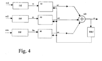
- Figure 4 shows the baseband combiner of the present invention.
- the demodulators DE which contain noise filters, the individual synchronism recovery circuits and the analog/digital converters, and can also conveniently comprise an adaptive equalizer and/or all which the designer considers necessary to include to provide the demodulated and possibly equalized overall signal. This is the known art and non-limitative of the constructive method for the stated demodulators, which will therefore not be further specified.
- each demodulator tries to counteract individual distortions to the limit of its possibilities without any benefit from the downstream combiner, from which it has to be independent. The result is that normally its output can be insufficiently equalized and unable to provide reconstructed symbols able to give reliable decisions.
- Each demodulator could in fact sample with a time phase difference with respect to the others, even though the signals are mutually synchronous, and a time slip could occur between one signal and another.
- the demodulators DE are connected to their respective 4D (four dimension) equalizers which correspond to a transversal structure with adaptive complex coefficients
- the equalizers 4D feed the signals se1 , se2, sen to an adder node AD. At its output the combined signal sc is fed to a device ERC for error calculation, the output of which is connected to the equalizers 4D.
- the device ERC can comprise a decision circuit, for example of threshold type.
- each signal requires its optimum sampling time given by the type of disturbance suffered when it has to be individually equalized, it must be also possible to produce a combination which is optimal.
- the combination must therefore be optimised even without imposing constraints between the combiner and the individual clock recoveries.
- the two or more demodulated signals are in any case sampled on the basis of their own distortion; to be able to efficiently combine them, the concurrent signals must be presented to the combiner with an impulse response suitable to make their combination efficient.
- the respective constellations provided by the demodulators must be mutually rotated and amplitude controlled in accordance with the combination optimum.
- control functional for the combination optimum use can be made of the known method of minimizing the mean square error at the decision circuit, recalculating the impulse response through the adaptive equalizers 4D.
- equalizers can be of the simple classical single-spaced structure, i.e. not FSE, but processing a single sample per symbol period. This fact, in contrast to Figure 1 , is important in that the demodulator which precedes them does not have to process the signal at higher sampling rate, which would increase the cost. Moreover said equalizers 4D do not require a large number of coefficients. With no more than 7 complex coefficients excellent results are obtained (even 10 dB of signal/noise ratio improvement in the case of a transmission channel with strong intersymbol distortion), so maintaining a low cost implementation.
- err is the calculation error at time (n+1)T; this operation is to be repeated for each signal sn.
- the position index m has been omitted, hence meaning that the updating of the coefficient at position m uses the sample of the time delay position m of the signal s, in accordance with the known equalizer art.
- the subscript n means the sampling time n.
- the combined signal is hence the sum of all the signals sen (i.e. all the n concurrent signals) as in Figure 4 .
- the combined signal sc is then fed to a decision circuit, not indicated in the figures. This calculates the error err on which the functional is based, to be used for updating the coefficients.
- radio link conceived in this manner is susceptible to numerous modifications and variants, all falling within the scope of the inventive concept; moreover all details can be replaced by technically equivalent elements.
Priority Applications (1)
| Application Number | Priority Date | Filing Date | Title |
|---|---|---|---|
| EP07013460A EP2015468A1 (en) | 2007-07-10 | 2007-07-10 | Baseband combiner for digital radio links |
Applications Claiming Priority (1)
| Application Number | Priority Date | Filing Date | Title |
|---|---|---|---|
| EP07013460A EP2015468A1 (en) | 2007-07-10 | 2007-07-10 | Baseband combiner for digital radio links |
Publications (1)
| Publication Number | Publication Date |
|---|---|
| EP2015468A1 true EP2015468A1 (en) | 2009-01-14 |
Family
ID=38961224
Family Applications (1)
| Application Number | Title | Priority Date | Filing Date |
|---|---|---|---|
| EP07013460A Withdrawn EP2015468A1 (en) | 2007-07-10 | 2007-07-10 | Baseband combiner for digital radio links |
Country Status (1)
| Country | Link |
|---|---|
| EP (1) | EP2015468A1 (sv) |
Cited By (3)
| Publication number | Priority date | Publication date | Assignee | Title |
|---|---|---|---|---|
| ITBG20090013A1 (it) * | 2009-04-02 | 2010-10-03 | Siae Microelettronica Spa | Sistema di protezione per ponti radio digitali a modulazione adattativa operanti in diversita' |
| CN102082749A (zh) * | 2010-12-24 | 2011-06-01 | 西安空间无线电技术研究所 | 一种均衡器的权系数更新装置及方法 |
| CN106301489A (zh) * | 2015-06-26 | 2017-01-04 | 深圳市中兴微电子技术有限公司 | 链路均衡方法及装置 |
Citations (3)
| Publication number | Priority date | Publication date | Assignee | Title |
|---|---|---|---|---|
| US3879664A (en) * | 1973-05-07 | 1975-04-22 | Signatron | High speed digital communication receiver |
| EP0631399B1 (en) * | 1993-06-25 | 2002-03-13 | Nec Corporation | Method and apparatus for interference cancellation and adaptive equalisation in diversity reception |
| WO2004049595A1 (en) * | 2002-11-27 | 2004-06-10 | Koninklijke Philips Electronics N.V. | Low complexity equalizer for radio receiver |
-
2007
- 2007-07-10 EP EP07013460A patent/EP2015468A1/en not_active Withdrawn
Patent Citations (3)
| Publication number | Priority date | Publication date | Assignee | Title |
|---|---|---|---|---|
| US3879664A (en) * | 1973-05-07 | 1975-04-22 | Signatron | High speed digital communication receiver |
| EP0631399B1 (en) * | 1993-06-25 | 2002-03-13 | Nec Corporation | Method and apparatus for interference cancellation and adaptive equalisation in diversity reception |
| WO2004049595A1 (en) * | 2002-11-27 | 2004-06-10 | Koninklijke Philips Electronics N.V. | Low complexity equalizer for radio receiver |
Cited By (6)
| Publication number | Priority date | Publication date | Assignee | Title |
|---|---|---|---|---|
| ITBG20090013A1 (it) * | 2009-04-02 | 2010-10-03 | Siae Microelettronica Spa | Sistema di protezione per ponti radio digitali a modulazione adattativa operanti in diversita' |
| EP2237463A1 (en) * | 2009-04-02 | 2010-10-06 | SIAE Microelettronica S.p.A. | Communication system with a diversity receiver operating with adaptive modulation |
| CN102082749A (zh) * | 2010-12-24 | 2011-06-01 | 西安空间无线电技术研究所 | 一种均衡器的权系数更新装置及方法 |
| CN102082749B (zh) * | 2010-12-24 | 2014-01-15 | 西安空间无线电技术研究所 | 一种均衡器的权系数更新装置及方法 |
| CN106301489A (zh) * | 2015-06-26 | 2017-01-04 | 深圳市中兴微电子技术有限公司 | 链路均衡方法及装置 |
| CN106301489B (zh) * | 2015-06-26 | 2019-10-18 | 深圳市中兴微电子技术有限公司 | 链路均衡方法及装置 |
Similar Documents
| Publication | Publication Date | Title |
|---|---|---|
| EP3198820B1 (en) | Linear equalization for use in low latency high speed communication systems | |
| US5353307A (en) | Automatic simulcast alignment | |
| EP0844765B1 (en) | Multicarrier receiver with an antenna array | |
| JP5317021B2 (ja) | 無線通信システム、受信装置、送信装置、無線通信方法、受信方法、及び送信方法 | |
| JP4544915B2 (ja) | 受信装置及びアナログ・ディジタル変換装置 | |
| EP2247012A1 (en) | Optical ofdm receiver, optical transmission system, subcarrier separation circuit, and subcarrier separation method | |
| EP0771084A1 (en) | Time diversity transmission-reception system | |
| US20040192215A1 (en) | Linear single-antenna interference cancellation receiver | |
| US4757319A (en) | Adaptive depolarization-interference-compensator | |
| US6205170B1 (en) | Transmission/reception unit with bidirectional equalization | |
| US7046753B2 (en) | Interference canceller with fast phase adaptation | |
| EP0477183B1 (en) | Space-diversity digital radio mobile receiver and relevant process | |
| EP2129026A1 (en) | Radio transmission method and interference compensation method | |
| WO2017183631A1 (ja) | Los-mimo復調装置、通信装置、los-mimo伝送システム、los-mimo復調方法及びプログラム | |
| US20130010810A1 (en) | Ingress Suppression for Communication Systems | |
| EP2015468A1 (en) | Baseband combiner for digital radio links | |
| US7130605B2 (en) | Method and device for synchronization and cancellation of a plurality on interfering signals in radio transmission with frequency reuse | |
| EP1708381B1 (en) | Cross-polarization transmission system with asynchronous receivers | |
| EP2237463B1 (en) | Communication system with a diversity receiver operating with adaptive modulation | |
| EP0902556A2 (en) | Telecommunication system and method using radio link | |
| JPH07154129A (ja) | Lms方式のアダプティブアレイアンテナ装置 | |
| KR100736602B1 (ko) | Vsb/qam 겸용 채널 등화기 | |
| EP1111837B1 (en) | Timing recovery method and device for telecommunications systems | |
| CN113746765B (zh) | Uddf水声通信协作方法及多分支合并与均衡频域联合实现方法 | |
| KR100739560B1 (ko) | Vsb/qam 겸용 다용도 채널 등화기 |
Legal Events
| Date | Code | Title | Description |
|---|---|---|---|
| PUAI | Public reference made under article 153(3) epc to a published international application that has entered the european phase |
Free format text: ORIGINAL CODE: 0009012 |
|
| 17P | Request for examination filed |
Effective date: 20080519 |
|
| AK | Designated contracting states |
Kind code of ref document: A1 Designated state(s): AT BE BG CH CY CZ DE DK EE ES FI FR GB GR HU IE IS IT LI LT LU LV MC MT NL PL PT RO SE SI SK TR |
|
| AX | Request for extension of the european patent |
Extension state: AL BA HR MK RS |
|
| 17Q | First examination report despatched |
Effective date: 20090408 |
|
| AKX | Designation fees paid |
Designated state(s): AT BE BG CH CY CZ DE DK EE ES FI FR GB GR HU IE IS IT LI LT LU LV MC MT NL PL PT RO SE SI SK TR |
|
| STAA | Information on the status of an ep patent application or granted ep patent |
Free format text: STATUS: THE APPLICATION IS DEEMED TO BE WITHDRAWN |
|
| 18D | Application deemed to be withdrawn |
Effective date: 20140920 |