EP0807790A2 - Method and system for prepairing sanitary hot water - Google Patents
Method and system for prepairing sanitary hot water Download PDFInfo
- Publication number
- EP0807790A2 EP0807790A2 EP97107971A EP97107971A EP0807790A2 EP 0807790 A2 EP0807790 A2 EP 0807790A2 EP 97107971 A EP97107971 A EP 97107971A EP 97107971 A EP97107971 A EP 97107971A EP 0807790 A2 EP0807790 A2 EP 0807790A2
- Authority
- EP
- European Patent Office
- Prior art keywords
- heat exchanger
- temperature
- fluid
- circuit
- temperature sensor
- Prior art date
- Legal status (The legal status is an assumption and is not a legal conclusion. Google has not performed a legal analysis and makes no representation as to the accuracy of the status listed.)
- Granted
Links
- XLYOFNOQVPJJNP-UHFFFAOYSA-N water Substances O XLYOFNOQVPJJNP-UHFFFAOYSA-N 0.000 title claims abstract description 79
- 238000000034 method Methods 0.000 title claims description 31
- 239000012530 fluid Substances 0.000 claims abstract description 49
- 230000007423 decrease Effects 0.000 claims description 2
- 238000009413 insulation Methods 0.000 claims description 2
- 230000001105 regulatory effect Effects 0.000 claims description 2
- 238000010438 heat treatment Methods 0.000 description 6
- 239000008236 heating water Substances 0.000 description 6
- 230000000694 effects Effects 0.000 description 3
- 238000007726 management method Methods 0.000 description 2
- 239000002356 single layer Substances 0.000 description 2
- 238000013517 stratification Methods 0.000 description 2
- 235000006506 Brasenia schreberi Nutrition 0.000 description 1
- 230000004913 activation Effects 0.000 description 1
- 230000001419 dependent effect Effects 0.000 description 1
- 238000010586 diagram Methods 0.000 description 1
- 239000003651 drinking water Substances 0.000 description 1
- 235000020188 drinking water Nutrition 0.000 description 1
- 230000002349 favourable effect Effects 0.000 description 1
- 239000013505 freshwater Substances 0.000 description 1
- 238000005338 heat storage Methods 0.000 description 1
- 239000008235 industrial water Substances 0.000 description 1
- 238000009434 installation Methods 0.000 description 1
- 239000010410 layer Substances 0.000 description 1
- 238000012423 maintenance Methods 0.000 description 1
- 230000004044 response Effects 0.000 description 1
- 230000000717 retained effect Effects 0.000 description 1
- 230000000630 rising effect Effects 0.000 description 1
- 238000010079 rubber tapping Methods 0.000 description 1
Images
Classifications
-
- F—MECHANICAL ENGINEERING; LIGHTING; HEATING; WEAPONS; BLASTING
- F24—HEATING; RANGES; VENTILATING
- F24D—DOMESTIC- OR SPACE-HEATING SYSTEMS, e.g. CENTRAL HEATING SYSTEMS; DOMESTIC HOT-WATER SUPPLY SYSTEMS; ELEMENTS OR COMPONENTS THEREFOR
- F24D19/00—Details
- F24D19/10—Arrangement or mounting of control or safety devices
- F24D19/1006—Arrangement or mounting of control or safety devices for water heating systems
- F24D19/1066—Arrangement or mounting of control or safety devices for water heating systems for the combination of central heating and domestic hot water
- F24D19/1069—Arrangement or mounting of control or safety devices for water heating systems for the combination of central heating and domestic hot water regulation in function of the temperature of the domestic hot water
Definitions
- the invention relates to an arrangement and a method for providing hot domestic water with a primary circuit with a fluid, a device providing hot or hot fluid and a conveying device for the fluid, a secondary circuit for the domestic water to be heated, a heat exchanger for heat transfer from the fluid of the primary circuit on the process water in the secondary circuit, a control device for the conveyor and a temperature sensor in the primary or secondary circuit.
- the hot domestic water is conventionally provided by means of a heating source in a domestic water storage tank, a so-called boiler, which also takes on the task of temporarily storing energy.
- This fluid is usually also water, but for example the water of a heating system, which is not intended for normal consumption or use.
- a process water queue runs through a heating water storage tank, during which process hot water is to be reheated via an assigned heating device.
- a temperature sensor is arranged in the thermally conductive contact with the hot water coil in the area where the hot water coil flows into the heating water tank. After the start of the tap, cool fresh water flows through exactly this junction area, and the resulting small temperature drop is transferred to the temperature sensor, which can thus be used to control the heating device.
- the process water is heated with the help of an external heat exchanger as a water heater.
- the fluid or heating water is pumped in a primary circuit through the heat exchanger, which heats the process water in the secondary circuit.
- Cold water is thus fed to the heat exchanger in the secondary circuit and brought there to the desired useful temperature by transferring the heat from the heating water from the heat generator through the heat exchanger to the process water.
- the hot water is available in a heated form.
- So-called stratified superchargers are particularly suitable as sources or stores for the hot fluid or heating water.
- the hotter amounts of water or fluid are layered on top of one another in a storage vessel.
- the primary circuit removes hot fluid from the top of the storage vessel, it flows through the heat exchanger mentioned and is then cooled again and is then stratified in a region of the storage vessel corresponding to the temperature between the amounts of water or fluid located there.
- a control device In order to be able to provide a reasonably constant water temperature for the process water, a control device can be provided.
- Such a control device is known for example from CH-PS 285 708; a temperature sensor is provided there, which is provided either in the primary circuit or also in the secondary circuit and acts on a three-way valve and thus regulates the primary-side temperature in the heat exchanger by changing the mixing ratio of the heating water in the primary circuit.
- the object of the invention is to propose an arrangement and a method for providing hot industrial water which does not require such flow monitors and at the same time creates an inexpensive control option.
- a first temperature sensor is arranged both in the primary circuit in the heat exchanger or in the line on the outlet side with respect to the heat exchanger and in the secondary circuit in the heat exchanger or in the second line temperature sensor in the outlet side with respect to the heat exchanger, and in that the control device has a circuit which switches on the conveying device when the temperature drops below a desired value and / or a temperature gradient amount exceeding a desired value at the second temperature sensor and switches off the conveying device at the first temperature sensor when the temperature increases above a desired value and / or when the temperature gradient exceeds a desired value.
- the object is achieved in that the temperature is measured both in the primary circuit in the heat exchanger or in the line on the outlet side with respect to the heat exchanger and in the secondary circuit in the heat exchanger or in the line on the outlet side with respect to the heat exchanger, and in that the temperature drops below a setpoint and / or via a setpoint increasing temperature gradient in the heat exchanger or in the line leading away from the heat exchanger in the secondary circuit, the conveying device begins to convey the fluid in the primary circuit, and that when the setpoint temperature rises and / or the setpoint temperature gradient increases in the heat exchanger or in the line away from the heat exchanger in the primary circuit, the delivery of the fluid in the primary circuit is ended.
- the temperature sensor in the process water circuit is particularly preferably arranged directly at the outlet of the heat exchanger in the secondary circuit. If the tap in the hot water pipe is opened after a previous standstill and hot water is requested, the hot water begins to flow in the secondary circuit.
- the temperature which is initially at the level of the heat exchanger, i.e. at a relatively high level, begins to drop quite spontaneously when the water from the cold water supply of the process water runs through the heat exchanger, whose heat reserve naturally decreases.
- This falling temperature is immediately recognized by the temperature sensor. In one variant, this can be done in that this temperature falls below a desired value; in a preferred variant, this is simply determined by the temperature gradient.
- the latter also has the advantage that when the control system is started up with a cold store (initial start-up), the conveyor device is not switched on, even though a setpoint is undershot.
- the conveyor does not switch off yet, as process water continues to be withdrawn and there is therefore still a need for heat supply.
- the temperature gradient on this second temperature sensor in the secondary circuit is now very low or fluctuates around a zero value and the temperature is therefore constant and also above the setpoint, this is not a switch-on criterion: the conveyor is still running.
- the thermal energy of the hot fluid is no longer released to the process water in the primary circuit, since the process water is already at the appropriate temperature and requires no additional supply.
- the fluid in the primary circuit flows through the heat exchanger without having completely lost its heat, which leads to a very rapid temperature rise in the region of the first temperature sensor on the output side of the heat exchanger in the primary circuit.
- This rising temperature can be used as a switch-off criterion either by exceeding a setpoint or also by recognizing a temperature gradient, and thus stops the conveyor.
- a particularly quick response is ensured if the respective temperature sensors are provided on the heat exchanger on the output side. In certain applications, it may even make sense to provide the temperature sensors inside the heat exchanger. The closer the temperature sensors are to the heat exchanger, the faster they can detect any changes in temperature and thus prevent the creation of undesired cold water areas in the hot water supply.
- the conveying device in particular a pump, in the primary circuit should, if possible, be arranged in the line leading away from the heat exchanger, that is to say in its line on the outlet side.
- colder primary fluid flows through the conveying device, particularly when it is at a standstill, which is more favorable for its durability and ease of maintenance.
- the first temperature sensor is arranged between the heat exchanger and the conveyor.
- the arrangement and the method can be used particularly well if the warm or hot fluid is provided by a buffer store, but the flow of a boiler, a district heating network or the like are also suitable.
- a third temperature sensor is also provided, which is located either in the buffer store or in the line from the buffer store to the heat exchanger.
- the control device has a further circuit with which the temperature determined by the third temperature sensor is used when determining the setpoint value of the temperature at the second temperature sensor. In this way, the case can be taken into account that there may not be enough warm or hot fluid in the buffer storage, for example when the system is started up for the first time or simply after considerable consumption has already taken place. It can then be prevented by lowering the setpoint values of the temperatures at the second temperature sensor that the buffer memory continuously releases further contents without it being possible at all to achieve the setpoint values otherwise desired by the control device.
- the invention makes it possible, by observing the storage tank temperature in relation to the desired water temperature, to prevent the storage tank from mixing due to an excessive flow rate of the primary circuit and to maintain standby operation.
- a diagram of the temperature curve at various measuring points on the heat exchanger and storage tank is considered in relation to a typical user behavior, ie different amounts of water taken off and the turning on and off of the tap were simulated. If the heat storage tank does not have the temperature required for the hot water setpoint temperature, the hot water setpoint temperature is reduced from the storage tank temperature adjustable difference is calculated. The hot water target temperature is therefore not an absolute value, but - if the storage tank temperature is too low - also dependent on this.
- the pump would run fully in order to get as close as possible to the set hot water setpoint with the maximum available energy. Due to the maximum primary flow, the primary return temperature rises unnecessarily high. This can lead to rapid disintegration or temperature stratification in the storage tank, which results in a further drop in the storage tank temperature.
- the actual hot water setpoint can therefore be calculated again from the storage tank temperature minus the set difference. This prevents the primary flow from being exceeded above a desired limit value and the storage stratification is retained under all operating conditions.
- a pump runtime element is useful in order to bridge temperature fluctuations after switching on, which could be regarded as a switch-off criterion. Furthermore, it is normally chosen so that enough thermal energy is pumped into the system to bring the heat exchanger and thus the hot water outlet to the required temperature.
- the conveying device is a speed-controlled pump and the regulating device has a circuit which, depending on the temperature gradient at the second temperature sensor, also regulates the conveying speed of the conveying device, that is to say, for example, the speed.
- one or both temperature sensors are arranged within the insulation of the buffer store. This allows the heat exchanger to reach the target temperature are kept, simply by heat conduction automatically from the buffer storage.
- the control device can also use a special combination of different process stages.
- a start-up control program can be run for a limited period of time, for example 30 seconds, which provides for a constantly predetermined pump speed, or a special P-I-D setting that can react very quickly to changes in temperature. In this way, the target temperature can be maintained and cold water holes avoided at the start of hot water tapping.
- the use of the temperature gradient amount as a switch-on criterion has also proven to be useful for the following reason: After opening the hot water tap, the hot water in the heat exchanger is at a slightly higher level than the thermal sensor on the output side of the heat exchanger can detect a short distance away.
- One of the effects of this is that, due to convection currents on the primary side in the heat exchanger, a very slightly higher temperature is set there than can be the case with a non-running secondary circuit in the process water. This effect is usually hardly measurable.
- control device determines the amount of the temperature gradient due to its falling and can react accordingly.
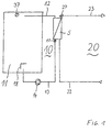
- the purely schematic illustration which shows only the most essential parts of the entire arrangement, shows a primary circuit 10 in the left half and a secondary circuit 20 in the right half.
- the primary circuit 10 begins on the left with a device that provides warm or hot fluid, here a buffer store 11. From this buffer store 11, a line 12 leads to a heat exchanger 5. After passing through the heat exchanger 5 and giving off the thermal energy in it, the fluid leads in the primary circuit 10 back via an outlet-side line 13 to the buffer store 11.
- a conveying device here a pump 14, is provided, between the heat exchanger 5 and the pump 14 a first temperature sensor 17 is arranged.
- the hot fluid is usually removed from the upper region of the buffer store 11, fed to the heat exchanger 5 and returned by the pump 14 to the lower region of the buffer store 11.
- a fluid single-layer device 18 which is only indicated schematically here, can be provided, for example a stratified charger according to EP 0 384 423 B1.
- hot fluid remains undisturbed in the upper region, where the line 12 also draws it off.
- Additional hot fluid or thermal energy for heating existing fluids can be provided by layering fluids heated by solar collectors and / or by installing burners (not shown in each case) or in another way.
- the secondary circuit 20 on the right side begins with a cold water supply line 22, with which cold process water (drinking water, wash water, etc.) is fed to the heat exchanger 5.
- the heat energy of the primary circuit 10 running in countercurrent is received in the heat exchanger 5.
- the process water leaves it again and flows through an outlet-side line 23 to the hot water withdrawal point.
- the promotion in the secondary circuit can take place, for example, in that the cold water supply takes place under pressure and the hot water withdrawal point by a tap may block this pressure.
- the temperature sensor 27 detects the hot water temperature as close as possible to the heat exchanger 5.
- the temperature sensors 17 and 27 report their values to a control device, not shown.
- a third temperature sensor 37 which records the temperature of the hot fluid in the upper region of the buffer store 11.
- the control device then controls the pump 14, on the one hand the switching on and off and on the other hand also the speed or conveying speed, if applicable.
Abstract
Description
Die Erfindung betrifft eine Anordnung und ein Verfahren zur Bereitstellung von warmem Brauchwasser mit einem Primärkreislauf mit einem Fluid, einer warmes oder heißes Fluid bereitstellenden Einrichtung und einer Fördereinrichtung für das Fluid, einem Sekundärkreislauf für das zu erwärmende Brauchwasser, einem Wärmetauscher zur Wärmeübertragung vom Fluid des Primärkreislaufs auf das Brauchwasser im Sekundärkreislauf, einer Regelungseinrichtung für die Fördereinrichtung und einem Temperaturfühler im Primär- oder Sekundärkreislauf.The invention relates to an arrangement and a method for providing hot domestic water with a primary circuit with a fluid, a device providing hot or hot fluid and a conveying device for the fluid, a secondary circuit for the domestic water to be heated, a heat exchanger for heat transfer from the fluid of the primary circuit on the process water in the secondary circuit, a control device for the conveyor and a temperature sensor in the primary or secondary circuit.
Die Bereitstellung vom warmem Brauchwasser erfolgt konventionell mittels einer Heizquelle in einem Brauchwasserspeicher, einem sogenannten Boiler, der dabei zugleich die Aufgabe der Energiezwischenspeicherung übernimmt.The hot domestic water is conventionally provided by means of a heating source in a domestic water storage tank, a so-called boiler, which also takes on the task of temporarily storing energy.
In vielen Fällen sinnvoll und auch bewährt ist es, hier eine Trennung des Brauchwassers einerseits und des eigentlich beheizten Fluides andererseits vorzunehmen. Dieses Fluid ist üblicherweise ebenfalls Wasser, aber beispielsweise das Wasser einer Heizungsanlage, das nicht für den üblichen Verzehr oder Gebrauch gedacht ist.In many cases it makes sense and is also proven to separate the process water on the one hand and the actually heated fluid on the other. This fluid is usually also water, but for example the water of a heating system, which is not intended for normal consumption or use.
In der DE 295 19 473 U1 wird ein Durchflußbrauchwassererwärmer vorgeschlagen. Bei diesem läuft eine Brauchwasserschlange durch einen Heizwasserspeicher, wobei während der Brauchwasserentnahme eine Nachheizung über eine zugeordnete Heizeinrichtung erfolgen soll. Um zu erkennen, daß eine Brauchwasserentnahme erfolgt, ist im Einmündungsbereich der Brauchwasserschlange in den Heizwasserspeicher ein Temperatursensor in gut wärmeleitendem Kontakt mit der Brauchwasserschlange angeordnet. Nach dem Zapfbeginn strömt kühles Frischwasser durch genau diesen Einmündungsbereich, und der dadurch entstehende geringe Temperaturabfall überträgt sich auf den Temperatursensor, der damit zur Steuerung der Heizeinrichtung dienen kann.DE 295 19 473 U1 proposes a flow water heater. In this case, a process water queue runs through a heating water storage tank, during which process hot water is to be reheated via an assigned heating device. In order to recognize that hot water is being drawn off, a temperature sensor is arranged in the thermally conductive contact with the hot water coil in the area where the hot water coil flows into the heating water tank. After the start of the tap, cool fresh water flows through exactly this junction area, and the resulting small temperature drop is transferred to the temperature sensor, which can thus be used to control the heating device.
In anderen Fällen wird das Brauchwasser mit Hilfe eines externen Wärmetauschers als Durchlauferhitzer erwärmt. Dabei wird das Fluid bzw. Heizungswasser in einem Primärkreislauf durch den Wärmetauscher gepumpt, der das Brauchwasser im Sekundärkreislauf erwärmt. Es wird also kaltes Wasser im Sekundärkreislauf dem Wärmetauscher zugeführt und dort auf die gewünschte Nutztemperatur gebracht, indem die Wärme aus dem Heizungswasser vom Wärmeerzeuger durch den Wärmetauscher auf das Brauchwasser übertragen wird. Nach Durchlaufen des Wärmetauschers steht das Brauchwasser in erwärmter Form zur Verfügung.In other cases, the process water is heated with the help of an external heat exchanger as a water heater. The fluid or heating water is pumped in a primary circuit through the heat exchanger, which heats the process water in the secondary circuit. Cold water is thus fed to the heat exchanger in the secondary circuit and brought there to the desired useful temperature by transferring the heat from the heating water from the heat generator through the heat exchanger to the process water. After passing through the heat exchanger, the hot water is available in a heated form.
Besonders geeignet als Quelle bzw. Speicher für das heiße Fluid bzw. Heizungswasser sind sogenannte Schichtenlader, wie sie etwa aus der EP 0 384 423 B1 bekannt sind. In ihnen sind in einem Speichergefäß oben die heißeren, unten die kühleren Wasser- bzw. Fluidmengen übereinandergeschichtet. Der Primärkreislauf entnimmt dem Speichergefäß oben heißes Fluid, dieses fließt durch den erwähnten Wärmetauscher und wird anschließend entsprechend abgekühlt wieder in einem der Temperatur entsprechenden Bereich des Speichergefäßes zwischen die dort befindlichen Wasser- bzw. Fluidmengen eingeschichtet.So-called stratified superchargers, as are known, for example, from EP 0 384 423 B1, are particularly suitable as sources or stores for the hot fluid or heating water. The hotter amounts of water or fluid are layered on top of one another in a storage vessel. The primary circuit removes hot fluid from the top of the storage vessel, it flows through the heat exchanger mentioned and is then cooled again and is then stratified in a region of the storage vessel corresponding to the temperature between the amounts of water or fluid located there.
Um eine einigermaßen konstante Wassertemperatur des Brauchwassers zur Verfügung stellen zu können, kann eine Regeleinrichtung vorgesehen werden.In order to be able to provide a reasonably constant water temperature for the process water, a control device can be provided.
Eine solche Regeleinrichtung ist beispielsweise aus der CH-PS 285 708 bekannt; dort ist ein Temperaturfühler vorgesehen, der entweder im Primärkreislauf oder aber auch im Sekundärkreislauf vorgesehen ist und auf einen Dreiwegehahn einwirkt und so über eine Änderung des Mischungsverhältnisses des Heizungswassers im Primärkreislauf die primärseitige Temperatur im Wärmetauscher regelt.Such a control device is known for example from CH-PS 285 708; a temperature sensor is provided there, which is provided either in the primary circuit or also in the secondary circuit and acts on a three-way valve and thus regulates the primary-side temperature in the heat exchanger by changing the mixing ratio of the heating water in the primary circuit.
Bei im übrigen gleicher Funktionsweise wird beispielsweise in der DE 40 35 115 C2 eine von einem Strömungswächter gesteuerte Drehzahlregelung der Pumpe im Primärkreislauf eingesetzt. Als Nachteil hat sich allerdings dabei die Verwendung eines Strömungswächters in der Brauchwasserleitung erwiesen. Strömungswächter erfordern erhebliche Anschaffungs- und Montagekosten und sind ausgesprochen fehleranfällig. An sich sollen die Strömungswächter aufgrund eines Durchflusses erkennen, ob Wasser strömt, mithin Brauchwasser entnommen wird, und davon abhängig Umwälzpumpen ein- bzw. ausschalten.With the rest of the same mode of operation, for example in DE 40 35 115 C2 a speed control of the pump controlled by a flow switch is used in the primary circuit. However, this has the disadvantage Proven use of a flow switch in the hot water pipe. Flow monitors require considerable acquisition and installation costs and are extremely prone to errors. As such, the flow monitors should recognize, based on a flow, whether water is flowing, and therefore process water is being drawn, and, depending on this, switch on or off the circulation pumps.
Aufgabe der Erfindung ist es, eine Anordnung und ein Verfahren zur Bereitstellung von warmem Brauchwasser vorzuschlagen, die ohne derartige Strömungswächter auskommt und gleichzeitig eine kostengünstige Regelungsmöglichkeit schafft.The object of the invention is to propose an arrangement and a method for providing hot industrial water which does not require such flow monitors and at the same time creates an inexpensive control option.
Diese Aufgabe wird bei einer Anordnung dadurch gelöst, daß sowohl im Primärkreislauf im Wärmetauscher oder in der bezüglich des Wärmetauschers ausgangsseitigen Leitung ein erster Temperaturfühler als auch im Sekundärkreislauf im Wärmetauscher oder in der bezüglich des Wärmetauschers ausgangsseitigen Leitung ein zweiter Temperaturfühler angeordnet ist, und daß die Regelungseinrichtung eine Schaltung aufweist, die bei unter einen Sollwert sinkender Temperatur und/oder einem einen Sollwert übersteigenden Temperaturgradientenbetrag am zweiten Temperaturfühler die Fördereinrichtung einschaltet und bei über einen Sollwert steigender Temperatur und/oder einem einen Sollwert übersteigenden Temperaturgradientenbetrag am ersten Temperaturfühler die Fördereinrichtung ausschaltet.This object is achieved in an arrangement in that a first temperature sensor is arranged both in the primary circuit in the heat exchanger or in the line on the outlet side with respect to the heat exchanger and in the secondary circuit in the heat exchanger or in the second line temperature sensor in the outlet side with respect to the heat exchanger, and in that the control device has a circuit which switches on the conveying device when the temperature drops below a desired value and / or a temperature gradient amount exceeding a desired value at the second temperature sensor and switches off the conveying device at the first temperature sensor when the temperature increases above a desired value and / or when the temperature gradient exceeds a desired value.
Bei einem Verfahren wird die Aufgabe dadurch gelöst, daß sowohl im Primärkreislauf im Wärmetauscher oder in der bezüglich des Wärmetauschers ausgangsseitigen Leitung als auch im Sekundärkreislauf im Wärmetauscher oder in der bezüglich des Wärmetauschers ausgangsseitigen Leitung die Temperatur gemessen wird, und daß bei unter einen Sollwert sinkender Temperatur und/oder über einen Sollwert steigenden Temperaturgradienten im Wärmetauscher oder in der vom Wärmetauscher wegführenden Leitung im Sekundärkreislauf die Fördereinrichtung das Fluid im Primärkreislauf zu fördern beginnt, und daß bei über einen Sollwert steigender Temperatur und/oder über einen Sollwert steigendem Temperaturgradientenbetrag im Wärmetauscher oder in der Leitung vom Wärmetauscher weg im Primärkreislauf die Förderung des Fluides im Primärkreislauf beendet wird.In a method, the object is achieved in that the temperature is measured both in the primary circuit in the heat exchanger or in the line on the outlet side with respect to the heat exchanger and in the secondary circuit in the heat exchanger or in the line on the outlet side with respect to the heat exchanger, and in that the temperature drops below a setpoint and / or via a setpoint increasing temperature gradient in the heat exchanger or in the line leading away from the heat exchanger in the secondary circuit, the conveying device begins to convey the fluid in the primary circuit, and that when the setpoint temperature rises and / or the setpoint temperature gradient increases in the heat exchanger or in the line away from the heat exchanger in the primary circuit, the delivery of the fluid in the primary circuit is ended.
Durch diese konsequente Verwendung von Temperaturfühlern und das Ermitteln von Temperaturen und/oder Temperaturgradienten kann vollständig auf alle Strömungswächter verzichtet werden.Through this consistent use of temperature sensors and the determination of temperatures and / or temperature gradients, all flow monitors can be completely dispensed with.
Gleichwohl ist es möglich, immer gleichbleibend die gewünschte Warmwassertemperatur (Brauchwassertemperatur) zur Verfügung zu stellen.Nevertheless, it is possible to always provide the desired hot water temperature (hot water temperature).
Betrachtet man zunächst das Einschaltkriterium für die Fördereinrichtung des Fluides, so wird dieses im wesentlichen von dem Temperaturfühler im Brauchwasserkreislauf bestimmt. Dieser Temperaturfühler wird besonders bevorzugt unmittelbar am Ausgang des Wärmetauschers im Sekundärkreislauf angeordnet. Wird nun nach vorherigem Stillstand der Wasserhahn in der Brauchwasserleitung geöffnet und Warmwasser verlangt, so beginnt das Brauchwasser im Sekundärkreislauf zu strömen. Die Temperatur, die zunächst noch auf dem Stand des Wärmetauschers, also auf relativ hohem Niveau, ist, beginnt recht spontan zu fallen, wenn das Wasser aus der Kaltwasserzufuhr des Brauchwassers durch den Wärmetauscher läuft, dessen Wärmereserve natürlich abnimmt.If you first consider the switch-on criterion for the fluid delivery device, this is essentially determined by the temperature sensor in the process water circuit. This temperature sensor is particularly preferably arranged directly at the outlet of the heat exchanger in the secondary circuit. If the tap in the hot water pipe is opened after a previous standstill and hot water is requested, the hot water begins to flow in the secondary circuit. The temperature, which is initially at the level of the heat exchanger, i.e. at a relatively high level, begins to drop quite spontaneously when the water from the cold water supply of the process water runs through the heat exchanger, whose heat reserve naturally decreases.
Diese sinkende Temperatur wird vom Temperaturfühler sofort erkannt. Dies kann bei einer Variante dadurch geschehen, daß diese Temperatur unter einen Sollwert fällt, bei einer bevorzugten Variante wird dies einfach durch den Temperaturgradienten festgestellt. Letzteres bietet zudem den Vorteil, daß bei einer Inbetriebnahme der Regelung bei kaltem Speicher (Erstinbetriebnahme) die Fördereinrichtung nicht eingeschaltet wird, obwohl ein Sollwert unterschritten wird.This falling temperature is immediately recognized by the temperature sensor. In one variant, this can be done in that this temperature falls below a desired value; in a preferred variant, this is simply determined by the temperature gradient. The latter also has the advantage that when the control system is started up with a cold store (initial start-up), the conveyor device is not switched on, even though a setpoint is undershot.
Eines dieser beiden Kriterien führt nun unverzüglich zur Einschaltung der Fördereinrichtung im Primärkreislauf, die jetzt heißes Fluid des Primärkreislaufs dem Wärmetauscher zuführt und so eine Wärmeübertragung innerhalb des Wärmetauschers von diesem Fluid auf das Brauchwasser ermöglicht.One of these two criteria now leads immediately to the activation of the conveyor in the primary circuit, which now supplies hot fluid from the primary circuit to the heat exchanger and thus enables heat transfer within the heat exchanger from this fluid to the process water.
Die Fördereinrichtung schaltet nun noch nicht ab, da weiterhin Brauchwasser entnommen wird und damit weiterhin Bedarf für Wärmezufuhr besteht. Zwar ist der Temperaturgradient an diesem zweiten Temperaturfühler im Sekundärkreislauf nun sehr gering oder schwankt um einen Nullwert und die Temperatur ist mithin konstant und auch oberhalb des Sollwertes, es geht hier jedoch gerade nicht um ein Einschaltkriterium: Die Fördereinrichtung läuft ja noch.The conveyor does not switch off yet, as process water continues to be withdrawn and there is therefore still a need for heat supply. Although the temperature gradient on this second temperature sensor in the secondary circuit is now very low or fluctuates around a zero value and the temperature is therefore constant and also above the setpoint, this is not a switch-on criterion: the conveyor is still running.
Wird jetzt jedoch die Brauchwasserentnahme beendet, so wird im Primärkreislauf die Wärmeenergie des heißen Fluides nicht mehr an das Brauchwasser abgegeben, da dieses bereits auf der entsprechenden Temperatur ist und keine zusätzliche Zufuhr benötigt. Infolgedessen strömt das Fluid in dem Primärkreislauf durch den Wärmetauscher hindurch, ohne seine Wärme ganz verloren zu haben, was zu einem sehr raschen Temperaturanstieg im Bereich des ersten Temperaturfühlers auf der Ausgangsseite des Wärmetauschers im Primärkreislauf führt. Diese steigende Temperatur kann entweder durch Überschreiten eines Sollwertes oder ebenfalls durch Erkennen eines Temperaturgradienten als Ausschaltkriterium genutzt werden und stoppt so die Fördereinrichtung.However, if the process water withdrawal is now stopped, the thermal energy of the hot fluid is no longer released to the process water in the primary circuit, since the process water is already at the appropriate temperature and requires no additional supply. As a result, the fluid in the primary circuit flows through the heat exchanger without having completely lost its heat, which leads to a very rapid temperature rise in the region of the first temperature sensor on the output side of the heat exchanger in the primary circuit. This rising temperature can be used as a switch-off criterion either by exceeding a setpoint or also by recognizing a temperature gradient, and thus stops the conveyor.
Ein besonders rasches Ansprechen wird gewährleistet, wenn die jeweiligen Temperaturfühler unmittelbar ausgangsseitig am Wärmetauscher vorgesehen sind. In bestimmten Anwendungsfällen kann es sogar sinnvoll sein, die Temperaturfühler noch innerhalb des Wärmetauschers vorzusehen. Je dichter die Temperaturfühler am Wärmetauscher sind, desto schneller können sie etwaige Temperaturänderungen erkennen und damit das Entstehen von ungewünschten Kaltwasserbereichen in der Warmwasserabgabe verhindern.A particularly quick response is ensured if the respective temperature sensors are provided on the heat exchanger on the output side. In certain applications, it may even make sense to provide the temperature sensors inside the heat exchanger. The closer the temperature sensors are to the heat exchanger, the faster they can detect any changes in temperature and thus prevent the creation of undesired cold water areas in the hot water supply.
Die Fördereinrichtung, insbesondere eine Pumpe, im Primärkreislauf sollte nach Möglichkeit in der vom Wärmetauscher wegführenden, also in seiner ausgangsseitigen Leitung angeordnet sein. Dies führt dazu, daß die Fördereinrichtung insbesondere im Stillstand eher von kälterem Primärfluid durchströmt wird, was für ihre Haltbarkeit und Wartungsfreundlichkeit günstiger ist. Dabei ist es besonders sinnvoll, wenn der erste Temperaturfühler zwischen dem Wärmetauscher und der Fördereinrichtung angeordnet ist.The conveying device, in particular a pump, in the primary circuit should, if possible, be arranged in the line leading away from the heat exchanger, that is to say in its line on the outlet side. As a result, colder primary fluid flows through the conveying device, particularly when it is at a standstill, which is more favorable for its durability and ease of maintenance. It is special useful if the first temperature sensor is arranged between the heat exchanger and the conveyor.
Die Anordnung und das Verfahren sind besonders dann gut einsetzbar, wenn das warme oder heiße Fluid von einem Pufferspeicher bereitgestellt wird, aber auch der Vorlauf eines Heizkessels, ein Fernwärmenetz oder ähnliches sind geeignet.The arrangement and the method can be used particularly well if the warm or hot fluid is provided by a buffer store, but the flow of a boiler, a district heating network or the like are also suitable.
Bei Einsatz in Zusammenhang mit einem Pufferspeicher ist es bevorzugt, wenn außerdem ein dritter Temperaturfühler vorgesehen ist, der sich entweder im Pufferspeicher oder in der Leitung vom Pufferspeicher zum Wärmetauscher befindet. Dabei besitzt die Regelungseinrichtung eine weitere Schaltung, mit der die von dem dritten Temperaturfühler ermittelte Temperatur bei der Festlegung des Sollwertes der Temperatur am zweiten Temperaturfühler herangezogen wird. Dadurch kann nämlich auch der Fall berücksichtigt werden, daß sich möglicherweise im Pufferspeicher gar nicht genügend warmes oder heißes Fluid befindet, beispielsweise beim allerersten Anfahren der Anlage oder auch einfach nach schon vorhergehendem erheblichem Verbrauch. Es kann dann durch Absenken der Sollwerte der Temperaturen am zweiten Temperaturfühler verhindert werden, daß der Pufferspeicher ständig weitere Inhalte abgibt, ohne daß es überhaupt möglich ist, die von der Regelungseinrichtung sonst angestrebten Sollwerte zu erreichen.When used in conjunction with a buffer store, it is preferred if a third temperature sensor is also provided, which is located either in the buffer store or in the line from the buffer store to the heat exchanger. The control device has a further circuit with which the temperature determined by the third temperature sensor is used when determining the setpoint value of the temperature at the second temperature sensor. In this way, the case can be taken into account that there may not be enough warm or hot fluid in the buffer storage, for example when the system is started up for the first time or simply after considerable consumption has already taken place. It can then be prevented by lowering the setpoint values of the temperatures at the second temperature sensor that the buffer memory continuously releases further contents without it being possible at all to achieve the setpoint values otherwise desired by the control device.
Weiter ist es durch die Erfindung möglich, durch Beobachtung der Speichertemperatur in Bezug auf die gewünschte Wassertemperatur, eine Durchmischung des Speichers in Folge einer zu großen Durchflußmenge des Primärkreislaufs zu verhindern und einen Bereitschaftsbetrieb aufrecht zu erhalten. Dafür wird ein Diagramm des Temperaturverlaufes an verschiedenen Meßpunkten am Wärmetauscher und Speicher in Bezug auf ein typisches Benutzerverhalten betrachtet, d.h. es wurden verschiedene Wasserabnahmemengen sowie das Auf- und Abdrehen des Wasserhahnes simuliert. Wenn der Wärmespeicher nicht die für die Warmwasser-Solltemperatur notwendige Temperatur besitzt, wird die Warmwasser-Solltemperatur aus der Speichertemperatur abzüglich einer einstellbaren Differenz berechnet. Die Warmwasser-Solltemperatur ist daher kein Absolutwert, sondern - wenn die Speichertemperatur zu niedrig ist - auch von dieser abhängig.Furthermore, the invention makes it possible, by observing the storage tank temperature in relation to the desired water temperature, to prevent the storage tank from mixing due to an excessive flow rate of the primary circuit and to maintain standby operation. For this purpose, a diagram of the temperature curve at various measuring points on the heat exchanger and storage tank is considered in relation to a typical user behavior, ie different amounts of water taken off and the turning on and off of the tap were simulated. If the heat storage tank does not have the temperature required for the hot water setpoint temperature, the hot water setpoint temperature is reduced from the storage tank temperature adjustable difference is calculated. The hot water target temperature is therefore not an absolute value, but - if the storage tank temperature is too low - also dependent on this.
Wenn die Speichertemperatur während des Betriebes unter das für die Warmwasser-Sollwertregelung erforderliche Temperaturniveau fällt, würde aber die Pumpe voll laufen, um mit der maximal erhältlichen Energie so nahe wie möglich an den eingestellten Warmwasser-Sollwert heranzukommen. Durch den maximalen primären Durchfluß steigt aber die Primär-Rücklauftemperatur unnötig hoch an. Es kann dadurch zu einem raschen Zerfall oder Temperaturschichtung im Speicher kommen, was ein weiteres Absinken der Speichertemperatur zur Folge hat. Daher kann der tatsächliche Warmwasser-Sollwert wieder aus der Speichertemperatur abzüglich der eingestellten Differenz berechnet werden. Dadurch wird ein Überschreiten des Primärdurchflusses über einen gewünschten Grenzwert vermieden und die Speicherschichtung bleibt unter allen Betriebsbedingungen erhalten.If, during operation, the storage tank temperature falls below the temperature level required for the hot water setpoint control, the pump would run fully in order to get as close as possible to the set hot water setpoint with the maximum available energy. Due to the maximum primary flow, the primary return temperature rises unnecessarily high. This can lead to rapid disintegration or temperature stratification in the storage tank, which results in a further drop in the storage tank temperature. The actual hot water setpoint can therefore be calculated again from the storage tank temperature minus the set difference. This prevents the primary flow from being exceeded above a desired limit value and the storage stratification is retained under all operating conditions.
Ein Pumpenlaufzeitglied ist sinnvoll, um nach dem Einschalten Temperaturschwankungen, die als Ausschaltkriterium angesehen werden könnten, zu überbrücken. Weiter wird es im Normalfall gerade so gewählt, daß genügend Wärmeenergie in das System gepumpt wird, um den Wärmetauscher und damit den Warmwasser-Austritt auf die erforderliche Temperatur zu bringen.A pump runtime element is useful in order to bridge temperature fluctuations after switching on, which could be regarded as a switch-off criterion. Furthermore, it is normally chosen so that enough thermal energy is pumped into the system to bring the heat exchanger and thus the hot water outlet to the required temperature.
Besonders bevorzugt ist es außerdem, wenn die Fördereinrichtung eine drehzahlgeregelte Pumpe ist und die Regelungseinrichtung eine Schaltung aufweist, die abhängig von dem Temperaturgradienten am zweiten Temperaturfühler auch die Fördergeschwindigkeit der Fördereinrichtung, also beispielsweise die Drehzahl, regelt.It is also particularly preferred if the conveying device is a speed-controlled pump and the regulating device has a circuit which, depending on the temperature gradient at the second temperature sensor, also regulates the conveying speed of the conveying device, that is to say, for example, the speed.
Besonders bevorzugt ist es ferner, wenn eine oder beide Temperaturfühler, vorzugsweise gemeinsam mit dem Wärmetauscher innerhalb der Isolierung des Pufferspeichers angeordnet sind. Dadurch kann der Wärmetauscher auf Solltemperatur gehalten werden, und zwar einfach durch Wärmeleitung automatisch vom Pufferspeicher aus.It is also particularly preferred if one or both temperature sensors, preferably together with the heat exchanger, are arranged within the insulation of the buffer store. This allows the heat exchanger to reach the target temperature are kept, simply by heat conduction automatically from the buffer storage.
Die Regelungseinrichtung kann auch eine spezielle Kombination aus verschiedenen Verfahrensstufen einsetzen. So kann für einen begrenzten Zeitraum von beispielsweise 30 Sekunden ein Anfahrregelprogramm gefahren werden, das eine konstant vorgegebene Drehzahl der Pumpe vorsieht, oder aber auch eine spezielle P-I-D-Einstellung, die sehr schnell auf Temperaturänderungen reagieren kann. Gerade dadurch kann schon am Beginn der Warmwasserzapfung die Solltemperatur eingehalten und Kaltwasserlöcher vermieden werden.The control device can also use a special combination of different process stages. For example, a start-up control program can be run for a limited period of time, for example 30 seconds, which provides for a constantly predetermined pump speed, or a special P-I-D setting that can react very quickly to changes in temperature. In this way, the target temperature can be maintained and cold water holes avoided at the start of hot water tapping.
Die Verwendung des Temperaturgradientenbetrages als Einschaltkriterium hat sich auch noch aus folgendem Grund als sinnvoll erwiesen: Nach dem Aufdrehen des Warmwasserhahnes befindet sich im Wärmetauscher das Brauchwasser auf einem geringfügig höheren Niveau als dies eine kurze Strecke weiter der Thermofühler auf der Ausgangsseite des Wärmetauschers feststellen kann. Dieser Effekt liegt unter anderem darin, daß aufgrund von Konvektionsströmungen auf der Primärseite im Wärmetauscher sich dort eine ganz leicht höhere Temperatur einstellt, als dies bei nichtlaufendem Sekundärkreislauf im Brauchwasser der Fall sein kann. Dieser Effekt ist normalerweise kaum meßbar. Er hat jedoch zur Folge, daß nach dem Aufdrehen des Wasserhahnes für einen kurzen Moment die Temperatur am zweiten Thermofühler im Sekundärkreislauf ansteigt, und zwar ganz geringfügig, da die etwas heißere Brauchwassermenge aus dem Wärmetauscher jetzt am Thermofühler vorbeiströmt. Dieser stellt mithin einen Temperaturgradienten fest; daß dieser positiv ist, spielt für den Betrag des Temperaturgradienten keine Rolle und führt damit in der Regelungseinrichtung dazu, daß die Fördereinrichtung eingeschaltet wird. Dies geschieht mithin zu einem Zeitpunkt, an dem die Gefahr eines Kaltwasserloches noch gar nicht entstanden ist, so daß noch viel schneller als bei Unterschreiten des Sollwertes der Temperatur (dem zweiten Einschaltkriterium) schon die Fördereinrichtung läuft und heißes Fluid im Primärkreislauf in den Wärmetauscher bringt.The use of the temperature gradient amount as a switch-on criterion has also proven to be useful for the following reason: After opening the hot water tap, the hot water in the heat exchanger is at a slightly higher level than the thermal sensor on the output side of the heat exchanger can detect a short distance away. One of the effects of this is that, due to convection currents on the primary side in the heat exchanger, a very slightly higher temperature is set there than can be the case with a non-running secondary circuit in the process water. This effect is usually hardly measurable. However, it does have the consequence that after turning the tap on for a brief moment, the temperature at the second thermocouple in the secondary circuit rises very slightly, since the somewhat hotter amount of hot water from the heat exchanger now flows past the thermocouple. This determines a temperature gradient; the fact that this is positive is irrelevant for the magnitude of the temperature gradient and thus leads in the control device to the fact that the conveyor device is switched on. This happens at a time when the risk of a cold water hole has not yet arisen, so that the conveyor is already running much faster than when the temperature falls below the setpoint (the second switch-on criterion) and brings hot fluid in the primary circuit into the heat exchanger.
Sollte dieser Effekt nicht eintreten, etwa deshalb, weil sich noch kein durch Konvektionseinfluß entstandenes geringfügig höheres Temperaturniveau im Wärmetauscher eingestellt hat, so stellt die Regelungseinrichtung jedoch auch so beim Temperaturgradienten dessen Betrag aufgrund seines Fallens fest und kann entsprechend reagieren.If this effect does not occur, for example because a slightly higher temperature level has not yet arisen in the heat exchanger due to the influence of convection, the control device also determines the amount of the temperature gradient due to its falling and can react accordingly.
Im folgenden wird anhand der Zeichnung ein Ausführungsbeispiel der Erfindung näher beschrieben. Es zeigt:
- Figur 1 eine Schema-Darstellung der Erfindung.
- Figure 1 is a schematic representation of the invention.
Die rein schematische, nur die wesentlichsten Teile der gesamten Anordnung zeigende Darstellung zeigt in der linken Hälfte einen Primärkreislauf 10, in der rechten Hälfte einen Sekundärkreislauf 20.The purely schematic illustration, which shows only the most essential parts of the entire arrangement, shows a primary circuit 10 in the left half and a
Der Primärkreislauf 10 beginnt links mit einer Einrichtung, die warmes oder heisses Fluid bereitstellt, hier einem Pufferspeicher 11. Von diesem Pufferspeicher 11 führt eine Leitung 12 zu einem Wärmetauscher 5. Nach dem Durchlaufen des Wärmetauschers 5 und der Abgabe der Wärmeenergie in demselben führt das Fluid in dem Primärkreislauf 10 zurück über eine ausgangsseitige Leitung 13 zum Pufferspeicher 11. In der ausgangsseitigen Leitung 13 ist eine Fördereinrichtung, hier eine Pumpe 14 vorgesehen, zwischen dem Wärmetauscher 5 und der Pumpe 14 ist ein erster Temperaturfühler 17 angeordnet.The primary circuit 10 begins on the left with a device that provides warm or hot fluid, here a
Üblicherweise wird das heiße Fluid aus dem oberen Bereich des Pufferspeichers 11 entnommen, dem Wärmetauscher 5 zugeführt und von der Pumpe 14 gefördert in den unteren Bereich des Pufferspeichers 11 zurückgegeben.The hot fluid is usually removed from the upper region of the
Zum Einschichten des abgekühlten Fluids in den Pufferspeicher 11 kann eine hier nur sehr schematisch angedeutete Fluideinschichtvorrichtung 18 vorgesehen werden, beispielsweise ein Schichtenlader gemäß der EP 0 384 423 B1. Im Pufferspeicher 11 bleibt damit ungestört heißes Fluid im oberen Bereich, dort, wo auch die Leitung 12 es jeweils abzieht. Zusätzliches heißes Fluid bzw. Wärmeenergie zur Erwärmung vorhandenen Fluids kann durch Einschichten von durch Solarkollektoren erwärmten Fluids und/oder durch Einbau von Brennern (jeweils nicht dargestellt) oder auch auf andere Weise bereitgestellt werden.To layer the cooled fluid into the
Der Sekundärkreislauf 20 auf der rechten Seite beginnt mit einer Kaltwasserzuleitung 22, mit der kaltes Brauchwasser (Trinkwasser, Waschwasser etc.) dem Wärmetauscher 5 zugeführt wird. In dem Wärmetauscher 5 wird die Wärmeenergie des im Gegenstrom laufenden Primärkreislaufs 10 aufgenommen. Nach Durchlaufen des Wärmetauschers 5 verläßt das Brauchwasser diesen wiederum und strömt durch eine ausgangsseitige Leitung 23 zum Warmwasserentnahmepunkt. Die Förderung im Sekundärkreislauf kann beispielsweise dadurch erfolgen, daß die Kaltwasserzufuhr unter Druck erfolgt und der Warmwasserentnahmepunkt durch einen Hahn diesen Druck gegebenenfalls sperrt.The
In der Leitung 23 für das Warmwasser bzw. eigentliche Brauchwasser befindet sich ein Temperaturfühler 27. Der Temperaturfühler 27 stellt also die Warmwassertemperatur möglichst dicht am Wärmetauscher 5 fest.There is a
Die Temperaturfühler 17 und 27 melden ihre Werte einer nicht dargestellten Regelungseinrichtung.The
Gleiches tut auch ein dritter Temperaturfühler 37, der die Temperatur des heissen Fluids im oberen Bereich des Pufferspeichers 11 aufnimmt.The same is done by a
Die Regelungseinrichtung steuert dann die Pumpe 14, und zwar einerseits das Ein- und Ausschalten und andererseits auch gegebenenfalls die Drehzahl bzw. Fördergeschwindigkeit.The control device then controls the
- 55
- WärmetauscherHeat exchanger
- 1010th
- PrimärkreislaufPrimary circuit
- 1111
- PufferspeicherBuffer storage
- 1212th
- Leitungmanagement
- 1313
- Leitungmanagement
- 1414
- Pumpepump
- 1717th
- TemperaturfühlerTemperature sensor
- 1818th
- FluideinschichtvorrichtungFluid single layer device
- 2020th
- SekundärkreislaufSecondary circuit
- 2222
- KaltwasserzuleitungCold water supply
- 2323
- Leitung zum WarmwasserentnahmepunktPipe to the hot water withdrawal point
- 2727
- TemperaturfühlerTemperature sensor
- 3737
- TemperaturfühlerTemperature sensor
Claims (12)
dadurch gekennzeichnet,
characterized,
dadurch gekennzeichnet,
characterized,
dadurch gekennzeichnet,
characterized,
dadurch gekennzeichnet,
characterized,
dadurch gekennzeichnet,
characterized,
dadurch gekennzeichnet,
characterized,
dadurch gekennzeichnet,
characterized,
dadurch gekennzeichnet,
characterized,
dadurch gekennzeichnet,
characterized,
dadurch gekennzeichnet,
characterized,
dadurch gekennzeichnet,
characterized,
dadurch gekennzeichnet,
characterized,
Applications Claiming Priority (2)
| Application Number | Priority Date | Filing Date | Title |
|---|---|---|---|
| DE19619566A DE19619566C1 (en) | 1996-05-15 | 1996-05-15 | Arrangement and method for providing hot domestic water |
| DE19619566 | 1996-05-15 |
Publications (3)
| Publication Number | Publication Date |
|---|---|
| EP0807790A2 true EP0807790A2 (en) | 1997-11-19 |
| EP0807790A3 EP0807790A3 (en) | 1998-11-18 |
| EP0807790B1 EP0807790B1 (en) | 2003-08-06 |
Family
ID=7794376
Family Applications (1)
| Application Number | Title | Priority Date | Filing Date |
|---|---|---|---|
| EP97107971A Expired - Lifetime EP0807790B1 (en) | 1996-05-15 | 1997-05-15 | Method and system for prepairing sanitary hot water |
Country Status (3)
| Country | Link |
|---|---|
| EP (1) | EP0807790B1 (en) |
| AT (1) | ATE246784T1 (en) |
| DE (1) | DE19619566C1 (en) |
Cited By (7)
| Publication number | Priority date | Publication date | Assignee | Title |
|---|---|---|---|---|
| EP0989372A2 (en) * | 1998-09-24 | 2000-03-29 | Gledhill (Water Storage) Limited | Improvements relating to heating apparatus |
| GB2368896A (en) * | 2000-11-11 | 2002-05-15 | Gledhill Water Storage | Heat exchange system, temperature sensor arrangement and operation |
| EP1906104A1 (en) * | 2006-09-18 | 2008-04-02 | Vaillant GmbH | Method for identifying the need to recharge a warm water boiler |
| EP2963350A1 (en) * | 2014-07-02 | 2016-01-06 | Markus Keitsch | System for the energy-saving operation of non-permanently used or non-permanently fully used heat exchangera in a conduit system, in particular for heating drinking water |
| DE102015113140A1 (en) | 2014-08-15 | 2016-02-18 | Solvis Gmbh & Co. Kg | Heating device with hot water tank and arranged therein water supply pipe |
| EP2503252A3 (en) * | 2011-03-18 | 2016-08-10 | Markus Keitsch | System for producing heated service water in a line system |
| CN110579023A (en) * | 2018-06-11 | 2019-12-17 | 芜湖美的厨卫电器制造有限公司 | Wall-mounted boiler water path circulation control method, device and system |
Families Citing this family (6)
| Publication number | Priority date | Publication date | Assignee | Title |
|---|---|---|---|---|
| DE29822245U1 (en) * | 1998-12-15 | 1999-07-15 | Limax Oel Gas Fernwaermetechni | Water heater for heating water buffer systems |
| DE10032714A1 (en) | 2000-07-07 | 2002-01-24 | Solvis Solarsysteme Gmbh | Arrangement and method for providing hot domestic water |
| DE102004018034B4 (en) * | 2004-04-14 | 2014-07-24 | Stiebel Eltron Gmbh & Co. Kg | Method for switching on a heat pump in connection with a hot water storage tank for heat pumps |
| DE102007028656B4 (en) * | 2007-06-21 | 2013-08-14 | Robert Bosch Gmbh | Boiler |
| DE102008029654A1 (en) | 2008-06-24 | 2009-12-31 | Solvis Gmbh & Co. Kg | Arrangement and method for providing warm drinking water with a heat exchanger |
| DE102016102718B4 (en) | 2016-02-16 | 2019-11-14 | Hoval Aktiengesellschaft | Domestic water heating system |
Citations (4)
| Publication number | Priority date | Publication date | Assignee | Title |
|---|---|---|---|---|
| CH285708A (en) | 1950-04-20 | 1952-09-30 | Gustavsbergs Fabriker Ab | System for heating domestic water. |
| EP0384423A1 (en) | 1989-02-23 | 1990-08-29 | SOLVIS Energiesysteme GmbH | Hot water accumulator with a heat exchanger for sanitary water as well as an exterior heating element and a distributor for the inflowing water |
| DE4035115A1 (en) | 1990-03-12 | 1991-09-19 | Sandler Energietechnik | Drawing off hot drinking water from heating installation - involves two separate circuits with pressurised fresh cold water supply to secondary circuit |
| DE29519473U1 (en) | 1995-12-08 | 1996-02-22 | Buderus Heiztechnik Gmbh | Hot water heater |
Family Cites Families (4)
| Publication number | Priority date | Publication date | Assignee | Title |
|---|---|---|---|---|
| NL8503345A (en) * | 1985-12-04 | 1987-07-01 | Nefit Nv | DEVICE FOR CONTROLLING A HOT WATER SUPPLY. |
| EP0621450A3 (en) * | 1993-04-23 | 1995-03-22 | Georg Lachenmeier | Method and apparatus for heating domestic hot water. |
| GB2293438A (en) * | 1994-09-20 | 1996-03-27 | Gledhill Water Storage | The control of water heating apparatus to prevent scalding |
| DE19512025C2 (en) * | 1995-03-31 | 1999-01-28 | Stiebel Eltron Gmbh & Co Kg | Gas heater |
-
1996
- 1996-05-15 DE DE19619566A patent/DE19619566C1/en not_active Expired - Fee Related
-
1997
- 1997-05-15 AT AT97107971T patent/ATE246784T1/en not_active IP Right Cessation
- 1997-05-15 EP EP97107971A patent/EP0807790B1/en not_active Expired - Lifetime
Patent Citations (4)
| Publication number | Priority date | Publication date | Assignee | Title |
|---|---|---|---|---|
| CH285708A (en) | 1950-04-20 | 1952-09-30 | Gustavsbergs Fabriker Ab | System for heating domestic water. |
| EP0384423A1 (en) | 1989-02-23 | 1990-08-29 | SOLVIS Energiesysteme GmbH | Hot water accumulator with a heat exchanger for sanitary water as well as an exterior heating element and a distributor for the inflowing water |
| DE4035115A1 (en) | 1990-03-12 | 1991-09-19 | Sandler Energietechnik | Drawing off hot drinking water from heating installation - involves two separate circuits with pressurised fresh cold water supply to secondary circuit |
| DE29519473U1 (en) | 1995-12-08 | 1996-02-22 | Buderus Heiztechnik Gmbh | Hot water heater |
Cited By (11)
| Publication number | Priority date | Publication date | Assignee | Title |
|---|---|---|---|---|
| EP0989372A2 (en) * | 1998-09-24 | 2000-03-29 | Gledhill (Water Storage) Limited | Improvements relating to heating apparatus |
| EP0989372A3 (en) * | 1998-09-24 | 2000-04-19 | Gledhill (Water Storage) Limited | Improvements relating to heating apparatus |
| GB2368896A (en) * | 2000-11-11 | 2002-05-15 | Gledhill Water Storage | Heat exchange system, temperature sensor arrangement and operation |
| GB2368896B (en) * | 2000-11-11 | 2003-10-29 | Gledhill Water Storage | Improvements relating to heating apparatus |
| EP1906104A1 (en) * | 2006-09-18 | 2008-04-02 | Vaillant GmbH | Method for identifying the need to recharge a warm water boiler |
| AT504286B1 (en) * | 2006-09-18 | 2008-09-15 | Vaillant Austria Gmbh | METHOD FOR LOADING A HOT WATER TANK |
| EP2503252A3 (en) * | 2011-03-18 | 2016-08-10 | Markus Keitsch | System for producing heated service water in a line system |
| EP2963350A1 (en) * | 2014-07-02 | 2016-01-06 | Markus Keitsch | System for the energy-saving operation of non-permanently used or non-permanently fully used heat exchangera in a conduit system, in particular for heating drinking water |
| DE102015113140A1 (en) | 2014-08-15 | 2016-02-18 | Solvis Gmbh & Co. Kg | Heating device with hot water tank and arranged therein water supply pipe |
| CN110579023A (en) * | 2018-06-11 | 2019-12-17 | 芜湖美的厨卫电器制造有限公司 | Wall-mounted boiler water path circulation control method, device and system |
| CN110579023B (en) * | 2018-06-11 | 2024-01-16 | 芜湖美的厨卫电器制造有限公司 | Control method, device and system for waterway circulation of wall-mounted furnace |
Also Published As
| Publication number | Publication date |
|---|---|
| ATE246784T1 (en) | 2003-08-15 |
| EP0807790B1 (en) | 2003-08-06 |
| DE19619566C1 (en) | 1997-11-27 |
| EP0807790A3 (en) | 1998-11-18 |
Similar Documents
| Publication | Publication Date | Title |
|---|---|---|
| EP0807790B1 (en) | Method and system for prepairing sanitary hot water | |
| DE3626510A1 (en) | HOT WATER HEATER CONTROL ARRANGEMENT AND METHOD | |
| DE3012308A1 (en) | CONTROL SYSTEM FOR AN ABSORPTION REFRIGERATOR, ABSORPTION REFRIGERATOR AND METHOD FOR THE OPERATION THEREOF | |
| EP2416073A2 (en) | Method and device for heating a fluid in a buffer store | |
| DE3714261C1 (en) | Condensing boiler and method for its operation | |
| DE2843929A1 (en) | ARRANGEMENT FOR CONTROLLING THE ROOM TEMPERATURE | |
| DE19859364C2 (en) | Heat supply system with peak load limitation | |
| EP1170554B1 (en) | System and method for preparing hot sanitary water | |
| EP0892223B1 (en) | Control and command system for a heating system | |
| EP2667104B1 (en) | System and method for warming drinking water | |
| DE2606535A1 (en) | TEMPERATURE SYSTEM | |
| DE19810416B4 (en) | Heating or cooling system with at least one heat or cold source | |
| EP2372260B1 (en) | Method for heating water according to the circulation principle and water heating system | |
| DE3620929A1 (en) | Method and device for controlling at least one heating installation | |
| DE3030565A1 (en) | Boiler for domestic heating systems - has burner connected to and regulated by room temp. control using three=way valve | |
| WO1997034111A1 (en) | Modulating solar-power regulator | |
| WO2003023288A1 (en) | Central heating installation | |
| EP4259978A1 (en) | Method for operating a heat pump | |
| EP0192225A2 (en) | Method and apparatus for space temperature regulation | |
| DE19824543C1 (en) | Circulating pump regulation in solar collector circuit | |
| AT507569B1 (en) | METHOD FOR HEATING HOT WATER | |
| DE102004042866B4 (en) | Drainback solar system | |
| AT414272B (en) | LAYERS MEMORY | |
| DE102018213258A1 (en) | Method and device for controlling a heating system | |
| DE19824034C2 (en) | Domestic water heating system |
Legal Events
| Date | Code | Title | Description |
|---|---|---|---|
| PUAI | Public reference made under article 153(3) epc to a published international application that has entered the european phase |
Free format text: ORIGINAL CODE: 0009012 |
|
| AK | Designated contracting states |
Kind code of ref document: A2 Designated state(s): AT CH DK ES FR GB GR IT LI NL PT SE |
|
| PUAL | Search report despatched |
Free format text: ORIGINAL CODE: 0009013 |
|
| AK | Designated contracting states |
Kind code of ref document: A3 Designated state(s): AT CH DK ES FR GB GR IT LI NL PT SE |
|
| 17P | Request for examination filed |
Effective date: 19990517 |
|
| RAP1 | Party data changed (applicant data changed or rights of an application transferred) |
Owner name: SOLVIS SOLARSYSTEME GMBH |
|
| 17Q | First examination report despatched |
Effective date: 20010619 |
|
| GRAH | Despatch of communication of intention to grant a patent |
Free format text: ORIGINAL CODE: EPIDOS IGRA |
|
| GRAH | Despatch of communication of intention to grant a patent |
Free format text: ORIGINAL CODE: EPIDOS IGRA |
|
| RAP1 | Party data changed (applicant data changed or rights of an application transferred) |
Owner name: SOLVIS GMBH & CO. KG |
|
| GRAA | (expected) grant |
Free format text: ORIGINAL CODE: 0009210 |
|
| AK | Designated contracting states |
Designated state(s): AT CH DK ES FR GB GR IT LI NL PT SE |
|
| PG25 | Lapsed in a contracting state [announced via postgrant information from national office to epo] |
Ref country code: NL Free format text: LAPSE BECAUSE OF FAILURE TO SUBMIT A TRANSLATION OF THE DESCRIPTION OR TO PAY THE FEE WITHIN THE PRESCRIBED TIME-LIMIT Effective date: 20030806 Ref country code: GB Free format text: LAPSE BECAUSE OF FAILURE TO SUBMIT A TRANSLATION OF THE DESCRIPTION OR TO PAY THE FEE WITHIN THE PRESCRIBED TIME-LIMIT Effective date: 20030806 Ref country code: FR Free format text: LAPSE BECAUSE OF FAILURE TO SUBMIT A TRANSLATION OF THE DESCRIPTION OR TO PAY THE FEE WITHIN THE PRESCRIBED TIME-LIMIT Effective date: 20030806 |
|
| REG | Reference to a national code |
Ref country code: GB Ref legal event code: FG4D Free format text: NOT ENGLISH |
|
| REG | Reference to a national code |
Ref country code: CH Ref legal event code: EP |
|
| REG | Reference to a national code |
Ref country code: CH Ref legal event code: NV Representative=s name: KATZAROV S.A. |
|
| PG25 | Lapsed in a contracting state [announced via postgrant information from national office to epo] |
Ref country code: SE Free format text: LAPSE BECAUSE OF FAILURE TO SUBMIT A TRANSLATION OF THE DESCRIPTION OR TO PAY THE FEE WITHIN THE PRESCRIBED TIME-LIMIT Effective date: 20031106 Ref country code: GR Free format text: LAPSE BECAUSE OF FAILURE TO SUBMIT A TRANSLATION OF THE DESCRIPTION OR TO PAY THE FEE WITHIN THE PRESCRIBED TIME-LIMIT Effective date: 20031106 Ref country code: DK Free format text: LAPSE BECAUSE OF FAILURE TO SUBMIT A TRANSLATION OF THE DESCRIPTION OR TO PAY THE FEE WITHIN THE PRESCRIBED TIME-LIMIT Effective date: 20031106 |
|
| PG25 | Lapsed in a contracting state [announced via postgrant information from national office to epo] |
Ref country code: ES Free format text: LAPSE BECAUSE OF FAILURE TO SUBMIT A TRANSLATION OF THE DESCRIPTION OR TO PAY THE FEE WITHIN THE PRESCRIBED TIME-LIMIT Effective date: 20031117 |
|
| NLV1 | Nl: lapsed or annulled due to failure to fulfill the requirements of art. 29p and 29m of the patents act | ||
| PG25 | Lapsed in a contracting state [announced via postgrant information from national office to epo] |
Ref country code: PT Free format text: LAPSE BECAUSE OF FAILURE TO SUBMIT A TRANSLATION OF THE DESCRIPTION OR TO PAY THE FEE WITHIN THE PRESCRIBED TIME-LIMIT Effective date: 20040106 |
|
| GBV | Gb: ep patent (uk) treated as always having been void in accordance with gb section 77(7)/1977 [no translation filed] |
Effective date: 20030806 |
|
| PLBE | No opposition filed within time limit |
Free format text: ORIGINAL CODE: 0009261 |
|
| STAA | Information on the status of an ep patent application or granted ep patent |
Free format text: STATUS: NO OPPOSITION FILED WITHIN TIME LIMIT |
|
| 26N | No opposition filed |
Effective date: 20040507 |
|
| EN | Fr: translation not filed | ||
| PGFP | Annual fee paid to national office [announced via postgrant information from national office to epo] |
Ref country code: AT Payment date: 20080531 Year of fee payment: 12 |
|
| PGFP | Annual fee paid to national office [announced via postgrant information from national office to epo] |
Ref country code: IT Payment date: 20080529 Year of fee payment: 12 |
|
| PGFP | Annual fee paid to national office [announced via postgrant information from national office to epo] |
Ref country code: CH Payment date: 20090427 Year of fee payment: 13 |
|
| PG25 | Lapsed in a contracting state [announced via postgrant information from national office to epo] |
Ref country code: AT Free format text: LAPSE BECAUSE OF NON-PAYMENT OF DUE FEES Effective date: 20090515 |
|
| REG | Reference to a national code |
Ref country code: CH Ref legal event code: PL |
|
| PG25 | Lapsed in a contracting state [announced via postgrant information from national office to epo] |
Ref country code: LI Free format text: LAPSE BECAUSE OF NON-PAYMENT OF DUE FEES Effective date: 20100531 Ref country code: CH Free format text: LAPSE BECAUSE OF NON-PAYMENT OF DUE FEES Effective date: 20100531 |
|
| PG25 | Lapsed in a contracting state [announced via postgrant information from national office to epo] |
Ref country code: IT Free format text: LAPSE BECAUSE OF NON-PAYMENT OF DUE FEES Effective date: 20090515 |