EP0424734A1 - Dispositif à vis pour la fixation de prothèses aux os - Google Patents
Dispositif à vis pour la fixation de prothèses aux os Download PDFInfo
- Publication number
- EP0424734A1 EP0424734A1 EP90119459A EP90119459A EP0424734A1 EP 0424734 A1 EP0424734 A1 EP 0424734A1 EP 90119459 A EP90119459 A EP 90119459A EP 90119459 A EP90119459 A EP 90119459A EP 0424734 A1 EP0424734 A1 EP 0424734A1
- Authority
- EP
- European Patent Office
- Prior art keywords
- thread
- screw
- bone
- tapping
- hole
- Prior art date
- Legal status (The legal status is an assumption and is not a legal conclusion. Google has not performed a legal analysis and makes no representation as to the accuracy of the status listed.)
- Granted
Links
Images


Classifications
-
- A—HUMAN NECESSITIES
- A61—MEDICAL OR VETERINARY SCIENCE; HYGIENE
- A61C—DENTISTRY; APPARATUS OR METHODS FOR ORAL OR DENTAL HYGIENE
- A61C8/00—Means to be fixed to the jaw-bone for consolidating natural teeth or for fixing dental prostheses thereon; Dental implants; Implanting tools
- A61C8/0018—Means to be fixed to the jaw-bone for consolidating natural teeth or for fixing dental prostheses thereon; Dental implants; Implanting tools characterised by the shape
- A61C8/0022—Self-screwing
- A61C8/0025—Self-screwing with multiple threads
-
- A—HUMAN NECESSITIES
- A61—MEDICAL OR VETERINARY SCIENCE; HYGIENE
- A61B—DIAGNOSIS; SURGERY; IDENTIFICATION
- A61B17/00—Surgical instruments, devices or methods, e.g. tourniquets
- A61B17/56—Surgical instruments or methods for treatment of bones or joints; Devices specially adapted therefor
- A61B17/58—Surgical instruments or methods for treatment of bones or joints; Devices specially adapted therefor for osteosynthesis, e.g. bone plates, screws, setting implements or the like
- A61B17/68—Internal fixation devices, including fasteners and spinal fixators, even if a part thereof projects from the skin
- A61B17/84—Fasteners therefor or fasteners being internal fixation devices
- A61B17/86—Pins or screws or threaded wires; nuts therefor
- A61B17/8625—Shanks, i.e. parts contacting bone tissue
- A61B17/863—Shanks, i.e. parts contacting bone tissue with thread interrupted or changing its form along shank, other than constant taper
-
- A—HUMAN NECESSITIES
- A61—MEDICAL OR VETERINARY SCIENCE; HYGIENE
- A61C—DENTISTRY; APPARATUS OR METHODS FOR ORAL OR DENTAL HYGIENE
- A61C8/00—Means to be fixed to the jaw-bone for consolidating natural teeth or for fixing dental prostheses thereon; Dental implants; Implanting tools
- A61C8/0018—Means to be fixed to the jaw-bone for consolidating natural teeth or for fixing dental prostheses thereon; Dental implants; Implanting tools characterised by the shape
- A61C8/0022—Self-screwing
-
- A—HUMAN NECESSITIES
- A61—MEDICAL OR VETERINARY SCIENCE; HYGIENE
- A61C—DENTISTRY; APPARATUS OR METHODS FOR ORAL OR DENTAL HYGIENE
- A61C8/00—Means to be fixed to the jaw-bone for consolidating natural teeth or for fixing dental prostheses thereon; Dental implants; Implanting tools
- A61C8/0089—Implanting tools or instruments
Definitions
- This invention relates to means for fixing prostheses to bones, and more specifically to screw devices for effecting this fixing.
- the invention also relates to a method for applying said screw device and the relative instrument for the application.
- bone tissue can be divided into two distinct regions, namely the cortical bone region with an elastic modulus of between 1000 and 1200 dN/mm2 and the spongy region, of trabecular bone tissue containing medulla or fat, with an elastic modulus of roughly between 20 and 400 dN/mm2.
- bone screws which have a substantially cylindrical shank and are constructed of a biocompatible metal such as titanium, austenitic stainless steel, tantalum, niobium or zirconium. These screws require a cylindrical hole to be previously drilled in the bone. If the screws are of the self-tapping type they are inserted directly into the cavity thus obtained, which always has a diameter less or at most equal to the core of the screw. In the case of non self-tapping screws the relative female thread has to be formed in the side surface of the hole.
- known screws utilize either the mechanical characteristics of the trabecula and therefore have a thread of rather large pitch, of the type suitable for fairly soft materials, or the mechanical characteristics of the cortical bone opposite the point of penetration of the screw, which has a thread pitch significantly less than in the previous case and suitable for ensuring a good mechanical grip in hard materials, but not suitable for gripping the trabecular bone tissue.
- the cotical region of the bone can generally only receive one large-pitch turn.
- the cortical bone tissue is unsuitable for receiving a large-pitch thread.
- the thread of the screw or tapper has a diameter greater than that of the drilled hole.
- the screw neck ie the cylindrical end of the screw to which the prosthesis is fixed, and which is normally not threaded but enters the cortical bone
- the screw neck has a diameter less than that of the thread.
- cortical bone is surgically damaged for a certain area around the screw neck.
- the damage is directly proportional to the size of the tooth of the thread on the self-tapping screw or tapper. That part of the cortical bone which has been thus removed does not form again.
- the cavity for receiving the screw is formed by rotary tools mounted on hand-controlled drills.
- the shape and dimensions of the cavity obtained depend on various factors, and in particular:
- the bit axis is generally not exactly perpendicular to the bone surface. Consequently, even if a starter cavity is present (previously made in the bone surface), when the operator exerts a certain pressure on the bit to drill the hole, a non-axial reaction is applied to the bit, which consists of one component perpendicular to the bit axis to flex it, and a second component along the bit axis.
- Said flexing force has two effects, the first being the nullifying of the radial play of the mechanism which holds the bit so that said peripheral circle becomes the maximum possible, the second effect arising when play has been nullified, to deform the bit by flexure, so further increasing the diameter of the peripheral circle.
- the cavity in its initial portion can be considered to consist of a series of probably irregular superposed circles of variable diameter, slightly mutually off-centre, to form a cavity extending prevalently in a certain direction.
- the presence of shavings increases friction, to generate heat and result in further small removals of bone material from the cavity walls.
- the friction can increase to the extent of stopping the drill motor.
- the shavings must therefore be removed whatever type of drill bit is used. This is firstly to prevent the bit heating, and secondly to allow it to move forward. They are removed by extracting the bit from the hole. Each time this is done new material is inevitably removed from the walls of the already drilled hole. That part of the hole which has already been drilled performs the important function of guiding the cylindrical body of the bit. In bits with a helical groove this body has a cutting or partly cutting effect, whereas in bits without a groove or with a vertical groove it does not cut.
- each change in the bit direction results in a removal of material.
- the cavity therefore widens, so reducing its guide function.
- the cavity is found to be formed from a series of superimposed circles of a diameter which varies within a certain range and slightly off centre to each other, to form a cavity which is therefore somewhat irregular.
- the cavity will have a diameter which is greatest at its open end and smallest at its other end.
- the bit body does not have a cutting effect, the guiding efficiency of the already drilled cavity increases with increasing depth. However this does not mean that greater accuracy is obtained in drilling the cavity.
- all the reasons which make the initial cavity wider than required (from the wobbling of the drill bit to the non-perpendicularity between the bit and the surface of the bone) remain.
- a further drawback arises, and one which helically bodied bits do not possess, namely that drill bits with a cylindrical lateral surface do not have space for discharging the shavings. The bit must therefore be extracted much more frequently to clean it, this finally resulting in further widening of the cavity.
- the bit penetration movement is in reality helical in the direction of rotation of the drill, this movement being a combination of advancement and rotation.
- the bit may appear stable if by chance it touches the walls at a few points, but these do not ensure effective stability. What however normally happens is that the drill bit has a certain play when inserted into the cavity, showing that there is an insufficient number of points of contact.
- the object must therefore be to obtain a connection in which such relative movement is not possible.
- This need is currently satisfied by using a more or less forced insertion of the implant into the cavity.
- the bone tissue in contact with the implant is therefore compressed.
- This compression is the price paid by all known insertion methods which provide initial immobility of the implant.
- the blades or cylinders currently used for this purpose are in fact inserted with small hammer blows. In this manner a forced fit is obtained between the bone and implant by virtue of the mutual compression between certain regions of the implant and the corresponding regions of the cellular wall.
- Implants formed from different elements utilize the traction between screw elements and prismatic bodies to obtain bone-implant adhesion areas which provide the necessary initial stability.
- the screw has encountered considerable success because it enables an excellent and immediate rigid connection to be easily obtained between the implant and bone.
- This method has however certain negative aspects due to two basic reasons, namely the trauma (COMPRESSION) produced by the helical thread in the tissue, and the transmission to the bone, via the thread, of loads perpendicular to the screw axis.
- the best healing conditions are obtained by satisfying two general conditions:
- the female thread is currently made in the bone by two substantially different methods, namely by partial mechanical tapping (as in the Branemark method), and by self-tapping screws (as in the case of Tramonte screws).
- Partial mechanical tapping involves the insertion of self-tapping screws which traumatize the bone and retain all the debris. This means that with Branemark screws the bone in contact is quickly resorbed and congruence is lost. The reparative process takes place by callus formation.
- Self-tapping screws of Tramonte type allow maximum congruence between the thread and bone, but involve a forced compressive insertion which causes serious damage.
- the cutting action of the thread separates the bone tissue, damaging the calcified bone matrix, the collagen, the basic substance, the cells, the vessels and the nerves.
- the cutting action causes inflammation and loss of blood.
- the tissue lesion results in the release of inflammatory substances (H.W. HAM - Istologia, USES 1969).
- the tissue is divaricated by the thread.
- the divarication necessary for the advancing movement of the thread is obtained by compression of the tissue at the interface. Under the advancement thrust the bone tissue volume corresponding to the volume of the tapper thread or of the thread of the self-tapping screw is fractured and pushed to the sides of the advancing thread.
- the thread has a pitch which results in superposing in the spongy bone tissue regions, which then become compressed by two successive turns of the thread, a particularly negative situation arises due to the combining of harmful effects which complicate healing.
- the pitch of the thread of self-tapping screws or of the tapper the size of the relative core and the size of the cavity to drill in the bone, this important aspect must be taken into account.
- the tapping operation or the insertion of the self-tapping screw must also be very slow, so that all phenomena arising can be considered of static type, and the applied forces must be only just greater than equilibrium forces. It is essential to limit friction so as not to excessively increase temperature, which in practice must be maintained below 44°C.
- the rate of tapping or of insertion of the self-tapping screw must therefore be the lowest possible for screwing into the bone. This operation can therefore only be carried out manually.
- the trabecular spaces are not empty, nor is any part of the bone.
- the system which they form can be considered a closed hydraulic system containing a system of channels through which blood flows. Consequently the insertion of an additional volume must necessarily result in a reduction in the blood flow and an increase in the total volume of the system.
- the drilled hole is equal at most to the volume of the screw core, inserting the self-tapping screw or the tapper means that an additional volume is inserted into the bone tissue which is at least equal to the volume of the threads.
- Such fracture does not generally occur at the interface, where the aforesaid local phenomena occur, but starts from the external cortical bone, at the hole. Any excessive increase in the pressure within the system must therefore be avoided.
- the object of the present invention is to overcome the aforesaid drawbacks of known bone screws and of their methods of application, by providing a screw device for fixing prostheses to bones, a method for applying the device, and the instrument for effecting the application, such as to result in spontaneous repair (by creeping substitution) of the lamellar bone tissue around the screw, the screw becoming thus securely and permanently fixed in the bone.
- a method of bone repair essentially identical to bone rearrangement the quantity of blood coagulum present at the surface of the screw implant according to the present invention must be minimal. This is because blood coagulum converts into mature lamellar bone very slowly (6-12 months in man), by a self-limiting process. This latter characteristic means that ossification of the coagulum may not go to completion, and instead give rise to the formation of fibrous tissue unsuitable for supporting loads.
- the present invention proposes firstly to substantially eliminate the blood coagulum between the calcified bone and the implant by obtaining the maximum possible congruence or adhesion between the bone tissue and the relative parts of the screw, without any pressure being exerted which could irreparably damage the lamellar bone.
- the cavity formed in the bone has a degree of precision substantially higher than that currently obtainable in the known art, so as to reduce to a minimum the amount of bone tissue which has to reform.
- the screw must also have a shape which reduces the amount of bone tissue to be reformed to a minimum.
- necrotic lamellar bone tissue transformation in order for the necrotic lamellar bone tissue transformation to take place by creeping substitution (which preserves the special mechanical characteristics of lamellar bone and takes place within 6-12 weeks), it is essential to prevent the aforesaid phenomena occurring. In particular any resorption of marginal bone or bone debris must be prevented. This ensures primary stability, which is essential. In this case, even during the healing period, during which for obvious reasons one tries not to load the screw, this latter is able to support those small loads which accidentally but almost inevitably tend to act on it, without any negative consequences arising.
- the screw device comprises a neck and a threaded shank, and is characterised in that the threaded shank of the screw has a core of overall frusto-conical shape, the screw core being cylindrical and having a diameter equal to or just greater than the maximum diameter of the thread on the shank of the screw, and the thread being of two different types, namely a first thread of large pitch suitable for fixing into the trabecular bone tissue and extending along that part of the shank which is designed to make contact with said trabecular tissue, and a second thread, which can be of the self-tapping type, and intended to fix into that cortical part of the bone opposite the part into which the screw is inserted, said second thread having a number of starts which is a multiple of that of the first thread.
- a screw with a frusto-conical core In contrast to a screw with a cylindrical core, a screw with a frusto-conical core, because of its particular geometrical shape and if associated with a corresponding suitable frusto-conical cavity of adequate precision, reduces the quantity of bone tissue to be reformed practically to zero, with maximum congruence obtained between the screw and cavity.
- the described screw can fix effectively into both the trabecular bone tissue and into the cortical bone.
- the screw according to the invention can comprise on the lateral surface of the screw neck a third thread of the same type as said second thread.
- This method also forms part of the present invention and enables a cavity to be obtained having dimensions substantially more precise than that obtainable by the known art and such as to reduce the quantity of bone tissue to be reformed to a minimum.
- the method for applying the screw device of the invention consists of: forming a precision hole in the bone in the position in which said screw device is to be inserted, the hole comprising: a first more outer cylindrical portion to receive the screw neck, this first portion having a diameter equal to or preferably slightly less than that of the non-threaded neck of the screw; or slightly greater than the maximum core diameter of the neck if this latter is threaded; a second more inner frusto-conical portion of transverse dimensions equal to or preferably slightly less than those of the core of the first screw shank part carrying said first type of large-pitch thread; and a third portion extending along the remaining length of the screw shank, this third portion being relative to said second type of screw thread and of transverse dimensions slightly greater than those of the core of that shank part with said second type of thread; tapping the said second portion of the hole to obtain in it a female thread suitable for receiving the said first screw thread; if said second screw thread is not of self-tapping type, tapping said third portion to obtain in it
- the said hole provided in the bone can also be a through hole if appropriate.
- the present invention also relates to a cutter and reamer for forming said precision hole, and a precision boring method using said cutter and reamer.
- the cutter according to the invention is cooled by sterile liquid which also performs the function of removing the bone shavings which form, and is characterised by having its cutting part in the shape of an inverted "wedding cake".
- the cutter consists of a number of coaxial cylindrical bodies rigid with each other, their diameter decreasing towards the tip of the cutter.
- the manual reamer according to the invention is of such form and dimensions as to enable the final hole to be obtained with the required precision, ready for tapping, and is characterised by having a relief angle suitable for cutting bone tissue.
- the reamer comprises means for conveying isotonic liquids into the cavity formed in the bone, to facilitate the operation.
- the purpose of such liquids is to reduce bone necrosis.
- the means for conveying nutrient liquids can simply consist of a coaxial channel passing through the entire reamer, in communication with a device for feeding isotonic liquids and with lateral apertures provided between the reamer cutting edges, to enable the isotonic liquid to make contact with the tissues concerned.
- the method for forming said precision hole for the insertion of a screw device consists of: forming with the inverted "wedding cake” cutter a cavity with steps having diameters less than or at most equal to those of the required precision hole; then, by means of said reamer, manually reaming the thus formed stepped cavity to obtain the required precision hole ready for tapping.
- the tapper according to the invention is used, having a tapping thread with a maximum diameter not exceeding that of the screw neck, this tapping thread having the same number of starts and the same pitch as the first screw thread, and extending for the same length as said first screw thread, the end part of the tapper, of length substantially equal to that of the second screw thread, being free of tapping threads and having transverse dimensions not exceeding those of the corresponding third portion of the hole if said second screw thread is of the self-tapping type, whereas said end part of the tapper has a tapping thread with the same number of starts and the same pitch as the second screw thread if this second thread is not self-tapping; the tapper having at least one discharge means to allow escape of the organic liquids.
- the discharge means can be a coaxial channel communicating with apertures which open between the tapper threads.
- the discharge means are one or more longitudinal lateral grooves extending along the entire length of the tapper to interrupt all of its threads and partly involve the core of the tapper. The outer edges of each groove are conveniently rounded to reduce damage to the bone tissue to a minimum.
- the directrices forming the frusto-conical core of the second screw thread are parallel, but internal, to the directrices forming the core of the first thread, so that a small annular step is present between the two surfaces.
- This space acts as a compensation space which is at least partly filled by cortical bone bone tissue which is plastically deformed following introduction of the screw into the third hole portion if the screw if the second thread is self-tapping, or of the threaded end part of the tapper if the second screw thread is not self-tapping.
- At least one longitudinal groove having the double purpose of providing further compensation space for any other pressure increases which may arise, and of providing a region for collecting any bone shavings.
- pressure increases can be generated by fluid present under the tip of the screw, and which having no means of escape could undergo compression during screwing, with the stated consequent drawbacks.
- Said vertical groove also acts as an anti-unscrewing device because new cortical bone tissue forms in it to prevent unscrewing.
- annular compensation space as provided for the second self-tapping thread is not essential, because of the different nature of the bone tissue concerned, ie trabecular.
- the tapper for forming the female thread for receiving the first screw thread cuts and laterally displaces the solid part of the spongy bone tissue, which fills the available adjacent space.
- the purpose of the discharge means provided in the tapper for the liquids contained in the bone is to enable both the blood emerging from the surgical wound and that liquid fraction displaced by the formation of the female threads to escape. This enables local effects (which have already been mentioned) to be controlled to the desired degree and also inhibits the already mentioned negative general effects.
- the discharge means can be grooves provided in the tapper. It should be noted that normal tappers for mechanical use also comprise longitudinal discharge grooves which interrupt the tapping threads and also involve their core. These grooves have however a different purpose. In these, the edges of the longitudinal grooves must be properly sharp in order to cut the material in which the female thread is to be formed. The purpose of these grooves is to allow collection and removal of the shavings formed by the action of the groove cutting edges against the hole wall.
- the edges of the longitudinal groove are rounded.
- tapping with the tapper according to the invention there is therefore no removal of bone tissue but only the removal of an equivalent volume of organic fluids.
- the trabecular tissue is therefore only cut and dislodged by the tapper threads without any pressure increase occurring.
- the spongy bone tissue therefore only undergoes displacement of the said solid and liquid, which does not prejudice the crawling substitution reparative process of the nel lamellar bone tissue in the surrounding regions damaged by the tapping operation.
- the large-pitch thread of the tapper In penetrating the spongy bone tissue the large-pitch thread of the tapper must damage this tissue as little as possible.
- the crest of the first turn of the tapping thread must be pointed to allow optimum tissue cutting action.
- a convenient cross-sectional shape for the other turns of the tapper thread could therefore be trapezoidal without sharp edges, this being easily obtained mechanically.
- the first thread of the screw can also have threads of trapezoidal cross-section. This shape enables external loads perpendicular to the tapper axis to be absorbed without any cutting action occurring, and which would in contrast occur with pointed crests.
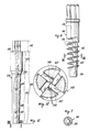
- the screw 10 consists of two distinct basic parts, namely a cylindrical upper neck 12 and a threaded shank 14.
- the threaded shank 14 is coaxial to the neck 12 and integral with it, and connects to the neck 12 via a short frusto-conical connecting section 20. This latter can however be absent, the frusto-conical surface of the screw core then extending directly from the periphery of the base of the cylindrical neck 12.
- the upper portion of the cylindrical neck 12 is intended to project beyond the bone, whereas the rest of the neck 12 is surrounded by the cortical bone with the screw inserted.
- a cylindrical rather than frusto-conical shape has been chosen for the screw neck 12, so that when under load the neck does not transmit axial loads to the adjacent cortical bone, but is able to transmit to the cortical hone any loads perpendicular to the axis of the screw 10 via its lateral surface 13 which is surrounded by it when the screw has been applied.
- an axial prismatic cavity 16 (shown by dashed lines in Figure 1) to receive a suitable tool (Allen key or the like), not shown on the drawings, to enable the screw 10 to be manually screwed into the bone and to allow the screw to subsequently receive dental prostheses.
- a suitable tool (Allen key or the like), not shown on the drawings, to enable the screw 10 to be manually screwed into the bone and to allow the screw to subsequently receive dental prostheses.
- These latter can for example comprise a pin-stump for prosthetic application by the method of Dr. Vrespa (Cenacolo Gruppo Italiano Studi Implantari, Bologna, November 187; Atti Congresso Internazionale GISI, May 1988).
- a threaded or non-threaded axial hole 18 (shown dashed in Figure 1), for fixing to the screw a known healing plug (not shown) or whatever else may be required.
- the presence of the two cavities 16 and 18 allows a mesostructure to be applied by screwing or cementing depending on the choice made and the requirements of the particular case.
- the shank 14 comprises two coaxially aligned parts 22 and 24 forming a single piece and having two different types of thread.
- a first cylindrical single-start thread 26 of large pitch is provided on the upper part 22 of the shank 14.
- the first thread 26 is suitable for fixing into the spongy bone tissue, the relative thread having a trapezoidal cross-section with rounded edges.
- the helical crest of the turns of the first thread 26 lie on a cylindrical surface having a diameter equal to the diameter of the screw neck 12, the outer diameter of the first thread thus being constant throughout its entire length. Consequently the height of the thread increases from the top downwards.
- the frusto-conical connection 20 is not provided and if said surface is still cylindrical, the thread height starts from zero at its highest point.
- a second thread 28 with three starts, each with the same pitch as the first thread 26.
- the second thread 28 is self-tapping.
- the thread turns are of triangular cross-section with a rounded crest.
- the thread height is constant along the entire thread.
- the thread crests lie on a frusto-conical surface parallel to that of the core 32 of the second thread. Because it has three starts this latter acts from the fixing viewpoint substantially as a thread having a pitch equal to 1/3 of the effective pitch. This makes the thread suitable for fixing into the cortical bone, and in this specific case into the cortical bone opposite the point of introduction of the screw.
- the lengths of the various component parts of the screw are obviously such that when the screw is inserted into the bone the screw neck 12 lies mainly within the cortical bone on the side from which the screw is inserted, the intermediate part 22 of the shank 14 comprising the first thread 26 lies within the trabecular bone tissue, and the end part 24 of the shank 14 which contains the the second thread 28 lies mainly within the opposite cortical bone.
- the screw neck 12 and the second thread 28 may lie slightly within the trabecular bone tissue region as it is difficult to previously know the exact thickness of the cortical bone.
- both the core 34 of the upper part 22 of the shank 14 and the core 32 of the lower part 24 are frusto-conical (the relative lateral surfaces being parallel), but with a small step 36 between them.
- the first operation consists of drilling in the bone a precision hole 40 shaped as in Figure 2.
- the cutter 100 consists of a shank 102 of conventional shape, a spacer portion or extension 104, and a cutter portion 106.
- the shank 102 is connected into the already mentioned quick-connection mechanism of the drill.
- the purpose of the extension 104 which is of suitable length, is merely to enable the cutter portion 106 to reach the required point, for example when a hole is to be drilled between two teeth adjacent to a missing tooth. If this requirement does not arise then the extension 104 can be absent.
- the actual cutter part 106 consists substantially of three coaxial cutting bodies 103, 105 and 107, which are rigid with each other and arranged to produce three hole portions of circular cross-section and having a diameter which respectively decreases towards the interior of the bone.
- the cutter 100 terminates with a tip 109 of conventional type and comprises an axial channel 108 communicating with the apertures 110, 112 and 114 visible in Figure 9.
- the channel 108 enables the iosotonic cooling liquids to be discharged during bone drilling.
- a circular line 111 is engraved or otherwise reproduced on the cutting body 103 to visibly indicate the exact level to which the cutter 100 must penetrate into the bone. When the line 111 has reached the level of the bone surface it is therefore certain that the cutter has reached the required depth.
- the reamer 140 must necessarily be operated manually.
- the reamer 140 comprises a shank part 142 of hexagonal cross-section to be engaged by a suitable tool for the manual reaming of said stepped cavity, plus a reamer part 144, which has a relief angle suitable for cutting the bone tissue.
- the reamer part 144 is itself divided into two sections, namely a first section 143 for producing a cylindrical hole portion and a second section 145 for producing a frusto-conical hole portion.
- the first section 143 connects to the second section 145 via a frusto-conical connection 141.
- the reamer 140 also comprises an axial channel 146 which passes completely through it and communicates with lateral apertures 148 provided between the cutting edges.
- the lateral apertures 148 are four in number, two in the groove 147 and two in the opposite groove 149. The isotonic liquid is fed through the channel 146 to reduce bone necrosis.
- This hole is obtained of the type shown in Figure 2.
- This hole can also be a through hole or can stop at a certain distance D from the outer surface of the opposite cortical bone.
- the first portion 42 of the hole 40 is cylindrical and has a diameter less by a few microns than the diameter of the cylindrical neck 12 (Figure 1) of the screw.
- the height of this first portion 42 is equal to or slightly greater than the thickness of the cortical bone 50, and in any event sufficient for receiving that part of the neck 12 of the screw 10 which is intended to enter the bone.
- the hole 40 terminates with a third portion 48, which is nothing other than the prolongation into the opposite cortical bone 54 of the directrices of the second hole portion 46.
- the hole will also not have said connect ion port ion 44, the second frusto-conical portion of the hole then extending directly from the base perimeter of the first cylindrical portion 42 of the hole.
- the reamer 140 ( Figure 11) will also not have the frusto-conical connecting section 141.
- the third portion 48 of the hole 40 is slightly longer (for example by 1 mm) than the corresponding lower part 24 of the shank 14 of the screw 10 ( Figure 1). The purpose of this is to prevent destruction of the female thread in the bone by any over-tightening of the screw, which could occur if the two said lengths are equal. In this respect any further advancement of the screw is prevented by the base 41 of the hole 40.
- the slightly longer length of the hole 40 results in adhesion between the conical cavity and the core of the screw. This also compensates for tolerances.
- the upper cortical bone 50 becomes covered by the gingive 55 (see Figure 2), so that this latter has to be perforated by conventional tools before proceeding with the drilling.
- the hole will therefore also comprise an upper gingival portion 49.
- a female thread (not shown in the figures) is formed in the side wall of its second portion 46 to receive the first thread 26 of the shank 14 of the screw 10. This is obtained using the tapper 60 shown in Figure 3.
- the first part 22 of the shank 14 and the respective part of the neck 12 are normally coated with titanium in known manner by plasma spray treatment, which slightly increases its dimensions.
- the dimensions of the tapping thread 62 and of the core 64 of the part 68 of the tapper 60 must be proportionally increased with respect to the dimensions of the bare screw, as must the dimensions of the parts 46, 42 and 44 of the hole 40.
- the lower frusto-conical part 66 of the tapper 60 is unthreaded, it has the same length as the corresponding second part 24 of the shank 14 of the screw 10, and at most has the same transverse dimensions as the core 32 of said part 24 of the screw.
- the tapper also comprises an upper part 70 substantially analogous to the neck 12 of the screw 10, the part 70 upperly comprising a projection 72 having a polygonal cross-section for engagement by a suitable tool (not shown) to enable the tapper 60 to be inserted.
- This latter comprises a longitudinal groove 74 of substantially trapezoidal cross-section extending along the entire tapper (see also Figures 4 and 5), its purpose having already been stated. It will be noted that the edges 73 of the groove 74 are rounded, for the previously stated reasons.
- FIGs 6 and 7 show a modification of the tapper according to the invention which has proved particularly convenient.
- the tapper 160 is particularly suitable for tapping holes for receiving screws without the connection portion 20, so that the relative precision hole will be without the portion 44.
- the only true difference compared with the tapper 60 of Figures 3 to 5 is that instead of the longitudinal groove 74 ( Figure 3) for discharging the organic liquids there is a coaxial circular channel 174 which passes longitudinally through the entire tapper 160. This channel communicates with the outside not only at its two ends but also via the series of apertures 176 provided in the core part 164, each aperture opening between two successive turns of the tapping thread 162.
- Figure 8 shows a modification of the screw according to the invention which is particularly suitable for orthopedics, for example for fixing a plate to a femur.
- the screw 80 is shown in Figure 8 already inserted into the bone. It differs from the screw 10 of Figure 1 only by the presence of a third self-tapping thread 23 provided on the lateral surface of the screw neck 112.
- the third thread 23 can be provided only if a counteracting element 82 is present, such as a plate resting on the surface of the femur cortical bone 50.
- the plate 82 prevents lifting and destruction of the surface layer of the cortical bone 50 when the self-tapping thread 23 grips the cortical bone 50.
- the third thread 23 could also be not of self-tapping type.
- a relative female thread is formed by a suitable tapper (not shown).
- the relative hole portion corresponding to the neck 112 of the screw 80 is consequently given a slightly larger diameter than the relative core 132 of the thread 23 of the screw 80, but less than the outer diameter of the thread 23, for the same reasons as stated for the hole corresponding to the second thread 28.
- the orthopedics screw 80 results in optimum stable fixing to the bone.
Priority Applications (1)
| Application Number | Priority Date | Filing Date | Title |
|---|---|---|---|
| EP93102625A EP0554915B1 (fr) | 1989-10-26 | 1990-10-11 | Outil de filetage pour former un filet femelle dans une forure tronconique précise d'un os |
Applications Claiming Priority (2)
| Application Number | Priority Date | Filing Date | Title |
|---|---|---|---|
| IT2213989 | 1989-10-26 | ||
| IT02213989A IT1237496B (it) | 1989-10-26 | 1989-10-26 | Dispositivo a vite per l'ancoraggio di protesi alle ossa, metodo per l'applicazione di tale dispositivo e relativa attrezzatura |
Related Child Applications (2)
| Application Number | Title | Priority Date | Filing Date |
|---|---|---|---|
| EP93102625.6 Division-Into | 1993-02-19 | ||
| EP93102624.9 Division-Into | 1993-02-19 |
Publications (2)
| Publication Number | Publication Date |
|---|---|
| EP0424734A1 true EP0424734A1 (fr) | 1991-05-02 |
| EP0424734B1 EP0424734B1 (fr) | 1995-03-01 |
Family
ID=11192075
Family Applications (3)
| Application Number | Title | Priority Date | Filing Date |
|---|---|---|---|
| EP93102625A Expired - Lifetime EP0554915B1 (fr) | 1989-10-26 | 1990-10-11 | Outil de filetage pour former un filet femelle dans une forure tronconique précise d'un os |
| EP93102624A Withdrawn EP0557899A1 (fr) | 1989-10-26 | 1990-10-11 | Outil coupant pour former une forure tronconique précise dans un os |
| EP90119459A Expired - Lifetime EP0424734B1 (fr) | 1989-10-26 | 1990-10-11 | Dispositif à vis pour la fixation de prothèses aux os |
Family Applications Before (2)
| Application Number | Title | Priority Date | Filing Date |
|---|---|---|---|
| EP93102625A Expired - Lifetime EP0554915B1 (fr) | 1989-10-26 | 1990-10-11 | Outil de filetage pour former un filet femelle dans une forure tronconique précise d'un os |
| EP93102624A Withdrawn EP0557899A1 (fr) | 1989-10-26 | 1990-10-11 | Outil coupant pour former une forure tronconique précise dans un os |
Country Status (8)
| Country | Link |
|---|---|
| US (2) | US5259398A (fr) |
| EP (3) | EP0554915B1 (fr) |
| AT (2) | ATE119011T1 (fr) |
| CA (1) | CA2028597C (fr) |
| DE (2) | DE69017349T2 (fr) |
| DK (1) | DK0424734T3 (fr) |
| ES (1) | ES2070236T3 (fr) |
| IT (1) | IT1237496B (fr) |
Cited By (38)
| Publication number | Priority date | Publication date | Assignee | Title |
|---|---|---|---|---|
| WO1993000518A1 (fr) * | 1991-06-25 | 1993-01-07 | Synthes Ag, Chur | Element de fixation |
| WO1994004086A1 (fr) * | 1992-08-25 | 1994-03-03 | Alexandre Worcel | Dispositif d'osteosynthese |
| DE4332075A1 (de) * | 1992-09-25 | 1994-03-31 | Herbst Bremer Goldschlaegerei | Schraubimplantat und Vorrichtung zum Eindrehen desselben in eine Aufnahmebohrung eines Kiefers |
| EP0438048B1 (fr) * | 1990-01-15 | 1994-05-18 | Friatec Aktiengesellschaft Keramik- und Kunststoffwerke | Implant dentaire |
| EP0599794A2 (fr) * | 1992-11-26 | 1994-06-01 | Medevelop Ab | Elément de fixation pour tissu osseux |
| WO1994017750A1 (fr) * | 1992-11-26 | 1994-08-18 | Medevelop Ab | Element d'ancrage dans des tissus osseux |
| WO1994021184A1 (fr) * | 1993-03-25 | 1994-09-29 | Dietmar Pennig | Tige de fixation pour osteosynthese |
| WO1995004504A1 (fr) * | 1993-08-05 | 1995-02-16 | Hi-Shear Fasteners Europe Limited | Ambocepteur externe |
| US5433719A (en) * | 1993-03-25 | 1995-07-18 | Pennig; Dietmar | Fixation pin for small-bone fragments |
| EP0705572A2 (fr) * | 1994-10-03 | 1996-04-10 | Synthes AG, Chur | Plaque de fixation et vis à os |
| US5564926A (en) * | 1992-11-26 | 1996-10-15 | Medevelop Ab | Anchoring element for anchorage in bone tissue |
| US5609595A (en) * | 1993-03-25 | 1997-03-11 | Pennig; Dietmar | Fixation pin for small-bone fragments |
| WO1997025933A1 (fr) * | 1996-01-18 | 1997-07-24 | Implant Innovations, Inc. | Implant dentaire visse a frottement reduit |
| EP0819410A1 (fr) * | 1996-07-19 | 1998-01-21 | Lucia Biemmi | Implant dentaire et fraise y associée |
| WO2000003649A1 (fr) * | 1998-07-13 | 2000-01-27 | Sepitec Foundation | Vis d'osteosynthese, s'utilisant notamment lors d'une fixation par vis vertebrale translaminaire |
| WO2000003657A1 (fr) * | 1998-07-17 | 2000-01-27 | Astrazeneca Ab | Implant |
| EP1033111A1 (fr) * | 1999-03-01 | 2000-09-06 | Sulzer Orthopedics Ltd. | Vis à os pour l'ancrage d'un clou médullaire |
| WO2000054696A1 (fr) * | 1999-03-16 | 2000-09-21 | Antonio Gallicchio | Implant pour dents artificielles |
| WO2001039690A1 (fr) * | 1999-12-03 | 2001-06-07 | Imz Fertigungs- Und Vertriebsgesellschaft Für Dentale Technologie Mbh | Implant dentaire individuel intra-osseux |
| WO2001039689A1 (fr) * | 1999-12-03 | 2001-06-07 | Imz Fertigungs- Und Vertriebsgesellschaft Für Dentale Technologie Mbh | Implant prothetique intra-osseux dote d'une section de centrage |
| EP1120096A1 (fr) * | 1992-02-28 | 2001-08-01 | AstraZeneca AB | Dispositif de fixation pour une prothèse de l'articulation de la hanche |
| US6355043B1 (en) | 1999-03-01 | 2002-03-12 | Sulzer Orthopedics Ltd. | Bone screw for anchoring a marrow nail |
| EP1374796A1 (fr) | 2002-06-19 | 2004-01-02 | Sweden & Martina S.p.a. | Implant dentaire |
| EP1402843A1 (fr) * | 2002-09-26 | 2004-03-31 | GC Corporation | Jeu de foret pour implant dentaire autotaraudeur |
| WO2004041111A1 (fr) * | 2002-11-05 | 2004-05-21 | Gebr. Brasseler Gmbh & Co. Kg | Implant dentaire |
| WO2004058095A1 (fr) * | 2002-12-30 | 2004-07-15 | Nobel Biocare Ab (Publ) | Foret |
| WO2006049385A1 (fr) * | 2004-11-03 | 2006-05-11 | Kwang Hoon Lee | Fixation pour implant dentaire |
| EP1723917A1 (fr) * | 2005-05-20 | 2006-11-22 | DePuy Products, Inc. | Appareil pour l'implantation d'un élément de fixation osseuse |
| WO2007086622A1 (fr) * | 2006-01-27 | 2007-08-02 | Osstem Implant Co., Ltd | Dispositif de fixation |
| EP2131782A2 (fr) * | 2007-03-31 | 2009-12-16 | 3M IMTEC Corporation | Modele de filetage d'implant |
| CN101502432B (zh) * | 2008-02-04 | 2011-03-16 | 镱钛科技股份有限公司 | 回馈式安全钻头 |
| CN1984618B (zh) * | 2004-06-04 | 2011-06-01 | 斯特凡·诺伊迈尔 | 牙种植体 |
| US8029285B2 (en) | 2001-08-15 | 2011-10-04 | Astra Tech Ab | Implant, arrangement comprising an implant, and method for inserting said implant in bone tissue |
| CN102988106A (zh) * | 2012-12-29 | 2013-03-27 | 江苏百得医疗器械有限公司 | 骨科运动学锁定接骨螺钉 |
| EP2571435A1 (fr) * | 2010-05-19 | 2013-03-27 | DePuy Spine, Inc. | Ancrages osseux |
| USRE44800E1 (en) | 1998-07-17 | 2014-03-11 | Astrazeneca Ab | Dental implant |
| EP1030622B2 (fr) † | 1997-11-11 | 2014-05-14 | Nobel Biocare Services AG | Implant filete permettant d'obtenir un ancrage sur dans un os |
| CN103989512A (zh) * | 2013-03-01 | 2014-08-20 | 中山大学 | 便携式骨折外固定器 |
Families Citing this family (292)
| Publication number | Priority date | Publication date | Assignee | Title |
|---|---|---|---|---|
| US5836731A (en) * | 1987-05-20 | 1998-11-17 | Mathread, Inc. | Anti-cross threading fastener |
| USRE37646E1 (en) * | 1989-11-14 | 2002-04-09 | Sulzer Dental Inc. | Dental implant system |
| WO1991018559A1 (fr) * | 1990-06-06 | 1991-12-12 | Ronald Sekel | Prothese de la hanche |
| US5344458A (en) * | 1992-08-06 | 1994-09-06 | Bonutti Peter M | Arthroplasty component |
| SE9202911D0 (sv) * | 1992-10-05 | 1992-10-05 | Astra Ab | Fixture provided with micro-threads |
| US8070786B2 (en) | 1993-01-21 | 2011-12-06 | Acumed Llc | System for fusing joints |
| US5964768A (en) * | 1993-01-21 | 1999-10-12 | Acumed, Inc. | Tapered bone screw with continuously varying pitch |
| US6299615B1 (en) | 1993-01-21 | 2001-10-09 | Acumed, Inc. | System for fusing joints |
| US6030162A (en) * | 1998-12-18 | 2000-02-29 | Acumed, Inc. | Axial tension screw |
| US9161793B2 (en) | 1993-01-21 | 2015-10-20 | Acumed Llc | Axial tension screw |
| US6984235B2 (en) * | 1993-01-21 | 2006-01-10 | Acumed Llc | System for fusing joints |
| US6406296B1 (en) * | 1993-12-27 | 2002-06-18 | Bio-Lok International, Inc. | Implant with enlarged proximal segment |
| FR2718343B1 (fr) * | 1994-04-08 | 1996-12-20 | Francis Poulmaire | Matériel pour la préparation de la loge osseuse d'un implant-lame, support de prothèse dentaire. |
| USD385352S (en) * | 1994-05-02 | 1997-10-21 | Zimmer, Inc. | Suture anchor screw |
| US5520688A (en) * | 1994-07-20 | 1996-05-28 | Lin; Chih-I | Vertebral auxiliary fixation device |
| US5569252A (en) * | 1994-09-27 | 1996-10-29 | Justin; Daniel F. | Device for repairing a meniscal tear in a knee and method |
| US5730744A (en) * | 1994-09-27 | 1998-03-24 | Justin; Daniel F. | Soft tissue screw, delivery device, and method |
| US5536127A (en) * | 1994-10-13 | 1996-07-16 | Pennig; Dietmar | Headed screw construction for use in fixing the position of an intramedullary nail |
| DE19528242A1 (de) * | 1995-08-01 | 1997-02-06 | Roland Dr Dr Streckbein | Werkzeug zum Präparieren von Hohlräumen in Knochen |
| WO1996018354A2 (fr) * | 1994-12-16 | 1996-06-20 | Roland Streckbein | Instrument permettant de former des cavites dans des os |
| JP3375771B2 (ja) * | 1995-02-02 | 2003-02-10 | マニー株式会社 | ピーソーリーマ又はゲーツドリル |
| US5605457A (en) * | 1995-02-13 | 1997-02-25 | Crystal Medical Technology, A Division Of Folsom Metal Products, Inc. | Implant connector |
| US5605458A (en) * | 1995-03-06 | 1997-02-25 | Crystal Medical Technology, A Division Of Folsom Metal Products, Inc. | Negative load flank implant connector |
| US5730155A (en) * | 1995-03-27 | 1998-03-24 | Allen; Dillis V. | Ethmoidal implant and eyeglass assembly and its method of location in situ |
| FR2734707B1 (fr) * | 1995-05-30 | 1997-08-29 | Guedj Leon | Equipement chirurgical d'implantologie dentaire et elements, implant dentaire et instruments de forage, constitutifs |
| US5730566A (en) * | 1995-07-21 | 1998-03-24 | Goodwin; Jerry J. | Anti-cross threading fastener |
| JPH11509915A (ja) * | 1995-07-21 | 1999-08-31 | ガーバー、マイケル、エイ. | クロスネジ防止ネジ締結装置 |
| DE59509247D1 (de) * | 1995-09-06 | 2001-06-13 | Synthes Ag | Knochenplatte |
| DE19536716A1 (de) * | 1995-09-30 | 1997-04-03 | Lauks Nikola | Bohrer zur Herstellung von Knochenkavitäten für zahnärztliche Implantate |
| US6152963A (en) * | 1996-01-04 | 2000-11-28 | Joint Medical Products Corporation | Method and apparatus for fitting a prosthesis to a bone |
| EP0870118B1 (fr) * | 1996-01-18 | 1999-06-30 | Werner Flückiger | Vis d'ecartement |
| US6117162A (en) * | 1996-08-05 | 2000-09-12 | Arthrex, Inc. | Corkscrew suture anchor |
| FR2753368B1 (fr) * | 1996-09-13 | 1999-01-08 | Chauvin Jean Luc | Cage d'osteosynthese expansive |
| EP0832619B1 (fr) * | 1996-09-30 | 2004-12-22 | Brainbase Corporation | Implant avec des particules bioactifs et procédé de production |
| ES2127116B1 (es) * | 1996-10-24 | 1999-11-16 | Dalmau Marcela Ridao | Nuevos expansores atraumaticos del hueso para fijaciones protesicas dentales. |
| AU1188297A (en) * | 1997-01-14 | 1998-08-07 | Synthes Ag, Chur | Pedicle screw with double thread |
| EP0944371A1 (fr) * | 1997-02-04 | 1999-09-29 | Alain Fouere | Tampon meatique vissable pour canal lacrymal |
| US5795160A (en) * | 1997-02-06 | 1998-08-18 | Hahn; Jack A. | Tapered dental implant in a stepped orifice |
| DE69838856T2 (de) | 1997-02-11 | 2008-12-11 | Warsaw Orthopedic, Inc., Warsaw | Platte für die vordere Halswirbelsäule mit Fixierungssystem für eine Schraube |
| JP4467647B2 (ja) | 1997-02-11 | 2010-05-26 | ウォーソー・オーソペディック・インコーポレーテッド | 骨プレーティングシステム |
| CA2444232C (fr) * | 1997-02-11 | 2006-04-11 | Gary Karlin Michelson | Systeme de fixation anterieure de la colonne vertebrale au moyen d'une plaque et broche osseuse |
| US5954504A (en) * | 1997-03-31 | 1999-09-21 | Biohorizons Implants Systems | Design process for skeletal implants to optimize cellular response |
| US5980524A (en) | 1997-06-02 | 1999-11-09 | Innovasive Devices, Inc. | Device for repairing a meniscal tear in a knee and method |
| IT1295028B1 (it) * | 1997-09-18 | 1999-04-27 | Walter Veneziano | Assieme di una fresa alesatrice e di una protesi per implantologia ossea a perno avvitato |
| EP0941705A3 (fr) | 1998-03-10 | 2000-02-02 | Howmedica Inc. | Vis et méthode pour fixation sur un substrat du type osseux |
| US6296641B2 (en) * | 1998-04-03 | 2001-10-02 | Bionx Implants Oy | Anatomical fixation implant |
| ATE299672T1 (de) | 1998-11-26 | 2005-08-15 | Synthes Ag | Schraube |
| US6273721B1 (en) * | 1998-12-07 | 2001-08-14 | Maurice Valen | Dental implant |
| US9521999B2 (en) | 2005-09-13 | 2016-12-20 | Arthrex, Inc. | Fully-threaded bioabsorbable suture anchor |
| US8343186B2 (en) | 2004-04-06 | 2013-01-01 | Arthrex, Inc. | Fully threaded suture anchor with transverse anchor pin |
| US8821541B2 (en) | 1999-02-02 | 2014-09-02 | Arthrex, Inc. | Suture anchor with insert-molded rigid member |
| US6210376B1 (en) | 1999-04-08 | 2001-04-03 | New York University | Cannulated delivery pin |
| US6423067B1 (en) * | 1999-04-29 | 2002-07-23 | Theken Surgical Llc | Nonlinear lag screw with captive driving device |
| US6096060A (en) * | 1999-05-20 | 2000-08-01 | Linvatec Corporation | Bioabsorbable threaded soft tissue anchor system |
| US6655962B1 (en) * | 1999-08-17 | 2003-12-02 | Nobel Biocare Usa, Inc. | Immediate provisional implant |
| DE29916459U1 (de) * | 1999-09-18 | 1999-12-30 | Busch & Co Gmbh & Co | Gekühltes rotierendes dental-chirurgisches Instrument |
| AU755551B2 (en) * | 1999-10-06 | 2002-12-12 | Astra-Tech Aktiebolag | Femur fixture and set of femur fixtures |
| US6540752B1 (en) * | 1999-11-01 | 2003-04-01 | Greg Hicken | Threaded bone tunnel dilator |
| WO2001049200A2 (fr) * | 2000-01-04 | 2001-07-12 | Biolok International, Inc. | Implant a segment proximal elargi |
| KR200188511Y1 (ko) * | 2000-01-06 | 2000-07-15 | 구자교 | 척추용 보철 플러그 |
| US7635390B1 (en) | 2000-01-14 | 2009-12-22 | Marctec, Llc | Joint replacement component having a modular articulating surface |
| US6565566B1 (en) * | 2000-03-22 | 2003-05-20 | Spinal Concepts, Inc. | Sacral screw assembly and method |
| SE516282C2 (sv) * | 2000-04-04 | 2001-12-10 | Nobel Biocare Ab | Implantat försett med anslutnings- och hålisättningsdelar samt förfarande vid dylikt implantat |
| US6468277B1 (en) * | 2000-04-04 | 2002-10-22 | Ethicon, Inc. | Orthopedic screw and method |
| US6568044B1 (en) | 2000-04-10 | 2003-05-27 | Susan F. Kidd | Attachment device for pliant material |
| SE523765C2 (sv) * | 2000-07-12 | 2004-05-18 | Entific Medical Systems Ab | Skruvformat förankringselement för permanent förankring av benförankrade hörapparater och öron- eller ögonproteser i skallbenet |
| FR2814058B1 (fr) * | 2000-09-19 | 2005-10-28 | Guy Gabriel Peltier | Jeu d'implants et implants correspondants |
| US6561741B2 (en) | 2000-12-19 | 2003-05-13 | Michael A. Garver | Fastener with aligning lead thread |
| US6306140B1 (en) * | 2001-01-17 | 2001-10-23 | Synthes (Usa) | Bone screw |
| DE10114627A1 (de) * | 2001-03-23 | 2002-10-02 | Herbert Hatzlhoffer | Implantat |
| US6565573B1 (en) | 2001-04-16 | 2003-05-20 | Smith & Nephew, Inc. | Orthopedic screw and method of use |
| US7235079B2 (en) | 2004-11-18 | 2007-06-26 | Acumed Llc | Composite bone fasteners |
| US6770075B2 (en) | 2001-05-17 | 2004-08-03 | Robert S. Howland | Spinal fixation apparatus with enhanced axial support and methods for use |
| ES2263617T3 (es) | 2001-05-28 | 2006-12-16 | Synthes Ag Chur | Placa de osteosintesis para la fijacion de fracturas proximales del humero. |
| AUPR597701A0 (en) * | 2001-06-28 | 2001-07-19 | Portland Orthopaedics Pty Limited | Joint prosthesis |
| US6887077B2 (en) * | 2001-08-17 | 2005-05-03 | Implant Innovations, Inc. | Immediate load dental implant system and method of use |
| US6890335B2 (en) * | 2001-08-24 | 2005-05-10 | Zimmer Spine, Inc. | Bone fixation device |
| US7708741B1 (en) | 2001-08-28 | 2010-05-04 | Marctec, Llc | Method of preparing bones for knee replacement surgery |
| DE20115184U1 (de) | 2001-09-14 | 2001-11-15 | Busch & Co Kg | Rotierendes dental-chirurgisches Instrument mit Kühlmittelkanal |
| US6953463B2 (en) * | 2001-10-12 | 2005-10-11 | Hs West Investments, Llc | Interference screws having increased proximal diameter |
| CN1271977C (zh) * | 2001-12-04 | 2006-08-30 | 库尔斯恩蒂斯股份公司 | 骨螺钉以及用于骨断片的复位、加压和固定的装置 |
| US8216243B2 (en) | 2001-12-04 | 2012-07-10 | Synthes Usa, Llc | Headless compression screw with integrated reduction-compression instrument |
| US6875215B2 (en) | 2002-02-15 | 2005-04-05 | John Stanley Taras | Distraction pin for fracture fixation |
| US7005974B2 (en) * | 2002-04-19 | 2006-02-28 | Donnelly Corporation | Vehicle imaging system |
| US20050101961A1 (en) * | 2003-11-12 | 2005-05-12 | Huebner Randall J. | Bone screws |
| EP1524948B2 (fr) * | 2002-07-26 | 2018-05-02 | Bredent Dentalgeräte und Materialien Fach- und Organisationsberatung Peter Brehm | Implant dentaire a tete d'ancrage et corps a visser |
| US7517350B2 (en) * | 2002-11-20 | 2009-04-14 | Orthopediatrics Corp. | Convertible threaded compression device and method of use |
| US7641677B2 (en) * | 2002-11-20 | 2010-01-05 | Orthopediatrics Corp. | Compression bone fragment wire |
| US7235078B2 (en) * | 2002-11-26 | 2007-06-26 | Hs West Investments Llc | Protective devices for use with angled interference screws |
| JP4575784B2 (ja) * | 2003-03-28 | 2010-11-04 | ジンテーズ ゲゼルシャフト ミト ベシュレンクテル ハフツング | 止めネジ |
| IL156033A0 (en) | 2003-05-21 | 2004-03-28 | Ophir Fromovich Ophir Fromovic | Dental implant |
| DE20308993U1 (de) * | 2003-06-06 | 2003-08-28 | Gummi Jaeger Gmbh | Vorrichtung zum Handhaben von Kegeln für das Kegel- oder Bowlingspiel, insb. bei der Reinigung |
| US7241144B2 (en) * | 2003-07-30 | 2007-07-10 | Bio-Lok International, Inc. | Method of bone expansion and compression for receiving a dental implant using threaded expanders |
| US7708766B2 (en) * | 2003-08-11 | 2010-05-04 | Depuy Spine, Inc. | Distraction screw |
| US8105367B2 (en) | 2003-09-29 | 2012-01-31 | Smith & Nephew, Inc. | Bone plate and bone plate assemblies including polyaxial fasteners |
| DE10356920B4 (de) * | 2003-10-30 | 2007-02-22 | Rainer Lippe | In einen menschlichen Kiefer endostal einschraubbares Dentalimplantat zur Aufnahme und Fixierung eines Zahnersatzes |
| US7699852B2 (en) * | 2003-11-19 | 2010-04-20 | Zimmer Spine, Inc. | Fenestrated bone tap and method |
| WO2005058175A1 (fr) | 2003-12-19 | 2005-06-30 | Depuy International Limited | Vis pour os |
| US7044702B2 (en) * | 2004-01-22 | 2006-05-16 | Jen-Tong Ho | Screw with a plurality of screwing angles and mold device for forming the same |
| US7845945B2 (en) * | 2004-01-28 | 2010-12-07 | Stanton R. Canter | Anchoring element for use in bone |
| SE0400546D0 (sv) * | 2004-03-05 | 2004-03-05 | Dan Lundgren | Rörformigt benförankringselement |
| WO2005112816A1 (fr) * | 2004-04-21 | 2005-12-01 | Gebr. Brasseler Gmbh & Co. Kg | Implant dentaire |
| US7758612B2 (en) * | 2004-04-27 | 2010-07-20 | Tyco Healthcare Group Lp | Surgery delivery device and mesh anchor |
| US8114099B2 (en) | 2004-04-27 | 2012-02-14 | Tyco Healthcare Group Lp | Absorbable anchor for hernia mesh fixation |
| US10478179B2 (en) * | 2004-04-27 | 2019-11-19 | Covidien Lp | Absorbable fastener for hernia mesh fixation |
| WO2005117742A1 (fr) * | 2004-06-04 | 2005-12-15 | Stefan Neumeyer | Implant dentaire |
| WO2006007553A2 (fr) * | 2004-07-01 | 2006-01-19 | Smith & Nephew, Inc. | Elements de fixation |
| US8114158B2 (en) | 2004-08-03 | 2012-02-14 | Kspine, Inc. | Facet device and method |
| US7799062B2 (en) * | 2004-11-30 | 2010-09-21 | Stryker Trauma S.A. | Self-guiding threaded fastener |
| US7736380B2 (en) | 2004-12-21 | 2010-06-15 | Rhausler, Inc. | Cervical plate system |
| US8540777B2 (en) * | 2005-01-31 | 2013-09-24 | Arthrex, Inc. | Method and apparatus for performing an open wedge, high tibial osteotomy |
| US8771279B2 (en) | 2005-01-31 | 2014-07-08 | Arthrex, Inc. | Method and apparatus for performing an osteotomy in bone |
| US7677891B2 (en) * | 2005-02-01 | 2010-03-16 | Implant Direct Int'l, Inc. | Tapered endosseous dental implants with external multiple lead threads |
| FR2885029B1 (fr) * | 2005-04-29 | 2007-06-15 | Gerard Scortecci | Dispositif pour l'implantologie dentaire |
| AU2006272646C1 (en) | 2005-07-25 | 2018-06-21 | Smith & Nephew, Inc. | Systems and methods for using polyaxial plates |
| US8382807B2 (en) | 2005-07-25 | 2013-02-26 | Smith & Nephew, Inc. | Systems and methods for using polyaxial plates |
| US20070053765A1 (en) * | 2005-07-29 | 2007-03-08 | Warnick David R | Thread on a bone screw |
| DE102005038038A1 (de) * | 2005-08-09 | 2007-02-15 | Streckbein, Roland, Dr.Dr. | Werkzeuge zum Herstellen und Vorbereiten einer Bohrung zur Aufnahme von Zahnimplantaten und entsprechendes Zahnimplantat |
| GB0516911D0 (en) * | 2005-08-18 | 2005-09-28 | Biocomposites Ltd | Tensegrity osteotomy system |
| US20070233145A1 (en) * | 2005-08-18 | 2007-10-04 | Biocomposites Ltd. | Tensegrity osteotomy system |
| US7559846B2 (en) | 2005-10-28 | 2009-07-14 | Sandvik Medical Solutions Oregon, Inc. | Machining method and apparatus for thread formation on workpiece |
| DE102005056119A1 (de) * | 2005-11-27 | 2007-05-24 | Zipprich, Holger, Dipl.-Ing. | Temporäre Schraube für kieferorthopädische Anwendung mit gesteigerter Festigkeit im Knochen |
| US7255523B2 (en) * | 2005-12-22 | 2007-08-14 | Prime Source Building Products, Inc. | Dual threaded screw for composite materials |
| US8740947B2 (en) * | 2006-02-15 | 2014-06-03 | Warsaw, Orthopedic, Inc. | Multiple lead bone fixation apparatus |
| US8075604B2 (en) * | 2006-02-16 | 2011-12-13 | Warsaw Orthopedic, Inc. | Multi-thread bone screw and method |
| ES2324436B1 (es) * | 2006-03-10 | 2010-05-25 | Bti, I+D S.L. | Expansor- compactador de cresta osea, y herramientas asociadas. |
| US8147531B2 (en) * | 2006-03-17 | 2012-04-03 | Tornier, Inc. | Compression pin with opposed threaded regions |
| ITMI20060653A1 (it) * | 2006-04-04 | 2007-10-05 | I D I Evolution S R L | Sistema di identificazione della tipologia ossea |
| US7950888B2 (en) * | 2006-04-13 | 2011-05-31 | Japan Power Fastening Co., Ltd. | Self-penetrating screw |
| US20080051793A1 (en) * | 2006-08-04 | 2008-02-28 | David Erickson | Drill-tap tool |
| ITTO20060599A1 (it) * | 2006-08-11 | 2008-02-12 | Itw Construction Products Ital | Organo di ancoraggio di strutture in legno o metallo ad una parete |
| DE102006057019B4 (de) * | 2006-08-21 | 2008-07-31 | Teichmann, Gernot, Dr. Dr. | Vorrichtung zur Herstellung einer schneckenförmigen Ausnehmung im Kieferknochen |
| US7806686B2 (en) * | 2006-08-24 | 2010-10-05 | Toads Llc | Anchor apparatus and method for orthodontic appliances |
| US20080085488A1 (en) * | 2006-08-29 | 2008-04-10 | Sargon Lazarof | Universal one-step drill |
| US20080177330A1 (en) * | 2006-10-24 | 2008-07-24 | Ralph James D | Self-locking screws for medical implants |
| US8114128B2 (en) * | 2006-11-01 | 2012-02-14 | Depuy Mitek, Inc. | Cannulated suture anchor |
| ES2299386B1 (es) * | 2006-11-08 | 2009-04-01 | Jose Duran Von Arx | Microimplante adaptable, aplicable a sistemas de anclaje esqueletico. |
| US20080112775A1 (en) * | 2006-11-12 | 2008-05-15 | Tai-Ping Hsu | Superdrilling Tri-shaft Screw |
| US20100112517A1 (en) * | 2008-11-06 | 2010-05-06 | Chen Chu-Leon | Drill for rapid dental implant |
| WO2008064665A1 (fr) | 2006-12-02 | 2008-06-05 | Gernot Teichmann | Dispositif de production d'un évidement hélicoïdal dans l'os de la mâchoire |
| US20080187886A1 (en) * | 2007-02-07 | 2008-08-07 | Robb T Tait | Dental implant with constant thread crest width |
| DE102008006093B4 (de) * | 2007-02-14 | 2017-02-02 | Bernhard Förster Gmbh | Schraubimplantat für die Orthodontie |
| US7909883B2 (en) * | 2007-02-21 | 2011-03-22 | Sidebotham Christopher G | Percutaneous implant for limb salvage |
| US8128671B2 (en) * | 2007-04-04 | 2012-03-06 | Warsaw Orthopedic, Inc. | Variable flank bone screw |
| US20140142636A1 (en) * | 2007-04-16 | 2014-05-22 | Robert Hes | Bone Screw |
| EP1982672A1 (fr) * | 2007-04-18 | 2008-10-22 | Micerium SPA | Dispositif d'implant dentaire |
| FR2916624B1 (fr) * | 2007-05-29 | 2009-08-21 | Small Bone Innovations Interna | Vis a os, notamment d'osteosynthese |
| EP2155086B1 (fr) | 2007-06-06 | 2016-05-04 | K2M, Inc. | Dispositif médical de correction d'une difformité |
| DE102007035183B4 (de) * | 2007-07-27 | 2010-05-12 | Ludwig Hettich & Co. | Erzeugung einer planmäßigen Eigenspannungsverteilung in Bauteilen durch Einbringen von Schrauben oder Gewindestangen mit sich in Längsrichtung variabel verändernder Gewindesteigung |
| US8702754B2 (en) | 2007-09-14 | 2014-04-22 | Depuy Mitek, Llc | Methods for anchoring suture to bone |
| US8882801B2 (en) * | 2007-09-14 | 2014-11-11 | Depuy Mitek, Llc | Dual thread cannulated suture anchor |
| US8419332B2 (en) * | 2007-10-19 | 2013-04-16 | Atlas Bolt & Screw Company Llc | Non-dimpling fastener |
| US9277909B2 (en) | 2007-10-27 | 2016-03-08 | Parcus Medical, Llc | Suture anchor |
| WO2014189605A1 (fr) | 2013-03-15 | 2014-11-27 | Mark Brunsvold | Ancrage de suture |
| US7967848B2 (en) * | 2008-01-16 | 2011-06-28 | Custom Spine, Inc. | Spring-loaded dynamic pedicle screw assembly |
| GB2460909B (en) * | 2008-01-28 | 2010-09-08 | Mark B Sommers | Bone Nail |
| US20090280452A1 (en) * | 2008-05-09 | 2009-11-12 | Garfinkel Leonard M | Sinus bur having an edge without sharp points |
| US20090287246A1 (en) * | 2008-05-14 | 2009-11-19 | Depuy Mitek, Inc. | Knotless interface for threaded anchor |
| US9044282B2 (en) * | 2008-06-24 | 2015-06-02 | Extremity Medical Llc | Intraosseous intramedullary fixation assembly and method of use |
| TWM360687U (en) * | 2008-07-10 | 2009-07-11 | nai-chang Yu | Orthodontic temporary anchorage device |
| US8758012B2 (en) * | 2008-07-14 | 2014-06-24 | Nobel Biocare Services Ag | Compact dental implant |
| US9289202B2 (en) * | 2008-08-06 | 2016-03-22 | Syntorr, Inc. | Suture-retaining device and anchor |
| JP5562963B2 (ja) | 2008-09-10 | 2014-07-30 | ノベル バイオケア サーヴィシィズ アーゲー | 歯科インプラントを埋入するための装置および手順 |
| US20100094352A1 (en) * | 2008-10-10 | 2010-04-15 | Andrew Iott | Bone screw |
| US20140012322A1 (en) * | 2008-10-10 | 2014-01-09 | Brian Gayvey | Bone Screw |
| US20100121355A1 (en) | 2008-10-24 | 2010-05-13 | The Foundry, Llc | Methods and devices for suture anchor delivery |
| CA2742077A1 (fr) | 2008-10-30 | 2010-05-06 | Depuy Spine, Inc. | Systemes et procedes d'apport de ciment osseux a une ancre osseuse |
| US20100114315A1 (en) * | 2008-10-31 | 2010-05-06 | Manderson Easton L | Intramedullary locked compression screw for stabilization and union of complex ankle and subtalar deformities |
| US8828058B2 (en) | 2008-11-11 | 2014-09-09 | Kspine, Inc. | Growth directed vertebral fixation system with distractible connector(s) and apical control |
| FR2941507A1 (fr) * | 2009-01-29 | 2010-07-30 | Lisi Aerospace | Filetage a distribution de contraintes |
| ITTO20090022U1 (it) * | 2009-02-17 | 2010-08-18 | Savio Spa | Sistema di fissaggio di accessori su telai in materiale metallico per porte, finestre e simili |
| US8357183B2 (en) | 2009-03-26 | 2013-01-22 | Kspine, Inc. | Semi-constrained anchoring system |
| EP2429411B1 (fr) | 2009-05-12 | 2017-03-08 | The Foundry, LLC | Dispositifs de traitement d'un tissu musculo-squelettique malade ou lésé |
| WO2010132309A1 (fr) | 2009-05-12 | 2010-11-18 | Foundry Newco Xi, Inc. | Ancrage de suture sans point et procédés d'utilisation |
| US8282676B2 (en) * | 2009-05-28 | 2012-10-09 | Griffin T Hall | Tapered thread root transition on cortical bone fastener |
| US8652183B1 (en) | 2009-07-07 | 2014-02-18 | Mari S Truman | Multi-angle orthopedic expansion head fastener |
| US9095444B2 (en) | 2009-07-24 | 2015-08-04 | Warsaw Orthopedic, Inc. | Implant with an interference fit fastener |
| ES2710179T3 (es) * | 2009-09-07 | 2019-04-23 | Nobel Biocare Services Ag | Conjunto de implantación |
| ES2596828T3 (es) * | 2009-09-07 | 2017-01-12 | Nobel Biocare Services Ag | Componentes para el roscado guiado de un hueso |
| US9168071B2 (en) | 2009-09-15 | 2015-10-27 | K2M, Inc. | Growth modulation system |
| US8496692B2 (en) | 2009-09-21 | 2013-07-30 | Jmea Corporation | Locking securing member |
| US9419372B2 (en) * | 2009-10-27 | 2016-08-16 | Cardiac Pacemakers, Inc. | Vented set screw for implantable medical device |
| US8409261B2 (en) * | 2009-11-20 | 2013-04-02 | T. Hall Griffin | Engaging predetermined radial preloads in securing an orthopedic fastener |
| US8771325B2 (en) * | 2009-11-20 | 2014-07-08 | T. Hall Griffin | Tapered threaded orthopedic fastener engaging predetermined radial preloads |
| US8414629B2 (en) * | 2009-11-20 | 2013-04-09 | T. Hall Griffin | Limiting radial preloads in securing an orthopedic fastener |
| US8419779B2 (en) * | 2009-12-08 | 2013-04-16 | James A. Rinner | Systematic displacement bone screw |
| US8429374B2 (en) * | 2010-01-28 | 2013-04-23 | Sony Corporation | System and method for read-while-write with NAND memory device |
| EP2353540A1 (fr) * | 2010-01-28 | 2011-08-10 | Sudimplant | Ensemble d'un implant dentaire et d'un élément prothétique |
| US8992587B2 (en) | 2010-07-20 | 2015-03-31 | X-Spine Systems, Inc. | Spinal facet compression screw with variable pitch thread zones and buttress head |
| US8945193B2 (en) | 2010-07-20 | 2015-02-03 | X-Spine Systems, Inc. | Minimally invasive spinal facet compression screw and system for bone joint fusion and fixation |
| ITMI20102281A1 (it) * | 2010-12-14 | 2012-06-15 | Gabriele Caruso | Impianto dentale |
| US20120178048A1 (en) * | 2011-01-11 | 2012-07-12 | Cottrell Richard D | Dental implant with multiple thread patterns |
| US9662221B2 (en) * | 2011-01-26 | 2017-05-30 | Nextremity Solutions, Inc. | Upper extremity fusion devices and methods |
| US8709092B2 (en) | 2011-02-16 | 2014-04-29 | Genesis Medical Devices, LLC | Periprosthetic fracture management enhancements |
| DE202011100537U1 (de) * | 2011-02-16 | 2011-07-15 | Hager & Meisinger Gmbh | Knochenschraube |
| US8998612B2 (en) * | 2011-03-10 | 2015-04-07 | Megagen Implant Co, Ltd. | Dental implant fixture and implant system having the same |
| US8790375B2 (en) * | 2011-03-18 | 2014-07-29 | Raed M. Ali, M.D., Inc. | Transpedicular access to intervertebral spaces and related spinal fusion systems and methods |
| US9265620B2 (en) * | 2011-03-18 | 2016-02-23 | Raed M. Ali, M.D., Inc. | Devices and methods for transpedicular stabilization of the spine |
| KR101192662B1 (ko) * | 2011-03-22 | 2012-10-19 | 주식회사 이노바이오써지 | 임플란트 시술용 드릴 |
| US9644668B2 (en) * | 2011-03-28 | 2017-05-09 | Wamlez Pty Ltd. | Fastener |
| US9333009B2 (en) | 2011-06-03 | 2016-05-10 | K2M, Inc. | Spinal correction system actuators |
| WO2012174385A2 (fr) | 2011-06-15 | 2012-12-20 | Smith & Nephew, Inc. | Implant de verrouillage à angle variable |
| JP5156113B2 (ja) * | 2011-08-02 | 2013-03-06 | 株式会社松風 | 歯科用インプラント |
| US9636230B2 (en) * | 2011-08-25 | 2017-05-02 | Vikram Talwar | Interbody fusion implant and screw guide |
| US9155580B2 (en) | 2011-08-25 | 2015-10-13 | Medos International Sarl | Multi-threaded cannulated bone anchors |
| DE202012002636U1 (de) | 2011-11-07 | 2013-02-08 | Biomed Est. | Schraubenimplantat für einen Kieferknochen mit koronalem Kompressionsgewinde und apikalem Selbstschneidgewinde |
| US8920472B2 (en) | 2011-11-16 | 2014-12-30 | Kspine, Inc. | Spinal correction and secondary stabilization |
| WO2014172632A2 (fr) | 2011-11-16 | 2014-10-23 | Kspine, Inc. | Correction et stabilisation secondaire de la colonne vertébrale |
| US9451987B2 (en) | 2011-11-16 | 2016-09-27 | K2M, Inc. | System and method for spinal correction |
| US9468469B2 (en) | 2011-11-16 | 2016-10-18 | K2M, Inc. | Transverse coupler adjuster spinal correction systems and methods |
| US9468468B2 (en) | 2011-11-16 | 2016-10-18 | K2M, Inc. | Transverse connector for spinal stabilization system |
| US8632574B2 (en) | 2011-12-07 | 2014-01-21 | Biomet C.V. | Reduced component bone plating system |
| DE102012101320A1 (de) * | 2012-02-17 | 2013-08-22 | Sfs Intec Holding Ag | Schraube und damit hergestellte Dünnblechverbindung |
| US8864495B2 (en) * | 2012-03-14 | 2014-10-21 | Chun Chen | Quick dental implant kit |
| CN104507405B (zh) * | 2012-05-22 | 2017-06-27 | 奥斯托费克斯集团有限公司 | 骨固定装置 |
| US20140012334A1 (en) * | 2012-07-03 | 2014-01-09 | Warsaw Orthopedic, Inc. | Mutiple zone bone fastener |
| WO2014015942A1 (fr) | 2012-07-25 | 2014-01-30 | Orthofix S.R.L. | Broche allongée pour un système de fixation modulaire externe pour des applications de fixation temporaire et/ou permanente et système de fixation modulaire externe |
| US20140058461A1 (en) * | 2012-08-27 | 2014-02-27 | Michael Black | Fenestrated Bone Screw |
| US9387027B2 (en) * | 2012-12-13 | 2016-07-12 | Jonathon Yigal Yahav | Implantable fixture |
| WO2014159762A1 (fr) | 2013-03-14 | 2014-10-02 | Raed M. Ali, M.D., Inc. | Dispositifs, systèmes et procédés de fusion inter-corps latérale |
| DE202013101135U1 (de) * | 2013-03-15 | 2014-06-17 | Zimmer Gmbh | Chirurgische Arretierschraube |
| DE102013107170A1 (de) * | 2013-07-08 | 2015-01-22 | Aesculap Ag | Knochenschraube |
| US9468471B2 (en) | 2013-09-17 | 2016-10-18 | K2M, Inc. | Transverse coupler adjuster spinal correction systems and methods |
| US9463057B2 (en) * | 2014-01-16 | 2016-10-11 | Amendia, Inc. | Orthopedic fastener |
| EP3151788A4 (fr) | 2014-06-04 | 2018-01-17 | Wenzel Spine, Inc. | Dispositif de fusion de corps intervertébral à extension bilatérale |
| US9931141B2 (en) * | 2014-11-26 | 2018-04-03 | Ex Technology, Llc | Method and apparatus for joint fusion |
| WO2016090018A1 (fr) | 2014-12-02 | 2016-06-09 | Akp Consulting | Dispositifs de compression active, procédés d'assemblage et procédés d'utilisation |
| BR102014031426B1 (pt) | 2014-12-15 | 2018-07-24 | Jjgc Ind E Comercio De Materiais Dentarios S/A | implante |
| CL2015001657S1 (es) | 2014-12-15 | 2016-09-02 | Jjgc Indústria E Comércio De Materiais Dentários S A | Configuracion aplicada a implante oseo. |
| US20170348073A1 (en) * | 2014-12-31 | 2017-12-07 | Cortex Dental Implants Industries Ltd. | Dental implants having golden ratio |
| CN104970876A (zh) * | 2015-05-06 | 2015-10-14 | 宁德市闽东医院 | 一种金属骨针 |
| US10485595B2 (en) | 2015-07-13 | 2019-11-26 | IntraFuse, LLC | Flexible bone screw |
| US10154863B2 (en) | 2015-07-13 | 2018-12-18 | IntraFuse, LLC | Flexible bone screw |
| US10499960B2 (en) | 2015-07-13 | 2019-12-10 | IntraFuse, LLC | Method of bone fixation |
| US10136929B2 (en) * | 2015-07-13 | 2018-11-27 | IntraFuse, LLC | Flexible bone implant |
| US10136902B2 (en) * | 2015-07-31 | 2018-11-27 | Warsaw Orthopedic, Inc. | Surgical instrument and method |
| US11076898B2 (en) | 2015-08-27 | 2021-08-03 | Globus Medical, Inc. | Proximal humeral stabilization system |
| US11197682B2 (en) | 2015-08-27 | 2021-12-14 | Globus Medical, Inc. | Proximal humeral stabilization system |
| US10687874B2 (en) | 2015-08-27 | 2020-06-23 | Globus Medical, Inc | Proximal humeral stabilization system |
| WO2017048909A1 (fr) | 2015-09-18 | 2017-03-23 | Smith & Nephew, Inc. | Plaque osseuse |
| US10130402B2 (en) | 2015-09-25 | 2018-11-20 | Globus Medical, Inc. | Bone fixation devices having a locking feature |
| US10188430B2 (en) * | 2015-11-16 | 2019-01-29 | Clariance | Double-threaded bone screw |
| ES2772325T3 (es) | 2015-11-18 | 2020-07-07 | Stryker European Holdings I Llc | Tornillo de fijación ortopédico para un sistema de sujeción ortopédico |
| US9974581B2 (en) | 2015-11-20 | 2018-05-22 | Globus Medical, Inc. | Expandable intramedullary systems and methods of using the same |
| US11224467B2 (en) | 2016-02-26 | 2022-01-18 | Activortho, Inc. | Active compression apparatus, methods of assembly and methods of use |
| AU2017224110B2 (en) | 2016-02-26 | 2021-08-12 | Activortho, Inc. | Active compression apparatus, methods of assembly and methods of use |
| US9795411B2 (en) | 2016-03-02 | 2017-10-24 | Globus Medical, Inc. | Fixators for bone stabilization and associated systems and methods |
| US10531905B2 (en) | 2016-04-19 | 2020-01-14 | Globus Medical, Inc. | Implantable compression screws |
| BR102016010184B1 (pt) | 2016-05-05 | 2020-10-27 | Jjgc Indústria E Comércio De Materiais Dentários S.A. | conjunto protético e processo para produção do mesmo |
| DE102016108972A1 (de) * | 2016-05-13 | 2017-11-16 | Aesculap Ag | Pedikelschraube mit Knochengewinde von großem Durchmesser |
| US11141204B2 (en) | 2016-08-17 | 2021-10-12 | Globus Medical Inc. | Wrist stabilization systems |
| US10383668B2 (en) | 2016-08-17 | 2019-08-20 | Globus Medical, Inc. | Volar distal radius stabilization system |
| US11432857B2 (en) | 2016-08-17 | 2022-09-06 | Globus Medical, Inc. | Stabilization systems |
| US10751098B2 (en) | 2016-08-17 | 2020-08-25 | Globus Medical Inc. | Stabilization systems |
| US10420596B2 (en) | 2016-08-17 | 2019-09-24 | Globus Medical, Inc. | Volar distal radius stabilization system |
| US10575884B2 (en) | 2016-08-17 | 2020-03-03 | Globus Medical, Inc. | Fracture plates, systems, and methods |
| US11213327B2 (en) | 2016-08-17 | 2022-01-04 | Globus Medical, Inc. | Fracture plates, systems, and methods |
| US10687873B2 (en) | 2016-08-17 | 2020-06-23 | Globus Medical Inc. | Stabilization systems |
| US11197701B2 (en) | 2016-08-17 | 2021-12-14 | Globus Medical, Inc. | Stabilization systems |
| US11331128B2 (en) | 2016-08-17 | 2022-05-17 | Globus Medical Inc. | Distal radius stabilization system |
| US10729474B2 (en) | 2016-09-14 | 2020-08-04 | K2M, Inc. | Bone plates, systems, and methods of use |
| US10881438B2 (en) | 2017-03-10 | 2021-01-05 | Globus Medical, Inc. | Clavicle fixation system |
| US10368928B2 (en) | 2017-03-13 | 2019-08-06 | Globus Medical, Inc. | Bone stabilization systems |
| US10905477B2 (en) | 2017-03-13 | 2021-02-02 | Globus Medical, Inc. | Bone stabilization systems |
| US11376050B2 (en) | 2017-06-27 | 2022-07-05 | Medos International Sarl | Bone screw |
| US11096730B2 (en) | 2017-09-13 | 2021-08-24 | Globus Medical Inc. | Bone stabilization systems |
| US10856920B2 (en) | 2017-09-13 | 2020-12-08 | Globus Medical Inc. | Bone stabilization systems |
| US10772667B2 (en) | 2017-12-22 | 2020-09-15 | Medos International Sarl | Bone screw with cutting tip |
| US11224468B2 (en) | 2018-03-02 | 2022-01-18 | Globus Medical, Inc. | Distal tibial plating system |
| US11071570B2 (en) | 2018-03-02 | 2021-07-27 | Globus Medical, Inc. | Distal tibial plating system |
| US11141172B2 (en) | 2018-04-11 | 2021-10-12 | Globus Medical, Inc. | Method and apparatus for locking a drill guide in a polyaxial hole |
| US11291486B2 (en) * | 2018-06-19 | 2022-04-05 | Orthex, LLC | Half pins for external fixators |
| US11540863B2 (en) | 2018-07-31 | 2023-01-03 | GetSet Surgical SA | Spinal surgery systems and methods |
| US11619252B2 (en) * | 2018-12-01 | 2023-04-04 | The Hillman Group, Inc. | Wallboard anchor |
| FR3090314B1 (fr) * | 2018-12-21 | 2022-10-07 | Azurmeds Inc | Dispositif de fixation par vis, kit de fixation |
| US11202663B2 (en) | 2019-02-13 | 2021-12-21 | Globus Medical, Inc. | Proximal humeral stabilization systems and methods thereof |
| US11219531B2 (en) | 2019-04-10 | 2022-01-11 | Wenzel Spine, Inc. | Rotatable intervertebral spacing implant |
| USD926312S1 (en) | 2019-06-07 | 2021-07-27 | GetSet Surgical SA | Surgical instrument handle |
| USD926978S1 (en) | 2019-06-07 | 2021-08-03 | GetSet Surgical SA | Surgical instrument handle |
| USD927687S1 (en) | 2019-06-07 | 2021-08-10 | GetSet Surgical SA | Surgical instrument handle |
| USD896384S1 (en) | 2019-06-07 | 2020-09-15 | GetSet Surgical SA | Spinal fusion cage |
| US11123173B2 (en) | 2019-09-11 | 2021-09-21 | Gary A. Zwick | Implant comprising first and second sets of pillars for attaching a tendon or a ligament to a hard tissue |
| US11510760B2 (en) * | 2019-09-17 | 2022-11-29 | Dan Rosen | Hydrating cancellus bone cortical drill |
| US11129627B2 (en) | 2019-10-30 | 2021-09-28 | Globus Medical, Inc. | Method and apparatus for inserting a bone plate |
| CN110811717B (zh) * | 2019-11-01 | 2023-10-13 | 上海市第六人民医院 | 一种便于一步法置入的铆钉组件及铆钉一步法置入方法 |
| US11723647B2 (en) | 2019-12-17 | 2023-08-15 | Globus Medical, Inc. | Syndesmosis fixation assembly |
| US11564720B2 (en) * | 2020-03-11 | 2023-01-31 | Acumed Llc | Intramedullary stabilization screw |
| US11357642B2 (en) | 2020-05-08 | 2022-06-14 | Warsaw Orthopedic, Inc. | Spinal implant system and method |
| CN111588508A (zh) * | 2020-05-23 | 2020-08-28 | 河北春立航诺新材料科技有限公司 | 一种牙种植体 |
| WO2023039354A1 (fr) * | 2021-09-09 | 2023-03-16 | ExsoMed Corporation | Implants orthopédiques et instruments pour leur pose |
| CN113693699A (zh) * | 2021-09-16 | 2021-11-26 | 郝定均 | 一种应用于骨质疏松的爪形椎弓根螺钉 |
| US20230372067A1 (en) * | 2022-05-20 | 2023-11-23 | Dustin Shin | Dental implant for preserving bone and improving osseointegration |
Citations (7)
| Publication number | Priority date | Publication date | Assignee | Title |
|---|---|---|---|---|
| EP0077681A2 (fr) * | 1981-10-16 | 1983-04-27 | D. Howse & Company Limited | Vis de fixation des os |
| US4463753A (en) * | 1980-01-04 | 1984-08-07 | Gustilo Ramon B | Compression bone screw |
| US4468200A (en) * | 1982-11-12 | 1984-08-28 | Feldmuhle Aktiengesellschaft | Helical mandibular implant |
| DE3421056A1 (de) * | 1984-06-06 | 1985-12-12 | Feldmühle AG, 4000 Düsseldorf | Kieferimplantat zur aufnahme eines zahnersatztraegers |
| DE3803495A1 (de) * | 1987-02-13 | 1988-08-25 | Fradera Alejandro Padros | Schraube fuer zahntransplantationen |
| EP0313222A2 (fr) * | 1987-09-24 | 1989-04-26 | Steven Gorgas Detsch | Système pour fixation d'implant dentaire |
| EP0320740A2 (fr) * | 1987-12-12 | 1989-06-21 | Dental-Labor Ernst Bauer | Implant de vis pour un os de la mâchoire |
Family Cites Families (30)
| Publication number | Priority date | Publication date | Assignee | Title |
|---|---|---|---|---|
| US2121193A (en) * | 1932-12-21 | 1938-06-21 | Hanicke Paul Gustav Erich | Fracture clamping apparatus |
| US2243717A (en) * | 1938-09-20 | 1941-05-27 | Moreira Franciseo Elias Godoy | Surgical device |
| US2414882A (en) * | 1943-09-24 | 1947-01-28 | Herschel Leiter H | Fracture reduction apparatus |
| US2472103A (en) * | 1945-03-13 | 1949-06-07 | Josef H Giesen | Modified bone screw holder for surgical drills |
| US2570465A (en) * | 1949-08-01 | 1951-10-09 | Joseph S Lundholm | Means for fixation of hip fractures |
| US4059102A (en) * | 1974-08-01 | 1977-11-22 | National Research Development Corporation | Bone securing devices |
| US4027573A (en) * | 1975-06-20 | 1977-06-07 | Interior Fasteners, Inc. | Self-tapping screw fastener with improved thread construction |
| SU724137A1 (ru) * | 1978-04-10 | 1980-03-30 | Рижский Научно-Исследовательский Институт Травматологии И Ортопедии | Устройство дл лечени переломов шейки бедра |
| US4341206A (en) * | 1978-12-19 | 1982-07-27 | Synthes Ag | Device for producing a hole in a bone |
| CH648197A5 (de) * | 1980-05-28 | 1985-03-15 | Synthes Ag | Implantat und zu dessen befestigung an einem knochen dienende schrauben. |
| US4362161A (en) * | 1980-10-27 | 1982-12-07 | Codman & Shurtleff, Inc. | Cranial drill |
| US4431416A (en) * | 1982-04-29 | 1984-02-14 | A & L Investment Company | Endosseous dental implant system for overdenture retention, crown and bridge support |
| DE3433570A1 (de) * | 1984-09-13 | 1986-03-20 | Leiter, Alfred, 7530 Pforzheim | Umlaufendes werkzeug fuer chirurgische, insbesondere dentalchirurgische zwecke und vorrichtung zur versorgung des werkzeugs mit einem kuehlmittel |
| DE3622676A1 (de) * | 1985-08-28 | 1987-03-12 | Werner Scholz | Chirurgisches bohrgeraet |
| GB2199626B (en) * | 1987-01-08 | 1991-09-04 | Core Vent Corp | Screw-type dental implant anchor |
| US5078607A (en) * | 1987-01-08 | 1992-01-07 | Core-Vent Corporation | Dental implant including plural anchoring means |
| US5061181A (en) * | 1987-01-08 | 1991-10-29 | Core-Vent Corporation | Dental implant including plural anchoring means |
| CH674705A5 (fr) * | 1988-04-27 | 1990-07-13 | Sulzer Ag | |
| US4858601A (en) * | 1988-05-27 | 1989-08-22 | Glisson Richard R | Adjustable compression bone screw |
| US4959064A (en) * | 1988-10-07 | 1990-09-25 | Boehringer Mannheim Corporation | Dynamic tension bone screw |
| US5061271A (en) * | 1989-02-27 | 1991-10-29 | Boehringer Mannheim Corporation | Tool for separating components of a modular joint prosthesis |
| US5139500A (en) * | 1989-05-08 | 1992-08-18 | Schwartz Nathan H | Bone attachment system |
| US5073111A (en) * | 1989-10-20 | 1991-12-17 | Fereidoun Daftary | Anatomical restoration dental implant system |
| US5019079A (en) * | 1989-11-20 | 1991-05-28 | Zimmer, Inc. | Bone screw |
| WO1991009572A1 (fr) * | 1989-12-21 | 1991-07-11 | Bakinsky Nauchno-Issledovatelsky Institut Travmatologii I Ortopedii | Vis de compression pour osteosynthese |
| DK0438048T3 (da) * | 1990-01-15 | 1994-06-20 | Friatec Keramik Kunststoff | Tandimplantat |
| US5078718A (en) * | 1990-04-17 | 1992-01-07 | Origin Medsystems, Inc. | Multi-part method and apparatus for removing pre-placed prosthetic joints and preparing for their replacement |
| US5085660A (en) * | 1990-11-19 | 1992-02-04 | Lin Kwan C | Innovative locking plate system |
| US5094618A (en) * | 1991-04-26 | 1992-03-10 | Coltene/Whaledent, Inc. | Intermittent threaded dental posts |
| US5116337A (en) * | 1991-06-27 | 1992-05-26 | Johnson Lanny L | Fixation screw and method for ligament reconstruction |
-
1989
- 1989-10-26 IT IT02213989A patent/IT1237496B/it active IP Right Grant
-
1990
- 1990-10-11 EP EP93102625A patent/EP0554915B1/fr not_active Expired - Lifetime
- 1990-10-11 EP EP93102624A patent/EP0557899A1/fr not_active Withdrawn
- 1990-10-11 AT AT90119459T patent/ATE119011T1/de not_active IP Right Cessation
- 1990-10-11 DE DE69017349T patent/DE69017349T2/de not_active Expired - Fee Related
- 1990-10-11 DK DK90119459.7T patent/DK0424734T3/da active
- 1990-10-11 DE DE69029404T patent/DE69029404T2/de not_active Expired - Fee Related
- 1990-10-11 AT AT93102625T patent/ATE146061T1/de not_active IP Right Cessation
- 1990-10-11 EP EP90119459A patent/EP0424734B1/fr not_active Expired - Lifetime
- 1990-10-11 ES ES90119459T patent/ES2070236T3/es not_active Expired - Lifetime
- 1990-10-22 US US07/601,416 patent/US5259398A/en not_active Expired - Lifetime
- 1990-10-25 CA CA002028597A patent/CA2028597C/fr not_active Expired - Fee Related
-
1993
- 1993-03-02 US US08/025,119 patent/US5593410A/en not_active Expired - Lifetime
Patent Citations (7)
| Publication number | Priority date | Publication date | Assignee | Title |
|---|---|---|---|---|
| US4463753A (en) * | 1980-01-04 | 1984-08-07 | Gustilo Ramon B | Compression bone screw |
| EP0077681A2 (fr) * | 1981-10-16 | 1983-04-27 | D. Howse & Company Limited | Vis de fixation des os |
| US4468200A (en) * | 1982-11-12 | 1984-08-28 | Feldmuhle Aktiengesellschaft | Helical mandibular implant |
| DE3421056A1 (de) * | 1984-06-06 | 1985-12-12 | Feldmühle AG, 4000 Düsseldorf | Kieferimplantat zur aufnahme eines zahnersatztraegers |
| DE3803495A1 (de) * | 1987-02-13 | 1988-08-25 | Fradera Alejandro Padros | Schraube fuer zahntransplantationen |
| EP0313222A2 (fr) * | 1987-09-24 | 1989-04-26 | Steven Gorgas Detsch | Système pour fixation d'implant dentaire |
| EP0320740A2 (fr) * | 1987-12-12 | 1989-06-21 | Dental-Labor Ernst Bauer | Implant de vis pour un os de la mâchoire |
Cited By (71)
| Publication number | Priority date | Publication date | Assignee | Title |
|---|---|---|---|---|
| EP0438048B1 (fr) * | 1990-01-15 | 1994-05-18 | Friatec Aktiengesellschaft Keramik- und Kunststoffwerke | Implant dentaire |
| WO1993000518A1 (fr) * | 1991-06-25 | 1993-01-07 | Synthes Ag, Chur | Element de fixation |
| US5403136A (en) * | 1991-06-25 | 1995-04-04 | Synthes (U.S.A.) | Threaded fastener especially for orthopaedic purposes |
| EP1120096A1 (fr) * | 1992-02-28 | 2001-08-01 | AstraZeneca AB | Dispositif de fixation pour une prothèse de l'articulation de la hanche |
| US5437674A (en) * | 1992-08-25 | 1995-08-01 | Alexandre Worcel | Osteosynthesis device |
| WO1994004086A1 (fr) * | 1992-08-25 | 1994-03-03 | Alexandre Worcel | Dispositif d'osteosynthese |
| FR2695026A1 (fr) * | 1992-08-25 | 1994-03-04 | Alexandre Worcel | Dispositif pour le maintien en compression d'un os fracturé. |
| DE4332075A1 (de) * | 1992-09-25 | 1994-03-31 | Herbst Bremer Goldschlaegerei | Schraubimplantat und Vorrichtung zum Eindrehen desselben in eine Aufnahmebohrung eines Kiefers |
| DE4332075B4 (de) * | 1992-09-25 | 2006-10-05 | BEGO Bremer Goldschlägerei Wilh. Herbst GmbH & Co. KG | Schraubimplantat zur Befestigung von Zahnersatz |
| DE4332075C5 (de) * | 1992-09-25 | 2008-02-28 | BEGO Bremer Goldschlägerei Wilh. Herbst GmbH & Co. KG | Schraubimplantat zur Befestigung von Zahnersatz |
| WO1994017750A1 (fr) * | 1992-11-26 | 1994-08-18 | Medevelop Ab | Element d'ancrage dans des tissus osseux |
| EP0599794A3 (fr) * | 1992-11-26 | 1995-05-24 | Medevelop Ab | Elément de fixation pour tissu osseux. |
| EP0599794A2 (fr) * | 1992-11-26 | 1994-06-01 | Medevelop Ab | Elément de fixation pour tissu osseux |
| US5564926A (en) * | 1992-11-26 | 1996-10-15 | Medevelop Ab | Anchoring element for anchorage in bone tissue |
| AU679019B2 (en) * | 1992-11-26 | 1997-06-19 | Medevelop Ab | Anchoring element for anchorage in bone tissue |
| US5433719A (en) * | 1993-03-25 | 1995-07-18 | Pennig; Dietmar | Fixation pin for small-bone fragments |
| WO1994021184A1 (fr) * | 1993-03-25 | 1994-09-29 | Dietmar Pennig | Tige de fixation pour osteosynthese |
| US5609595A (en) * | 1993-03-25 | 1997-03-11 | Pennig; Dietmar | Fixation pin for small-bone fragments |
| US5803924A (en) * | 1993-08-05 | 1998-09-08 | Hi-Shear Fastners Europe Limited | External fixator |
| WO1995004504A1 (fr) * | 1993-08-05 | 1995-02-16 | Hi-Shear Fasteners Europe Limited | Ambocepteur externe |
| EP0705572A3 (fr) * | 1994-10-03 | 1996-08-07 | Synthes Ag | Plaque de fixation et vis à os |
| EP0705572A2 (fr) * | 1994-10-03 | 1996-04-10 | Synthes AG, Chur | Plaque de fixation et vis à os |
| WO1997025933A1 (fr) * | 1996-01-18 | 1997-07-24 | Implant Innovations, Inc. | Implant dentaire visse a frottement reduit |
| US5902109A (en) * | 1996-01-18 | 1999-05-11 | Implant Innovations, Inc. | Reduced friction screw-type dental implant |
| US6431869B1 (en) | 1996-01-18 | 2002-08-13 | Implant Innovations, Inc. | Reduced friction screw-type dental implant |
| EP0819410A1 (fr) * | 1996-07-19 | 1998-01-21 | Lucia Biemmi | Implant dentaire et fraise y associée |
| EP1030622B2 (fr) † | 1997-11-11 | 2014-05-14 | Nobel Biocare Services AG | Implant filete permettant d'obtenir un ancrage sur dans un os |
| US9375295B2 (en) | 1997-11-11 | 2016-06-28 | Nobel Biocare Services Ag | Arrangement for obtaining reliable anchoring of a threaded implant in a bone |
| US8915735B1 (en) | 1997-11-11 | 2014-12-23 | Nobel Biocare Services Ag | Arrangement for obtaining reliable anchoring of a threaded implant in bone |
| WO2000003649A1 (fr) * | 1998-07-13 | 2000-01-27 | Sepitec Foundation | Vis d'osteosynthese, s'utilisant notamment lors d'une fixation par vis vertebrale translaminaire |
| US6808526B1 (en) | 1998-07-13 | 2004-10-26 | Sepitec Foundation | Osteosynthesis screw, especially for application by a translaminar vertebral screw |
| US7264470B2 (en) | 1998-07-17 | 2007-09-04 | Astrazeneca Ab | Implant having circumferentially oriented roughness |
| EP2008613A1 (fr) * | 1998-07-17 | 2008-12-31 | Astra Tech AB | Implant |
| US7883336B2 (en) | 1998-07-17 | 2011-02-08 | Astra Tech Ab | Implant having circumferentially oriented roughness |
| US8277219B2 (en) | 1998-07-17 | 2012-10-02 | Astra Tech Ab | Implant having circumferentially oriented roughness |
| US7517218B2 (en) | 1998-07-17 | 2009-04-14 | Astra Tech Ab | Implant having circumferentially oriented roughness |
| AU745694B2 (en) * | 1998-07-17 | 2002-03-28 | Astrazeneca Ab | Implant |
| US6547564B1 (en) | 1998-07-17 | 2003-04-15 | Astra Aktiebolag | Bone implant having circumferentially oriented roughness |
| EP2314252A3 (fr) * | 1998-07-17 | 2012-10-31 | Astra Tech AB | Implant |
| WO2000003657A1 (fr) * | 1998-07-17 | 2000-01-27 | Astrazeneca Ab | Implant |
| US7959440B2 (en) | 1998-07-17 | 2011-06-14 | Astra Tech Ab | Implant having circumferentially oriented roughness |
| EP1743596A1 (fr) * | 1998-07-17 | 2007-01-17 | Astra Tech AB | Implant |
| USRE44800E1 (en) | 1998-07-17 | 2014-03-11 | Astrazeneca Ab | Dental implant |
| US8333590B2 (en) | 1998-07-17 | 2012-12-18 | Astra Tech Ab | Implant having circumferentially oriented roughness |
| US6355043B1 (en) | 1999-03-01 | 2002-03-12 | Sulzer Orthopedics Ltd. | Bone screw for anchoring a marrow nail |
| EP1033111A1 (fr) * | 1999-03-01 | 2000-09-06 | Sulzer Orthopedics Ltd. | Vis à os pour l'ancrage d'un clou médullaire |
| WO2000054696A1 (fr) * | 1999-03-16 | 2000-09-21 | Antonio Gallicchio | Implant pour dents artificielles |
| WO2001039689A1 (fr) * | 1999-12-03 | 2001-06-07 | Imz Fertigungs- Und Vertriebsgesellschaft Für Dentale Technologie Mbh | Implant prothetique intra-osseux dote d'une section de centrage |
| WO2001039690A1 (fr) * | 1999-12-03 | 2001-06-07 | Imz Fertigungs- Und Vertriebsgesellschaft Für Dentale Technologie Mbh | Implant dentaire individuel intra-osseux |
| EP1416872B2 (fr) † | 2001-08-15 | 2014-06-18 | Dentsply IH AB | Implant osseux |
| US8029285B2 (en) | 2001-08-15 | 2011-10-04 | Astra Tech Ab | Implant, arrangement comprising an implant, and method for inserting said implant in bone tissue |
| EP1374796A1 (fr) | 2002-06-19 | 2004-01-02 | Sweden & Martina S.p.a. | Implant dentaire |
| EP1402843A1 (fr) * | 2002-09-26 | 2004-03-31 | GC Corporation | Jeu de foret pour implant dentaire autotaraudeur |
| US7247020B2 (en) | 2002-09-26 | 2007-07-24 | Gc Corporation | Drill set for dental screw implant fixture with self-tap |
| WO2004041111A1 (fr) * | 2002-11-05 | 2004-05-21 | Gebr. Brasseler Gmbh & Co. Kg | Implant dentaire |
| DE10251469B4 (de) * | 2002-11-05 | 2007-07-12 | Gebr. Brasseler Gmbh & Co. Kg | Zahnimplantat |
| US7665989B2 (en) | 2002-12-30 | 2010-02-23 | Nobel Biocare Services Ag | Drill |
| US8038445B2 (en) | 2002-12-30 | 2011-10-18 | Nobel Biocare Services, Ag | Methods of forming at least one hole in a jaw bone |
| WO2004058095A1 (fr) * | 2002-12-30 | 2004-07-15 | Nobel Biocare Ab (Publ) | Foret |
| CN1984618B (zh) * | 2004-06-04 | 2011-06-01 | 斯特凡·诺伊迈尔 | 牙种植体 |
| WO2006049385A1 (fr) * | 2004-11-03 | 2006-05-11 | Kwang Hoon Lee | Fixation pour implant dentaire |
| EP1723917A1 (fr) * | 2005-05-20 | 2006-11-22 | DePuy Products, Inc. | Appareil pour l'implantation d'un élément de fixation osseuse |
| WO2007086622A1 (fr) * | 2006-01-27 | 2007-08-02 | Osstem Implant Co., Ltd | Dispositif de fixation |
| EP2131782A4 (fr) * | 2007-03-31 | 2011-04-27 | 3M Innovative Properties Co | Modele de filetage d'implant |
| EP2131782A2 (fr) * | 2007-03-31 | 2009-12-16 | 3M IMTEC Corporation | Modele de filetage d'implant |
| CN101502432B (zh) * | 2008-02-04 | 2011-03-16 | 镱钛科技股份有限公司 | 回馈式安全钻头 |
| EP2571435A1 (fr) * | 2010-05-19 | 2013-03-27 | DePuy Spine, Inc. | Ancrages osseux |
| EP2571435A4 (fr) * | 2010-05-19 | 2014-09-17 | Depuy Spine Inc | Ancrages osseux |
| CN102988106A (zh) * | 2012-12-29 | 2013-03-27 | 江苏百得医疗器械有限公司 | 骨科运动学锁定接骨螺钉 |
| CN103989512A (zh) * | 2013-03-01 | 2014-08-20 | 中山大学 | 便携式骨折外固定器 |
| CN103989512B (zh) * | 2013-03-01 | 2018-02-09 | 中山大学 | 便携式骨折外固定器 |
Also Published As
| Publication number | Publication date |
|---|---|
| CA2028597A1 (fr) | 1991-04-27 |
| US5259398A (en) | 1993-11-09 |
| ATE119011T1 (de) | 1995-03-15 |
| CA2028597C (fr) | 2001-12-25 |
| DE69029404T2 (de) | 1997-05-07 |
| US5593410A (en) | 1997-01-14 |
| EP0554915B1 (fr) | 1996-12-11 |
| DE69029404D1 (de) | 1997-01-23 |
| IT1237496B (it) | 1993-06-08 |
| ATE146061T1 (de) | 1996-12-15 |
| ES2070236T3 (es) | 1995-06-01 |
| DK0424734T3 (da) | 1995-05-22 |
| EP0424734B1 (fr) | 1995-03-01 |
| EP0557899A1 (fr) | 1993-09-01 |
| IT8922139A1 (it) | 1991-04-26 |
| DE69017349T2 (de) | 1995-06-29 |
| EP0554915A1 (fr) | 1993-08-11 |
| IT8922139A0 (it) | 1989-10-26 |
| DE69017349D1 (de) | 1995-04-06 |
Similar Documents
| Publication | Publication Date | Title |
|---|---|---|
| US5259398A (en) | Method for fixing prosthesis to bones | |
| EP1480575B1 (fr) | Implant a forage autonome | |
| US5312256A (en) | Dental implant for vertical penetration, adapted to different degrees of hardness of the bone | |
| US10543029B2 (en) | Self-clearing self-cutting implant | |
| US8491302B2 (en) | Dental implant | |
| US5816812A (en) | Dental implant fixture | |
| US5366374A (en) | Dental implant | |
| US5795160A (en) | Tapered dental implant in a stepped orifice | |
| US9707059B2 (en) | Self-clearing self-cutting implant | |
| US20080243123A1 (en) | Maxillary Bone Cutting System, Kit, and Method of Using the Same | |
| US20020094508A1 (en) | Rotary osteotome for dental implant | |
| WO2014077920A1 (fr) | Ostéotome autogreffant | |
| WO2013013201A1 (fr) | Implant osseux permettant l'auto-ostéotomie et le greffage | |
| EP3656346B1 (fr) | Implant dentaire | |
| WO2011036655A1 (fr) | Système de foret médical et sa méthode d'utilisation | |
| US20080031704A1 (en) | Low Torque Thread Design | |
| RU2782108C2 (ru) | Биорезорбируемый винт | |
| IL194200A (en) | Dental implant |
Legal Events
| Date | Code | Title | Description |
|---|---|---|---|
| PUAI | Public reference made under article 153(3) epc to a published international application that has entered the european phase |
Free format text: ORIGINAL CODE: 0009012 |
|
| AK | Designated contracting states |
Kind code of ref document: A1 Designated state(s): AT BE CH DE DK ES FR GB GR IT LI LU NL SE |
|
| 17P | Request for examination filed |
Effective date: 19910309 |
|
| 17Q | First examination report despatched |
Effective date: 19920902 |
|
| GRAA | (expected) grant |
Free format text: ORIGINAL CODE: 0009210 |
|
| AK | Designated contracting states |
Kind code of ref document: B1 Designated state(s): AT BE CH DE DK ES FR GB GR IT LI LU NL SE |
|
| REF | Corresponds to: |
Ref document number: 119011 Country of ref document: AT Date of ref document: 19950315 Kind code of ref document: T |
|
| XX | Miscellaneous (additional remarks) |
Free format text: TEILANMELDUNG 93102624.9 EINGEREICHT AM 11/10/90. |
|
| REF | Corresponds to: |
Ref document number: 69017349 Country of ref document: DE Date of ref document: 19950406 |
|
| ET | Fr: translation filed | ||
| ITF | It: translation for a ep patent filed |
Owner name: ING. A. GIAMBROCONO & C. S.R.L. |
|
| REG | Reference to a national code |
Ref country code: DK Ref legal event code: T3 |
|
| REG | Reference to a national code |
Ref country code: ES Ref legal event code: FG2A Ref document number: 2070236 Country of ref document: ES Kind code of ref document: T3 |
|
| REG | Reference to a national code |
Ref country code: GR Ref legal event code: FG4A Free format text: 3016210 |
|
| PLBE | No opposition filed within time limit |
Free format text: ORIGINAL CODE: 0009261 |
|
| STAA | Information on the status of an ep patent application or granted ep patent |
Free format text: STATUS: NO OPPOSITION FILED WITHIN TIME LIMIT |
|
| 26N | No opposition filed | ||
| REG | Reference to a national code |
Ref country code: GB Ref legal event code: IF02 |
|
| PGFP | Annual fee paid to national office [announced via postgrant information from national office to epo] |
Ref country code: DK Payment date: 20071031 Year of fee payment: 18 Ref country code: LU Payment date: 20071107 Year of fee payment: 18 Ref country code: NL Payment date: 20071031 Year of fee payment: 18 Ref country code: DE Payment date: 20071025 Year of fee payment: 18 Ref country code: ES Payment date: 20071024 Year of fee payment: 18 |
|
| PGFP | Annual fee paid to national office [announced via postgrant information from national office to epo] |
Ref country code: AT Payment date: 20071018 Year of fee payment: 18 |
|
| PGFP | Annual fee paid to national office [announced via postgrant information from national office to epo] |
Ref country code: BE Payment date: 20071122 Year of fee payment: 18 Ref country code: SE Payment date: 20071025 Year of fee payment: 18 |
|
| PGFP | Annual fee paid to national office [announced via postgrant information from national office to epo] |
Ref country code: GB Payment date: 20071029 Year of fee payment: 18 Ref country code: CH Payment date: 20080125 Year of fee payment: 18 Ref country code: FR Payment date: 20071026 Year of fee payment: 18 |
|
| PGFP | Annual fee paid to national office [announced via postgrant information from national office to epo] |
Ref country code: GR Payment date: 20071030 Year of fee payment: 18 |
|
| BERE | Be: lapsed |
Owner name: *VRESPA GIUSEPPE Effective date: 20081031 |
|
| REG | Reference to a national code |
Ref country code: CH Ref legal event code: PL |
|
| REG | Reference to a national code |
Ref country code: DK Ref legal event code: EBP |
|
| EUG | Se: european patent has lapsed | ||
| GBPC | Gb: european patent ceased through non-payment of renewal fee |
Effective date: 20081011 |
|
| NLV4 | Nl: lapsed or anulled due to non-payment of the annual fee |
Effective date: 20090501 |
|
| REG | Reference to a national code |
Ref country code: FR Ref legal event code: ST Effective date: 20090630 |
|
| PG25 | Lapsed in a contracting state [announced via postgrant information from national office to epo] |
Ref country code: NL Free format text: LAPSE BECAUSE OF NON-PAYMENT OF DUE FEES Effective date: 20090501 |
|
| PG25 | Lapsed in a contracting state [announced via postgrant information from national office to epo] |
Ref country code: DE Free format text: LAPSE BECAUSE OF NON-PAYMENT OF DUE FEES Effective date: 20090501 Ref country code: AT Free format text: LAPSE BECAUSE OF NON-PAYMENT OF DUE FEES Effective date: 20081011 |
|
| PG25 | Lapsed in a contracting state [announced via postgrant information from national office to epo] |
Ref country code: BE Free format text: LAPSE BECAUSE OF NON-PAYMENT OF DUE FEES Effective date: 20081031 |
|
| PG25 | Lapsed in a contracting state [announced via postgrant information from national office to epo] |
Ref country code: FR Free format text: LAPSE BECAUSE OF NON-PAYMENT OF DUE FEES Effective date: 20081031 Ref country code: LI Free format text: LAPSE BECAUSE OF NON-PAYMENT OF DUE FEES Effective date: 20081031 Ref country code: CH Free format text: LAPSE BECAUSE OF NON-PAYMENT OF DUE FEES Effective date: 20081031 Ref country code: DK Free format text: LAPSE BECAUSE OF NON-PAYMENT OF DUE FEES Effective date: 20081031 |
|
| PG25 | Lapsed in a contracting state [announced via postgrant information from national office to epo] |
Ref country code: GB Free format text: LAPSE BECAUSE OF NON-PAYMENT OF DUE FEES Effective date: 20081011 Ref country code: GR Free format text: LAPSE BECAUSE OF NON-PAYMENT OF DUE FEES Effective date: 20090505 |
|
| REG | Reference to a national code |
Ref country code: ES Ref legal event code: FD2A Effective date: 20081013 |
|
| PG25 | Lapsed in a contracting state [announced via postgrant information from national office to epo] |
Ref country code: ES Free format text: LAPSE BECAUSE OF NON-PAYMENT OF DUE FEES Effective date: 20081013 |
|
| PG25 | Lapsed in a contracting state [announced via postgrant information from national office to epo] |
Ref country code: LU Free format text: LAPSE BECAUSE OF NON-PAYMENT OF DUE FEES Effective date: 20081011 |
|
| PG25 | Lapsed in a contracting state [announced via postgrant information from national office to epo] |
Ref country code: SE Free format text: LAPSE BECAUSE OF NON-PAYMENT OF DUE FEES Effective date: 20081012 |
|
| PGFP | Annual fee paid to national office [announced via postgrant information from national office to epo] |
Ref country code: IT Payment date: 20100426 Year of fee payment: 20 |