US9683130B2 - Polydiphenylsiloxane coating formulation and method for forming a coating - Google Patents
Polydiphenylsiloxane coating formulation and method for forming a coating Download PDFInfo
- Publication number
- US9683130B2 US9683130B2 US14/219,653 US201414219653A US9683130B2 US 9683130 B2 US9683130 B2 US 9683130B2 US 201414219653 A US201414219653 A US 201414219653A US 9683130 B2 US9683130 B2 US 9683130B2
- Authority
- US
- United States
- Prior art keywords
- trialkoxysilyl
- terminated polymer
- terminated
- mol
- group
- Prior art date
- Legal status (The legal status is an assumption and is not a legal conclusion. Google has not performed a legal analysis and makes no representation as to the accuracy of the status listed.)
- Active, expires
Links
- 238000000576 coating method Methods 0.000 title claims abstract description 56
- 239000011248 coating agent Substances 0.000 title claims abstract description 44
- -1 Polydiphenylsiloxane Polymers 0.000 title claims abstract description 24
- 238000000034 method Methods 0.000 title claims description 20
- 239000008199 coating composition Substances 0.000 title claims description 17
- 229920000642 polymer Polymers 0.000 claims abstract description 52
- 125000005369 trialkoxysilyl group Chemical group 0.000 claims abstract description 47
- 239000007788 liquid Substances 0.000 claims abstract description 29
- 229920001577 copolymer Polymers 0.000 claims abstract description 26
- SCPYDCQAZCOKTP-UHFFFAOYSA-N silanol Chemical compound [SiH3]O SCPYDCQAZCOKTP-UHFFFAOYSA-N 0.000 claims abstract description 26
- 239000004971 Cross linker Substances 0.000 claims abstract description 18
- BOTDANWDWHJENH-UHFFFAOYSA-N Tetraethyl orthosilicate Chemical compound CCO[Si](OCC)(OCC)OCC BOTDANWDWHJENH-UHFFFAOYSA-N 0.000 claims abstract description 13
- 239000003054 catalyst Substances 0.000 claims abstract description 12
- 229920006294 polydialkylsiloxane Polymers 0.000 claims abstract description 9
- 239000000758 substrate Substances 0.000 claims description 28
- 239000002904 solvent Substances 0.000 claims description 14
- 125000004122 cyclic group Chemical group 0.000 claims description 12
- 229920006395 saturated elastomer Polymers 0.000 claims description 12
- 125000004417 unsaturated alkyl group Chemical group 0.000 claims description 12
- 125000004432 carbon atom Chemical group C* 0.000 claims description 9
- 238000005498 polishing Methods 0.000 claims description 7
- ATJFFYVFTNAWJD-UHFFFAOYSA-N Tin Chemical compound [Sn] ATJFFYVFTNAWJD-UHFFFAOYSA-N 0.000 claims description 4
- RTAQQCXQSZGOHL-UHFFFAOYSA-N Titanium Chemical compound [Ti] RTAQQCXQSZGOHL-UHFFFAOYSA-N 0.000 claims description 4
- 150000001412 amines Chemical group 0.000 claims description 4
- 239000004721 Polyphenylene oxide Substances 0.000 claims description 3
- 125000001931 aliphatic group Chemical group 0.000 claims description 3
- 150000004703 alkoxides Chemical group 0.000 claims description 3
- 125000002915 carbonyl group Chemical group [*:2]C([*:1])=O 0.000 claims description 3
- 125000003262 carboxylic acid ester group Chemical group [H]C([H])([*:2])OC(=O)C([H])([H])[*:1] 0.000 claims description 3
- 125000001183 hydrocarbyl group Chemical group 0.000 claims description 3
- 125000002887 hydroxy group Chemical group [H]O* 0.000 claims description 3
- 125000005647 linker group Chemical group 0.000 claims description 3
- 229920000768 polyamine Polymers 0.000 claims description 3
- 229920000570 polyether Polymers 0.000 claims description 3
- 229930195734 saturated hydrocarbon Natural products 0.000 claims description 3
- 125000004435 hydrogen atom Chemical group [H]* 0.000 claims description 2
- 125000003368 amide group Chemical group 0.000 claims 2
- 239000000203 mixture Substances 0.000 abstract description 28
- 239000000976 ink Substances 0.000 description 48
- 239000010410 layer Substances 0.000 description 28
- 239000000463 material Substances 0.000 description 16
- 238000012546 transfer Methods 0.000 description 16
- 230000003287 optical effect Effects 0.000 description 14
- 0 *[Si](*)(O)O[Si](O[Si](*)(*)O)(C1=CC=CC=C1)C1=CC=CC=C1.C.C.C.C Chemical compound *[Si](*)(O)O[Si](O[Si](*)(*)O)(C1=CC=CC=C1)C1=CC=CC=C1.C.C.C.C 0.000 description 12
- 230000008569 process Effects 0.000 description 11
- JHIVVAPYMSGYDF-UHFFFAOYSA-N cyclohexanone Chemical compound O=C1CCCCC1 JHIVVAPYMSGYDF-UHFFFAOYSA-N 0.000 description 10
- 229920001296 polysiloxane Polymers 0.000 description 7
- 239000011527 polyurethane coating Substances 0.000 description 7
- VYPSYNLAJGMNEJ-UHFFFAOYSA-N Silicium dioxide Chemical compound O=[Si]=O VYPSYNLAJGMNEJ-UHFFFAOYSA-N 0.000 description 6
- 239000012790 adhesive layer Substances 0.000 description 6
- 238000004140 cleaning Methods 0.000 description 6
- 238000003384 imaging method Methods 0.000 description 6
- 239000004814 polyurethane Substances 0.000 description 6
- 229920002635 polyurethane Polymers 0.000 description 6
- KFZMGEQAYNKOFK-UHFFFAOYSA-N Isopropanol Chemical compound CC(C)O KFZMGEQAYNKOFK-UHFFFAOYSA-N 0.000 description 5
- 239000004642 Polyimide Substances 0.000 description 5
- XAGFODPZIPBFFR-UHFFFAOYSA-N aluminium Chemical compound [Al] XAGFODPZIPBFFR-UHFFFAOYSA-N 0.000 description 5
- 229910052782 aluminium Inorganic materials 0.000 description 5
- 239000003086 colorant Substances 0.000 description 5
- 238000001035 drying Methods 0.000 description 5
- 125000000524 functional group Chemical group 0.000 description 5
- 229920001721 polyimide Polymers 0.000 description 5
- XLYOFNOQVPJJNP-UHFFFAOYSA-N water Substances O XLYOFNOQVPJJNP-UHFFFAOYSA-N 0.000 description 5
- RYSXWUYLAWPLES-MTOQALJVSA-N (Z)-4-hydroxypent-3-en-2-one titanium Chemical compound [Ti].C\C(O)=C\C(C)=O.C\C(O)=C\C(C)=O.C\C(O)=C\C(C)=O.C\C(O)=C\C(C)=O RYSXWUYLAWPLES-MTOQALJVSA-N 0.000 description 4
- 229920002799 BoPET Polymers 0.000 description 4
- 239000005041 Mylar™ Substances 0.000 description 4
- BLRPTPMANUNPDV-UHFFFAOYSA-N Silane Chemical compound [SiH4] BLRPTPMANUNPDV-UHFFFAOYSA-N 0.000 description 4
- 238000003491 array Methods 0.000 description 4
- 239000011159 matrix material Substances 0.000 description 4
- 239000004810 polytetrafluoroethylene Substances 0.000 description 4
- 229920001343 polytetrafluoroethylene Polymers 0.000 description 4
- 239000010453 quartz Substances 0.000 description 4
- 229910000077 silane Inorganic materials 0.000 description 4
- ZWEHNKRNPOVVGH-UHFFFAOYSA-N 2-Butanone Chemical compound CCC(C)=O ZWEHNKRNPOVVGH-UHFFFAOYSA-N 0.000 description 3
- GHNFXFCVNHUNQY-UHFFFAOYSA-N 2-n-(2-aminoethyl)-5-trimethoxysilylpentane-1,2-diamine Chemical compound CO[Si](OC)(OC)CCCC(CN)NCCN GHNFXFCVNHUNQY-UHFFFAOYSA-N 0.000 description 3
- LFQSCWFLJHTTHZ-UHFFFAOYSA-N Ethanol Chemical compound CCO LFQSCWFLJHTTHZ-UHFFFAOYSA-N 0.000 description 3
- OKKJLVBELUTLKV-UHFFFAOYSA-N Methanol Chemical compound OC OKKJLVBELUTLKV-UHFFFAOYSA-N 0.000 description 3
- PNEYBMLMFCGWSK-UHFFFAOYSA-N aluminium oxide Inorganic materials [O-2].[O-2].[O-2].[Al+3].[Al+3] PNEYBMLMFCGWSK-UHFFFAOYSA-N 0.000 description 3
- 239000004205 dimethyl polysiloxane Substances 0.000 description 3
- 150000002576 ketones Chemical class 0.000 description 3
- 230000033001 locomotion Effects 0.000 description 3
- 238000007726 management method Methods 0.000 description 3
- 229920000435 poly(dimethylsiloxane) Polymers 0.000 description 3
- UQSXHKLRYXJYBZ-UHFFFAOYSA-N Iron oxide Chemical compound [Fe]=O UQSXHKLRYXJYBZ-UHFFFAOYSA-N 0.000 description 2
- LRHPLDYGYMQRHN-UHFFFAOYSA-N N-Butanol Chemical compound CCCCO LRHPLDYGYMQRHN-UHFFFAOYSA-N 0.000 description 2
- 229920003171 Poly (ethylene oxide) Polymers 0.000 description 2
- 239000000853 adhesive Substances 0.000 description 2
- 230000001070 adhesive effect Effects 0.000 description 2
- 150000001408 amides Chemical group 0.000 description 2
- 125000003917 carbamoyl group Chemical group [H]N([H])C(*)=O 0.000 description 2
- 239000002131 composite material Substances 0.000 description 2
- 239000000356 contaminant Substances 0.000 description 2
- 238000013461 design Methods 0.000 description 2
- 239000003599 detergent Substances 0.000 description 2
- 238000001704 evaporation Methods 0.000 description 2
- 230000008020 evaporation Effects 0.000 description 2
- 239000004744 fabric Substances 0.000 description 2
- 239000000945 filler Substances 0.000 description 2
- 239000013022 formulation composition Substances 0.000 description 2
- 238000005286 illumination Methods 0.000 description 2
- 238000012986 modification Methods 0.000 description 2
- 230000004048 modification Effects 0.000 description 2
- 239000000178 monomer Substances 0.000 description 2
- 239000000047 product Substances 0.000 description 2
- 238000009736 wetting Methods 0.000 description 2
- 239000004215 Carbon black (E152) Substances 0.000 description 1
- 239000004593 Epoxy Substances 0.000 description 1
- 238000004566 IR spectroscopy Methods 0.000 description 1
- NTIZESTWPVYFNL-UHFFFAOYSA-N Methyl isobutyl ketone Chemical compound CC(C)CC(C)=O NTIZESTWPVYFNL-UHFFFAOYSA-N 0.000 description 1
- UIHCLUNTQKBZGK-UHFFFAOYSA-N Methyl isobutyl ketone Natural products CCC(C)C(C)=O UIHCLUNTQKBZGK-UHFFFAOYSA-N 0.000 description 1
- 150000001298 alcohols Chemical class 0.000 description 1
- 230000004075 alteration Effects 0.000 description 1
- 230000002238 attenuated effect Effects 0.000 description 1
- 238000001210 attenuated total reflectance infrared spectroscopy Methods 0.000 description 1
- 238000005102 attenuated total reflection Methods 0.000 description 1
- 230000015572 biosynthetic process Effects 0.000 description 1
- 239000006229 carbon black Substances 0.000 description 1
- 239000012459 cleaning agent Substances 0.000 description 1
- 230000000295 complement effect Effects 0.000 description 1
- 150000001875 compounds Chemical class 0.000 description 1
- 239000008367 deionised water Substances 0.000 description 1
- 238000001514 detection method Methods 0.000 description 1
- 239000000428 dust Substances 0.000 description 1
- 230000000694 effects Effects 0.000 description 1
- 229920001971 elastomer Polymers 0.000 description 1
- 150000002148 esters Chemical class 0.000 description 1
- 238000011156 evaluation Methods 0.000 description 1
- 229920005570 flexible polymer Polymers 0.000 description 1
- 238000009472 formulation Methods 0.000 description 1
- 238000001879 gelation Methods 0.000 description 1
- 230000003760 hair shine Effects 0.000 description 1
- 238000010438 heat treatment Methods 0.000 description 1
- 229930195733 hydrocarbon Natural products 0.000 description 1
- 150000002430 hydrocarbons Chemical class 0.000 description 1
- 238000002329 infrared spectrum Methods 0.000 description 1
- 239000004816 latex Substances 0.000 description 1
- 229920000126 latex Polymers 0.000 description 1
- 238000012423 maintenance Methods 0.000 description 1
- 238000005259 measurement Methods 0.000 description 1
- 231100000252 nontoxic Toxicity 0.000 description 1
- 230000003000 nontoxic effect Effects 0.000 description 1
- 239000002245 particle Substances 0.000 description 1
- 238000005191 phase separation Methods 0.000 description 1
- 239000002861 polymer material Substances 0.000 description 1
- 125000001436 propyl group Chemical group [H]C([*])([H])C([H])([H])C([H])([H])[H] 0.000 description 1
- 230000004044 response Effects 0.000 description 1
- 238000005096 rolling process Methods 0.000 description 1
- 238000000926 separation method Methods 0.000 description 1
- FZHAPNGMFPVSLP-UHFFFAOYSA-N silanamine Chemical compound [SiH3]N FZHAPNGMFPVSLP-UHFFFAOYSA-N 0.000 description 1
- 239000000377 silicon dioxide Substances 0.000 description 1
- 230000007480 spreading Effects 0.000 description 1
- 238000003892 spreading Methods 0.000 description 1
- 238000003860 storage Methods 0.000 description 1
- 239000013589 supplement Substances 0.000 description 1
- 230000003746 surface roughness Effects 0.000 description 1
- 239000004094 surface-active agent Substances 0.000 description 1
- 239000000725 suspension Substances 0.000 description 1
- 238000012360 testing method Methods 0.000 description 1
- 239000004753 textile Substances 0.000 description 1
- QQQSFSZALRVCSZ-UHFFFAOYSA-N triethoxysilane Chemical compound CCO[SiH](OCC)OCC QQQSFSZALRVCSZ-UHFFFAOYSA-N 0.000 description 1
- 239000002699 waste material Substances 0.000 description 1
- 239000002759 woven fabric Substances 0.000 description 1
Images


Classifications
-
- C—CHEMISTRY; METALLURGY
- C09—DYES; PAINTS; POLISHES; NATURAL RESINS; ADHESIVES; COMPOSITIONS NOT OTHERWISE PROVIDED FOR; APPLICATIONS OF MATERIALS NOT OTHERWISE PROVIDED FOR
- C09D—COATING COMPOSITIONS, e.g. PAINTS, VARNISHES OR LACQUERS; FILLING PASTES; CHEMICAL PAINT OR INK REMOVERS; INKS; CORRECTING FLUIDS; WOODSTAINS; PASTES OR SOLIDS FOR COLOURING OR PRINTING; USE OF MATERIALS THEREFOR
- C09D183/00—Coating compositions based on macromolecular compounds obtained by reactions forming in the main chain of the macromolecule a linkage containing silicon, with or without sulfur, nitrogen, oxygen, or carbon only; Coating compositions based on derivatives of such polymers
- C09D183/04—Polysiloxanes
-
- B—PERFORMING OPERATIONS; TRANSPORTING
- B41—PRINTING; LINING MACHINES; TYPEWRITERS; STAMPS
- B41J—TYPEWRITERS; SELECTIVE PRINTING MECHANISMS, i.e. MECHANISMS PRINTING OTHERWISE THAN FROM A FORME; CORRECTION OF TYPOGRAPHICAL ERRORS
- B41J2/00—Typewriters or selective printing mechanisms characterised by the printing or marking process for which they are designed
- B41J2/005—Typewriters or selective printing mechanisms characterised by the printing or marking process for which they are designed characterised by bringing liquid or particles selectively into contact with a printing material
- B41J2/0057—Typewriters or selective printing mechanisms characterised by the printing or marking process for which they are designed characterised by bringing liquid or particles selectively into contact with a printing material where an intermediate transfer member receives the ink before transferring it on the printing material
-
- C—CHEMISTRY; METALLURGY
- C08—ORGANIC MACROMOLECULAR COMPOUNDS; THEIR PREPARATION OR CHEMICAL WORKING-UP; COMPOSITIONS BASED THEREON
- C08K—Use of inorganic or non-macromolecular organic substances as compounding ingredients
- C08K5/00—Use of organic ingredients
- C08K5/54—Silicon-containing compounds
- C08K5/541—Silicon-containing compounds containing oxygen
- C08K5/5415—Silicon-containing compounds containing oxygen containing at least one Si—O bond
-
- C—CHEMISTRY; METALLURGY
- C08—ORGANIC MACROMOLECULAR COMPOUNDS; THEIR PREPARATION OR CHEMICAL WORKING-UP; COMPOSITIONS BASED THEREON
- C08L—COMPOSITIONS OF MACROMOLECULAR COMPOUNDS
- C08L83/00—Compositions of macromolecular compounds obtained by reactions forming in the main chain of the macromolecule a linkage containing silicon with or without sulfur, nitrogen, oxygen or carbon only; Compositions of derivatives of such polymers
-
- Y—GENERAL TAGGING OF NEW TECHNOLOGICAL DEVELOPMENTS; GENERAL TAGGING OF CROSS-SECTIONAL TECHNOLOGIES SPANNING OVER SEVERAL SECTIONS OF THE IPC; TECHNICAL SUBJECTS COVERED BY FORMER USPC CROSS-REFERENCE ART COLLECTIONS [XRACs] AND DIGESTS
- Y10—TECHNICAL SUBJECTS COVERED BY FORMER USPC
- Y10T—TECHNICAL SUBJECTS COVERED BY FORMER US CLASSIFICATION
- Y10T428/00—Stock material or miscellaneous articles
- Y10T428/31504—Composite [nonstructural laminate]
- Y10T428/31652—Of asbestos
- Y10T428/31663—As siloxane, silicone or silane
Definitions
- Embodiments described herein relate generally to printers, particularly a transfix blanket in a printer, and specifically to a method and composition that improves properties of transfix blankets.
- an aqueous ink is transported from an ink discharge port onto various intermediate media (e.g., transfer belts, intermediate blankets or drums) that may be used to transfer the formed image to the final substrate such as textiles, rubber and the like.
- intermediate media e.g., transfer belts, intermediate blankets or drums
- aqueous latex ink is ink jetted onto an intermediate blanket where the ink film is dried with heat.
- non-contact heating is employed to dry the ink.
- the dried image is subsequently transfixed on to the final paper substrate.
- the intermediate blanket has to satisfy two conflicting requirements—the first requirement is that ink has to spread well on the blanket and the second requirement is that, after drying, the ink should release from the blanket.
- intermediate blankets may utilize specially engineered topcoat materials.
- materials that exhibit high thermal stability and moderate wettability e.g., not as difficult to wet as silicone or fluorinated materials, yet still exhibit non-stick or anti-contaminant properties, are virtually non-existent.
- the composition may be a liquid and may be used for forming a liquid coating.
- the composition may include a silanol terminated copolymer, at least one cross-linker, and a catalyst.
- the silanol terminated copolymer may include from about 10 to about 25 mol % of a diphenylsiloxane repeat unit and greater than about 50 mol % of a dialkylsiloxane repeat unit.
- the at least one cross-linker may be one or more selected from the group consisting of tetraethoxysilane (TEOS), a trialkoxysilane terminated polydialkylsiloxane and/or one or more of a a trialkoxysilyl terminated polymer.
- TEOS tetraethoxysilane
- a trialkoxysilane terminated polydialkylsiloxane and/or one or more of a a trialkoxysilyl terminated polymer.
- the method may include, forming a liquid coating composition on a substrate and forming a cured coating by curing the liquid coating composition at a temperature in the range of 80° C. to about 150° C.
- the liquid coating composition can include a silanol terminated copolymer, at least one cross-linker, and a catalyst.
- the at least one crosslinker may be one or more selected from the group consisting of tetraethoxysilane (TEOS), a trialkoxysilane terminated polydialkylsiloxane and/or one or more of a trialkoxysilyl terminated polymer.
- the catalyst may be about 0.1 wt % to about 5 wt % of the liquid coating composition.
- the catalyst may be at least one of titanate, zirconate and/or tin.
- the silanol terminated copolymer may include from about 10 to about 25 mol % of a diphenylsiloxane repeat unit and greater than about 50 mol % of a dialkylsiloxane repeat unit.
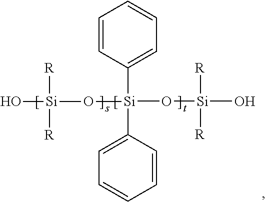
- the silanol terminated siloxane copolymer may be represented by:
- R may be a linear, branched, or cyclic saturated or unsaturated alkyl group containing from about 1 to 30 carbon atoms, s may be from about 1 to about 500, and t may be from about 1 to about 300.
- transfix blanket for a printer.
- the transfix blanket may include a substrate layer and a topcoat layer disposed on the substrate layer.
- the topcoat layer may include a silanol terminated copolymer crosslinked with at least one cross-linker.
- the at least one crosslinker may be one or more selected from the group consisting of tetraethoxysilane (TEOS), a trialkoxysilane terminated polydialkylsiloxane and/or one or more of a trialkoxysilyl terminated polymer.
- the silanol terminated copolymer may include from about 10 to about 25 mol % of a diphenylsiloxane repeat unit and greater than about 50 mol % of a dialkylsiloxane repeat unit.
- the silanol terminated siloxane copolymer may be represented by:
- R may be a linear, branched, or cyclic saturated or unsaturated alkyl group containing from about 1 to 30 carbon atoms, s may be from about 1 to about 500, and t may be from about 1 to about 300.
- Advantages can include one or more of the following: a coating formulation that is stable over time towards phase separation and gelation, a coating formulation that wets and cures on a wide variety of substrates, and a coating formulation that may be manufactured using non-toxic components using a chemistry that generates little waste.
- FIG. 1 depicts a schematic cross-sectional view of an illustrative transfix blanket for a printer, according to one or more embodiments.
- FIG. 2 depicts an illustrative printer including the transfix blanket, according to one or more embodiments.
- FIG. 3 depicts a schematic flowchart for forming an illustrative topcoat layer of a transfix blanket, according to one or more embodiments.
- FIG. 4 is an ATR-IR spectrum of an exemplary coating formed on a substrate.
- the word “printer” encompasses any apparatus that performs a print outputting function for any purpose, such as a digital copier, bookmaking machine, facsimile machine, a multi-function machine, electrostatographic device, etc.
- FIG. 1 depicts a schematic cross-sectional view of an illustrative transfix blanket 100 for a printer (e.g., an indirect aqueous inkjet printer), according to one or more embodiments disclosed.
- the blanket 100 may include a first or substrate layer 110 .
- the substrate layer 110 may be made from or include polyimide, aluminum, woven fabric, or combinations thereof.
- a second or conformance layer 120 may be disposed at least partially on and/or over the substrate layer 110 .
- the conformance layer 120 may have a depth or thickness 122 ranging from about 500 ⁇ m to about 7000 ⁇ m, about 1000 ⁇ m to about 5000 ⁇ m, or about 2000 ⁇ m to about 4000 ⁇ m.
- the conformance layer 120 may be made from a composite material. More particularly, the conformance layer 120 may be made from or include a polymer matrix.
- the polymer matrix may be or include silicone, a cross-linked silane, or a combination thereof.
- the conformance layer 120 may also include one or more filler materials such as silica, alumina, iron oxide, carbon black, or a combination thereof.
- the filler materials may be present in the conformance layer 120 in an amount ranging from about 0.1 wt % to about 20 wt %, about 1 wt % to about 15 wt %, or about 2 wt % to about 10 wt %.
- a third or tiecoat/adhesive layer 130 may be disposed at least partially on and/or over the conformance layer 120 .
- the adhesive layer 130 may have a depth or thickness 132 ranging from about 0.05 ⁇ m to about 10 ⁇ m, about 0.25 ⁇ m to about 5 ⁇ m, or about 0.5 ⁇ m to about 2 ⁇ m.
- the adhesive layer 130 may be made from a silane, an epoxy silane, an amino silane adhesive, or a combination thereof.
- the adhesive layer 130 may be made from a composite material. More particularly, the adhesive layer 130 may be made from or include a polymer matrix.
- the polymer matrix may be or include silicone, a cross-linked silane, or a combination thereof.
- a fourth or topcoat layer 140 may be disposed at least partially on and/or over the adhesive layer 130 .
- the topcoat layer 140 may have a depth or thickness 142 ranging from about 500 nm to about 200 ⁇ m, about 1 ⁇ m to about 150 ⁇ m, or about 5 ⁇ m to about 100 ⁇ m.
- the topcoat layer 140 may be made from a silanol terminated copolymer crosslinked with at least one cross-linker.
- the topcoat layer 140 may be formed from a liquid composition that is cured.
- the liquid composition may include the silanol terminated copolymer, and at least one cross-linker.
- the at least one cross-linker may be one or more selected from the group consisting of a trialkoxysilane terminated polydialkylsiloxane and one or more of a trialkoxysilyl terminated polymer.
- the liquid composition may further include a catalyst comprising about 0.1 wt % to about 5 wt % of the composition and selected from at least one in the group consisting of titanate, zirconate and tin.
- the liquid composition may be formed over a substrate, such as substrate layer 110 , and then cured to form the coating.
- the liquid composition may be cured at a temperature in the range of about 80° C. to about 150° C., such as about 90° C. to about 130° C., such as about 100° C. to about 120° C., for a time in the range of between about 10 minutes to about 90 minutes, such as about 30 minutes to about 70 minutes, such as about 40 minutes to about 60 minutes.
- the silanol terminated copolymer may comprise from about 10 mol % to about 25 mol %, from about 15 mol % to about 25 mol %, or from about 15 to about 20 mol % of a diphenylsiloxane repeat unit.
- the silanol terminated copolymer may comprise greater than about 50 mol %, greater than about 60 mol % or greater than about 70 mol % of a dialkylsiloxane repeat unit.
- the silanol terminated siloxane copolymer may comprise a molecular weight of between about 500 g/mol and about 50,000, g/mol, for example 500 g/mol and about 5000 g/mol, and may be represented by:
- R is a linear, branched, or cyclic saturated or unsaturated alkyl group containing from about 1 to 30 carbon atoms and s is from about 1 to about 500 and t is from about 1 to about 300.
- trialkoxysilane terminated polydialkylsiloxane may represented by
- R is a linear, branched, or cyclic saturated or unsaturated alkyl group containing from about 1 to 30 carbon atoms
- R′ is a hydrogen atom or a linear, branched, or cyclic saturated or unsaturated alkyl group containing from about 1 to 30 carbon atoms
- n is from about 0 to about 50
- q is from about 1 to about 500, from about 1 to about 200, or from about 1 to about 100.
- the one or more trialkoxysilyl terminated polymer may represented by formulae I or II:
- L 1 , L 2 and L 3 may be linker groups, such as, for example C 1 to C 6 alkyl bridge groups.
- X 1 , X 2 , X 3 , X 4 , X 5 , X 6 , X 7 , X 8 and X 9 may be independently selected from the group consisting of a hydroxyl, a reactive alkoxide functionality and an unreactive aliphatic functionality.
- R 1 and R 2 may be independently selected from the group consisting of: a) a linear, branched or cyclic, saturated or unsaturated alkyl group, b) a perfluorinated linear, branched or cyclic carbon chain, c) a group having one or more dialkylsiloxane units, d) a substituted or unsubstituted polyether group optionally comprising one or more amide moieties, carbonyl moieties, carboxylic acid ester moieties or amine moieties, and e) a polyamine group optionally comprising a saturated hydrocarbon chain moiety.
- the one or more trialkoxysilyl terminated polymer may be a trialkoxysilyl terminated polymer represented by formula (I) and may be a bis-trialkoxysilyl terminated polymer.
- suitable R 1 moieties may include, but are not limited to, the following:
- n is an integer ranging from 0 to 50
- x is an integer ranging from 0 to 30.
- the one or more trialkoxysilyl terminated polymer may be a trialkoxysilyl terminated polymer represented by formula (II).
- suitable R 2 moieties may include, but are not limited to, the following:
- a is an integer ranging from 0 to about 30, m and n are integers ranging from 0 to 50, and x is an integer ranging from 0 to 30.
- the one or more of a trialkoxysilyl terminated polymer includes a first trialkoxysilyl terminated polymer, a second trialkoxysilyl terminated polymer and a third trialkoxysilyl terminated polymer.
- the one or more of a trialkoxysilyl terminated polymer can further include a fourth trialkoxysilyl terminated polymer, a fifth trialkoxysilyl terminated polymer and/or a sixth trialkoxysilyl terminated polymer.
- the first, second, third, fourth, fifth and sixth trialkoxysilyl terminated polymer may each be a different trialkoxysilyl terminated polymer.
- each trialkoxysilyl terminated polymer may have a different structure.
- a liquid composition there may be from 1 trialkoxysilyl terminated polymer to 6 trialkoxysilyl terminated polymers, each having a different structure, or from 1 trialkoxysilyl terminated polymer to 4 trialkoxysilyl terminated polymers, each having a different structure, or from 1 trialkoxysilyl terminated polymer to 3 trialkoxysilyl terminated polymers, each having a different structure.
- formulae (I) and (II) may represent trialkoxysilyl terminated monomers or oligomers, and such monomers and/or oligomers may be used instead of or in addition to the one or more trialkoxysilyl terminated polymer in the liquid composition.
- the liquid composition may further include one or more of a solvent.
- the solvent may include one or more selected from organic hydrocarbon solvents, alcohols such as methanol, ethanol, isopropanol, and n-butanol and fluorinated solvents. Further examples of solvents include, but are not limited to, ketones such as methyl ethyl ketone, and methyl isobutyl ketone, and cyclohexanone. Mixtures of solvents may be used.
- the solvent may be a ketone solvent.
- the ketone solvent may be present in an amount of at least 1 weight percent of the formulation composition, such as from about 1 weight percent to about 60 weight percent, such as from about 3 weight percent to about 40 weight percent, or from about 5 weight percent to about 20 weight percent of the formulation composition.
- the coating may be polished to expose portions that are more hydrophilic than an upper surface thereof. For example, about 1.5 mm of the coating may be polished to expose the polar functional groups and provide a more wettable surface. While not limited to any particular theory it is believed that by exposing polar functional groups below the surface of the cured coatings, a surface free energy is increased.
- FIG. 2 depicts an illustrative printer 200 including the transfix blanket 100 , according to one or more embodiments disclosed.
- the printer 200 may be an indirect aqueous inkjet printer that forms an ink image on a surface of the blanket 100 .
- the blanket 100 may be mounted about an intermediate rotating member 212 .
- the ink image may be transferred from the blanket 100 to media passing through a nip 218 formed between the blanket 100 and a transfix roller 219 .
- a print cycle refers to operations of the printer 200 including, but not limited to, preparing an imaging surface for printing, ejecting ink onto the imaging surface, treating the ink on the imaging surface to stabilize and prepare the image for transfer to media, and transferring the image from the imaging surface to the media.
- the printer 200 may include a frame 211 that supports operating subsystems and components, which are described below.
- the printer 200 may also include an intermediate transfer member, which is illustrated as a rotating imaging drum 212 .
- the imaging drum 212 may have the blanket 100 mounted about the circumference of the drum 212 .
- the blanket 100 may move in a direction 216 as the member 212 rotates.
- the transfix roller 219 may rotate in the direction 217 and be loaded against the surface of blanket 100 to form the transfix nip 218 , within which ink images formed on the surface of blanket 100 are transfixed onto a print medium 249 .
- a heater in the drum 212 or in another location of the printer heats the blanket 100 to a temperature in a range of, for example, approximately 50° C. to approximately 70° C. The elevated temperature promotes partial drying of the liquid carrier that is used to deposit the hydrophilic composition and the water in the aqueous ink drops that are deposited on the blanket 100 .
- a surface maintenance unit (“SMU”) 292 may remove residual ink left on the surface of the blanket 100 after the ink images are transferred to the print medium 249 .
- the SMU 292 may include a coating applicator, such as a donor roller (not shown), which is partially submerged in a reservoir (not shown) that holds a hydrophilic polyurethane coating composition in a liquid carrier.
- the donor roller may rotate in response to the movement of the blanket 100 in the process direction.
- the donor roller may draw the liquid polyurethane composition from the reservoir and deposit a layer of the polyurethane composition on the blanket 100 .
- the polyurethane composition may be deposited as a uniform layer having any desired thickness.
- the dried polyurethane coating may substantially cover a surface of the blanket 100 before the printer 200 ejects ink drops during a print process.
- the SMU 292 may be operatively connected to a controller 280 , described in more detail below, to enable the controller 280 to operate the donor roller, as well as a metering blade and a cleaning blade to deposit and distribute the coating material onto the surface of the blanket 100 and to remove un-transferred ink and any polyurethane residue from the surface of the blanket 100 .
- the printer 200 may also include a dryer 296 that emits heat and optionally directs an air flow toward the polyurethane composition that is applied to the blanket 100 .
- the dryer 296 may facilitate the evaporation of at least a portion of the liquid carrier from the polyurethane composition to leave a dried layer on the blanket 100 before the intermediate transfer member passes one or more printhead modules 234 A- 234 D to receive the aqueous printed image.
- the printer 200 may also include an optical sensor 294 A, also known as an image-on-drum (“IOD”) sensor, which is configured to detect light reflected from the blanket 100 and the polyurethane coating applied to the blanket 100 as the member 212 rotates past the sensor.
- the optical sensor 294 A includes a linear array of individual optical detectors that are arranged in the cross-process direction across the blanket 100 .
- the optical sensor 294 A generates digital image data corresponding to light that is reflected from the blanket 100 and the polyurethane coating.
- the optical sensor 294 A generates a series of rows of image data, which are referred to as “scanlines,” as the intermediate transfer member 212 rotates the blanket 100 in the direction 216 past the optical sensor 294 A.
- each optical detector in the optical sensor 294 A may include three sensing elements that are sensitive to wavelengths of light corresponding to red, green, and blue (RGB) reflected light colors.
- the optical sensor 294 A may include illumination sources that shine red, green, and blue light.
- the sensor 294 A may have an illumination source that shines white light onto the surface of blanket 100 , and white light detectors are used.
- the optical sensor 294 A may shine complementary colors of light onto the image receiving surface to enable detection of different ink colors using the photodetectors.
- the image data generated by the optical sensor 294 A may be analyzed by the controller 280 or other processor in the printer 200 to identify the thickness of the polyurethane coating on the blanket 100 .
- the thickness and coverage may be identified from either specular or diffuse light reflection from the blanket 100 and/or the coating.
- Other optical sensors 294 B, 294 C, and 294 D may be similarly configured and located in different locations around the blanket 100 to identify and evaluate other parameters in the printing process, such as missing or inoperative inkjets and ink image formation prior to image drying ( 294 B), ink image treatment for image transfer ( 294 C), and the efficiency of the ink image transfer ( 294 D).
- some embodiments may include an optical sensor to generate additional data that may be used for evaluation of the image quality on the media ( 294 E).
- the printer 200 may include an airflow management system 201 , which generates and controls a flow of air through the print zone.
- the airflow management system 201 may include a printhead air supply 202 and a printhead air return 203 .
- the printhead air supply 202 and return 203 may be operatively connected to the controller 280 or some other processor in the printer 200 to enable the controller to manage the air flowing through the print zone. This regulation of the air flow may be through the print zone as a whole or about one or more printhead arrays.
- the regulation of the air flow may help to prevent evaporated solvents and water in the ink from condensing on the printhead and as well as attenuating heat in the print zone to reduce the likelihood that ink dries in the inkjets, which may clog the inkjets.
- the airflow management system 201 may also include one or more sensors to detect humidity and temperature in the print zone to enable more precise control of the temperature, flow, and humidity of the air supply 202 and return 203 to ensure optimum conditions within the print zone.
- the printer 200 may also include an aqueous ink supply and delivery subsystem 220 that has at least one source 222 of one color of aqueous ink. Since the printer 200 is a multicolor image producing machine, the ink delivery system 220 includes, for example, four (4) sources 222 , 224 , 226 , 228 , representing four (4) different colors CYMK (cyan, yellow, magenta, black) of aqueous inks.
- CYMK cyan, yellow, magenta, black
- the printhead system 230 may include a printhead support 232 , which provides support for a plurality of printhead modules, also known as print box units, 234 A- 234 D. Each printhead module 234 A- 234 D effectively extends across the width of the blanket 100 and ejects ink drops onto the blanket 100 .
- a printhead module 234 A- 234 D may include a single printhead or a plurality of printheads configured in a staggered arrangement.
- Each printhead module 234 A- 234 D may be operatively connected to a frame (not shown) and aligned to eject the ink drops to form an ink image on the coating on the blanket 100 .
- the printhead modules 234 A- 234 D may include associated electronics, ink reservoirs, and ink conduits to supply ink to the one or more printheads.
- One or more conduits may operatively connect the sources 222 , 224 , 226 , and 228 to the printhead modules 234 A- 234 D to provide a supply of ink to the one or more printheads in the modules 234 A- 234 D.
- each of the one or more printheads in a printhead module 234 A- 234 D may eject a single color of ink.
- the printheads may be configured to eject two or more colors of ink.
- printheads in modules 234 A and 234 B may eject cyan and magenta ink
- printheads in modules 234 C and 234 D may eject yellow and black ink.
- the printheads in the illustrated modules 234 A- 234 D are arranged in two arrays that are offset, or staggered, with respect to one another to increase the resolution of each color separation printed by a module. Such an arrangement enables printing at twice the resolution of a printing system only having a single array of printheads that eject only one color of ink.
- the printer 200 includes four printhead modules 234 A- 234 D, each of which has two arrays of printheads, alternative configurations include a different number of printhead modules or arrays within a module.
- the image dryer 204 may include a heater, such as a radiant infrared heater, a radiant near infrared heater, and/or a forced hot air convection heater 205 .
- the image dryer 204 may also include a dryer 206 , which is illustrated as a heated air source, and air returns 207 A and 207 B.
- the infrared heater 205 may apply infrared heat to the printed image on the surface of the blanket 100 to evaporate water or solvent in the ink.
- the heated air source 206 may direct heated air over the ink to supplement the evaporation of the water or solvent from the ink.
- the dryer 206 may be a heated air source with the same design as the dryer 296 . While the dryer 206 may be positioned along the process direction to dry the hydrophilic composition, the dryer 206 may also be positioned along the process direction after the printhead modules 234 A- 234 D to at least partially dry the aqueous ink on the blanket 100 . The air may then be collected and evacuated by air returns 207 A and 207 B to reduce the interference of the air flow with other components in the printing area.
- the printer 200 may further include a print medium supply and handling system 240 that stores, for example, one or more stacks of paper print mediums of various sizes.
- the print medium supply and handling system 240 includes sheet or substrate supply sources 242 , 244 , 246 , and 248 .
- the supply source 248 may be a high capacity paper supply or feeder for storing and supplying image receiving substrates in the form of cut print mediums 249 .
- the print medium supply and handling system 240 may also include a substrate handling and transport system 250 that has a media pre-conditioner assembly 252 and a media post-conditioner assembly 254 .
- the printer 200 may also include a fusing device 260 to apply additional heat and pressure to the print medium after the print medium passes through the transfix nip 218 .
- the printer 200 may also include an original document feeder 270 that has a document holding tray 272 , document sheet feeding and retrieval devices 274 , and a document exposure and scanning system 276 .
- the controller 80 may be operably connected to the intermediate transfer member 212 , the printhead modules 234 A- 234 D (and thus the printheads), the substrate supply and handling system 240 , the substrate handling and transport system 250 , and, in some embodiments, the one or more optical sensors 294 A- 294 E.
- the controller 280 may be a self-contained, dedicated mini-computer having a central processor unit (“CPU”) 282 with electronic storage 284 , and a display or user interface (“UI”) 286 .
- the controller 280 may include a sensor input and control circuit 288 as well as a pixel placement and control circuit 289 .
- the CPU 282 may read, capture, prepare, and manage the image data flow between image input sources, such as the scanning system 276 , or an online or a work station connection 290 , and the printhead modules 234 A- 234 D.
- the controller 280 may be the main multi-tasking processor for operating and controlling all of the other machine subsystems and functions.
- the printer 200 may operate components within the printer 200 to perform a process for transferring and fixing the image or images from the blanket 100 to media.
- the controller 280 may operate actuators to drive one or more of the rollers 264 in the media transport system 250 to move the print medium 249 in the process direction P to a position adjacent the transfix roller 219 and then through the transfix nip 218 between the transfix roller 219 and the blanket 100 .
- the transfix roller 219 may apply pressure against the back side of the print medium 249 in order to press the front side of the print medium 249 against the blanket 100 and the intermediate transfer member 212 .
- the transfix roller 219 may also be heated, as shown, the transfix roller 219 is unheated in FIG. 2 .
- the pre-heater assembly 252 for the print medium 249 may be in the media path leading to the transfix nip 218 .
- the pre-conditioner assembly 252 may condition the print medium 249 to a predetermined temperature that aids in the transferring of the image to the media, thus simplifying the design of the transfix roller 219 .
- the pressure produced by the transfix roller 219 on the back side of the heated print medium 249 may facilitate the transfixing (transfer and fusing) of the image from the intermediate transfer member 212 onto the print medium 249 .
- the rotation or rolling of both the intermediate transfer member 212 and transfix roller 219 not only transfixes the images onto the print medium 249 , but also assists in transporting the print medium 249 through the transfix nip 218 .
- the intermediate transfer member 212 may continue to rotate to enable the printing process to be repeated.
- the image receiving surface passes a cleaning unit that removes residual portions of the sacrificial polyurethane coating and small amounts of residual ink from the image receiving surface of the blanket 100 .
- the cleaning unit is embodied as a cleaning blade 295 that engages the surface of the blanket 100 .
- the blade 295 is formed from a material that wipes the surface of the blanket 100 without causing damage to the blanket 100 .
- the cleaning blade 295 may be formed from a flexible polymer material in the printer 200 .
- the cleaning unit may include a roller or other member that applies a mixture of water and detergent to remove residual materials from the surface of the blanket 100 after the intermediate transfer member moves through the transfix nip 218 .
- the term “detergent” or cleaning agent refers to any surfactant, solvent, or other chemical compound that is suitable for removing any sacrificial polyurethane coating and any residual ink from the image receiving surface of the blanket 100 .
- FIG. 3 depicts a schematic flowchart 300 for forming an illustrative coating, such as topcoat layer 140 of a transfix blanket 100 , according to one or more embodiments. More particularly, the flowchart 300 describes the formulation and drawdown coating of a silanol terminated copolymer which is cured and crosslinked to at least one crosslinker.
- Silanol terminated dimethylsiloxane-diphenylsiloxane copolymer (3.92 g; available from Gelest, Inc., Morrisville, Pa.), polydiethoxysilane (1.31 g, available from Gelest, Inc., Morrisville, Pa.) and triethoxysilyl terminated polydimethylsiloxane (1.31 g, available from Gelest, Inc., Morrisville, Pa.) are combined in a vial and mixed by vortex for 10 s at 2500 rpm as shown in 302 .
- Cyclohexanone (0.25 g) is added to the vial as shown in 303 , followed by addition of titanium acetylacetonate (0.44 g of a 75% active solution in IPA; 5 wt % active catalyst relative to all siloxanes; available from Sigma-Aldrich Co., LLC, St. Louis, Mo.) as shown in 304 .
- the solution is mixed by vortex for 10 s at 2500 rpm as shown in 306 .
- the coating solution is filtered through a 0.45 ⁇ m PTFE filter immediately prior to coating to remove any particulates as shown in 307 .
- the coating solution is draw down coated on polyimide or aluminum or silicone or Mylar substrates or cast onto quartz yielding uniform coatings as shown in 308 .
- the coating solution formed a stable wet layer on all substrates tested.
- the coatings are cured at 130° C. for 1 hour as shown in 310 , yielding clear, uniform films.
- Silanol terminated dimethylsiloxane-diphenylsiloxane copolymer (1.52 g), triethoxysilylethyl terminated polydimethylsiloxane (0.57 g), N,N′-bis-[(3-triethoxysilylpropyl)aminocarbonyl]polyethylene oxide (10-15 EO) (0.37 g), and 3-(trimethoxysilylpropyl)diethylenetriamine (0.57 g) are combined in a vial and mixed by vortex for 10 s at 2500 rpm.
- Cyclohexanone (0.27 g) is added to the vial, followed by titanium acetylacetonate (0.20 g of a 75% active solution in IPA; 5 wt % active catalyst relative to all siloxanes).
- the solution is mixed by vortex for 10 s at 2500 rpm.
- the coating solution is filtered through a 0.45 ⁇ m PTFE filter immediately prior to coating to remove any particulates.
- the coating solution is draw down coated on polyimide or aluminum or silicone or Mylar substrates or cast onto quartz yielding uniform coatings.
- the coating solution formed a stable wet layer on all substrates tested.
- the coatings are cured at 90° C. with ⁇ 50% relative humidity for 1 h to give clear, uniform films.
- silanol terminated dimethylsiloxane-diphenylsiloxane copolymer (1.12 g), N,N′-bis-[(3-triethoxysilylpropyl)aminocarbonyl]polyethylene oxide (10-15 EO) (0.37 g), and 3-(trimethoxysilylpropyl)diethylenetriamine (0.60 g) are combined in a vial and mixed by vortex for 10 s at 2500 rpm.
- Cyclohexanone (0.33 g) is added to the vial, followed by titanium acetylacetonate (0.14 g of a 75% active solution in IPA; 5 wt % active catalyst relative to all siloxanes).
- the solution is mixed by vortex for 10 s at 2500 rpm.
- the coating solution is filtered through a 0.45 ⁇ m PTFE filter immediately prior to coating to remove any particulates.
- the coating solution is draw down coated on polyimide or aluminum or silicone or Mylar substrates or cast onto quartz yielding uniform coatings.
- the coating solution formed a stable wet layer on all substrates tested.
- the coatings are cured at 90° C. with ⁇ 50% relative humidity for 1 h to give clear, uniform films.
- Silanol terminated dimethylsiloxane-diphenylsiloxane copolymer (1.51 g), triethoxysilylethyl terminated polydimethylsiloxane (0.57 g), 2-(acetoxy(polyethyleneoxy)propyl)triethoxysilane (0.37 g), and 3-(trimethoxysilylpropyl)diethylenetriamine (0.60 g) are combined in a vial and mixed by vortex for 10 s at 2500 rpm.
- Cyclohexanone (0.26 g) is added to the vial, followed by titanium acetylacetonate (0.21 g of a 75% active solution in IPA; 5 wt % active catalyst relative to all siloxanes).
- the solution is mixed by vortex for 10 s at 2500 rpm.
- the coating solution is filtered through a 0.45 ⁇ m PTFE filter immediately prior to coating to remove any particulates.
- the coating solution is drawdown coated on polyimide or aluminum or silicone or Mylar substrates or cast onto quartz yielding uniform coatings.
- the coating solution formed a stable wet layer on all substrates tested.
- the coatings are cured at 90° C. with ⁇ 50% relative humidity for 1 h to give clear, uniform films.
- the coating is cleaned with isopropyl alcohol and the substrate is affixed to a hard surface with double sided tape.
- Lapping film (9 ⁇ m) is attached to a sanding block and the coating is sanded using moderate pressure in a circular motion for ⁇ 1 min to remove 1-3 ⁇ m of material. After removing the desired amount of material excess dust is blown from the coating with compressed air.
- Colloidal alumina suspension (0.05 ⁇ m particles Allied High Tech Products) is applied to the film and a polishing cloth (Allied High Tech Products, Chem-Pol adhesive backed polishing cloth) is used to vigorously rub the colloidal material in a circular motion for ⁇ 5 min.
- the coating is rinsed repeatedly with de-ionized water and dried at 55° C. for 1 h. Polishing with colloidal alumina removed the larger surface roughness features.
- composition of the bulk is homogeneous as the OH and NH stretching between 3,000-3,500 cm ⁇ 1 are observed in similar intensity throughout the bulk of the coating ( FIG. 4 ). Accordingly, the surface polishing step described in Example 5 enables exposure of a more hydrophilic portions of the coating relative to the surface of the coating which allows for improved wetting.
Abstract
Description

where R may be a linear, branched, or cyclic saturated or unsaturated alkyl group containing from about 1 to 30 carbon atoms, s may be from about 1 to about 500, and t may be from about 1 to about 300.
wherein R may be a linear, branched, or cyclic saturated or unsaturated alkyl group containing from about 1 to 30 carbon atoms, s may be from about 1 to about 500, and t may be from about 1 to about 300.

where R is a linear, branched, or cyclic saturated or unsaturated alkyl group containing from about 1 to 30 carbon atoms and s is from about 1 to about 500 and t is from about 1 to about 300.

wherein R is a linear, branched, or cyclic saturated or unsaturated alkyl group containing from about 1 to 30 carbon atoms, R′ is a hydrogen atom or a linear, branched, or cyclic saturated or unsaturated alkyl group containing from about 1 to 30 carbon atoms, n is from about 0 to about 50 and q is from about 1 to about 500, from about 1 to about 200, or from about 1 to about 100.


where a is an integer ranging from 0 to about 30, n is an integer ranging from 0 to 50, and x is an integer ranging from 0 to 30.

where a is an integer ranging from 0 to about 30, m and n are integers ranging from 0 to 50, and x is an integer ranging from 0 to 30.
Claims (7)


Priority Applications (3)
| Application Number | Priority Date | Filing Date | Title |
|---|---|---|---|
| US14/219,653 US9683130B2 (en) | 2014-03-19 | 2014-03-19 | Polydiphenylsiloxane coating formulation and method for forming a coating |
| JP2015045345A JP2015178617A (en) | 2014-03-19 | 2015-03-06 | Polydiphenylsiloxane coating formulation and method for forming coating |
| US15/595,884 US10081739B2 (en) | 2014-03-19 | 2017-05-15 | Polydiphenylsiloxane coating formulation and method for forming a coating |
Applications Claiming Priority (1)
| Application Number | Priority Date | Filing Date | Title |
|---|---|---|---|
| US14/219,653 US9683130B2 (en) | 2014-03-19 | 2014-03-19 | Polydiphenylsiloxane coating formulation and method for forming a coating |
Related Child Applications (1)
| Application Number | Title | Priority Date | Filing Date |
|---|---|---|---|
| US15/595,884 Division US10081739B2 (en) | 2014-03-19 | 2017-05-15 | Polydiphenylsiloxane coating formulation and method for forming a coating |
Publications (2)
| Publication Number | Publication Date |
|---|---|
| US20150267078A1 US20150267078A1 (en) | 2015-09-24 |
| US9683130B2 true US9683130B2 (en) | 2017-06-20 |
Family
ID=54141488
Family Applications (2)
| Application Number | Title | Priority Date | Filing Date |
|---|---|---|---|
| US14/219,653 Active 2035-06-03 US9683130B2 (en) | 2014-03-19 | 2014-03-19 | Polydiphenylsiloxane coating formulation and method for forming a coating |
| US15/595,884 Active US10081739B2 (en) | 2014-03-19 | 2017-05-15 | Polydiphenylsiloxane coating formulation and method for forming a coating |
Family Applications After (1)
| Application Number | Title | Priority Date | Filing Date |
|---|---|---|---|
| US15/595,884 Active US10081739B2 (en) | 2014-03-19 | 2017-05-15 | Polydiphenylsiloxane coating formulation and method for forming a coating |
Country Status (2)
| Country | Link |
|---|---|
| US (2) | US9683130B2 (en) |
| JP (1) | JP2015178617A (en) |
Families Citing this family (19)
| Publication number | Priority date | Publication date | Assignee | Title |
|---|---|---|---|---|
| US9683130B2 (en) | 2014-03-19 | 2017-06-20 | Xerox Corporation | Polydiphenylsiloxane coating formulation and method for forming a coating |
| US9494884B2 (en) | 2014-03-28 | 2016-11-15 | Xerox Corporation | Imaging plate coating composite composed of fluoroelastomer and aminosilane crosslinkers |
| US9428663B2 (en) | 2014-05-28 | 2016-08-30 | Xerox Corporation | Indirect printing apparatus employing sacrificial coating on intermediate transfer member |
| US9550908B2 (en) | 2014-09-23 | 2017-01-24 | Xerox Corporation | Sacrificial coating for intermediate transfer member of an indirect printing apparatus |
| US9593255B2 (en) | 2014-09-23 | 2017-03-14 | Xerox Corporation | Sacrificial coating for intermediate transfer member of an indirect printing apparatus |
| US9611404B2 (en) | 2014-09-23 | 2017-04-04 | Xerox Corporation | Method of making sacrificial coating for an intermediate transfer member of indirect printing apparatus |
| US9421758B2 (en) | 2014-09-30 | 2016-08-23 | Xerox Corporation | Compositions and use of compositions in printing processes |
| US9956760B2 (en) | 2014-12-19 | 2018-05-01 | Xerox Corporation | Multilayer imaging blanket coating |
| US9458341B2 (en) | 2015-02-12 | 2016-10-04 | Xerox Corporation | Sacrificial coating compositions comprising polyvinyl alcohol and waxy starch |
| US9816000B2 (en) | 2015-03-23 | 2017-11-14 | Xerox Corporation | Sacrificial coating and indirect printing apparatus employing sacrificial coating on intermediate transfer member |
| US9815271B2 (en) * | 2015-07-28 | 2017-11-14 | Canon Kabushiki Kaisha | Intermediate transfer member, image recording apparatus, and image recording method |
| US9718964B2 (en) | 2015-08-19 | 2017-08-01 | Xerox Corporation | Sacrificial coating and indirect printing apparatus employing sacrificial coating on intermediate transfer member |
| US10391761B2 (en) * | 2016-11-28 | 2019-08-27 | Océ Holding B.V. | Printing assembly for direct and indirect inkjet printing |
| JP2018144358A (en) | 2017-03-06 | 2018-09-20 | キヤノン株式会社 | Ink jet recording apparatus and recording method for the same |
| US11478991B2 (en) | 2020-06-17 | 2022-10-25 | Xerox Corporation | System and method for determining a temperature of an object |
| US11499873B2 (en) | 2020-06-17 | 2022-11-15 | Xerox Corporation | System and method for determining a temperature differential between portions of an object printed by a 3D printer |
| US11498354B2 (en) | 2020-08-26 | 2022-11-15 | Xerox Corporation | Multi-layer imaging blanket |
| US11767447B2 (en) | 2021-01-19 | 2023-09-26 | Xerox Corporation | Topcoat composition of imaging blanket with improved properties |
| CN114146581B (en) * | 2021-10-22 | 2022-06-24 | 南京工业大学 | Phenyl-modified PDMS separation membrane, preparation method and application thereof in aromatic compound separation |
Citations (145)
| Publication number | Priority date | Publication date | Assignee | Title |
|---|---|---|---|---|
| US4339553A (en) | 1979-08-14 | 1982-07-13 | Daikin Kogyo Co., Ltd. | Water-based fluoroelastomer coating composition |
| US4970098A (en) | 1990-04-18 | 1990-11-13 | International Business Machines Corporation | Coatings for hot roll fusers |
| US4997642A (en) | 1981-12-24 | 1991-03-05 | Sandoz Ltd. | Stable oil-in-water emulsions |
| US5145518A (en) | 1990-06-27 | 1992-09-08 | Xerox Corporation | Inks containing block copolymer micelles |
| US5146087A (en) | 1991-07-23 | 1992-09-08 | Xerox Corporation | Imaging process with infrared sensitive transparent receiver sheets |
| US5202265A (en) | 1991-10-24 | 1993-04-13 | Xerox Corporation | Toner taggant processes |
| US5208630A (en) | 1991-11-04 | 1993-05-04 | Xerox Corporation | Process for the authentication of documents utilizing encapsulated toners |
| US5225900A (en) | 1990-12-31 | 1993-07-06 | Xerox Corporation | Method of storing information within a reproduction system |
| US5231135A (en) | 1989-09-05 | 1993-07-27 | Milliken Research Corporation | Lightfast colored polymeric coatings and process for making same |
| US5256193A (en) | 1992-06-25 | 1993-10-26 | Xerox Corporation | Porphyrin chromophore and dendrimer ink composition |
| US5271764A (en) | 1992-02-12 | 1993-12-21 | Xerox Corporation | Ink compositions |
| US5275647A (en) | 1991-11-25 | 1994-01-04 | Xerox Corporation | Ink compositions |
| US5286286A (en) | 1991-05-16 | 1994-02-15 | Xerox Corporation | Colorless fast-drying ink compositions for printing concealed images detectable by fluorescence |
| US5378574A (en) | 1988-08-17 | 1995-01-03 | Xerox Corporation | Inks and liquid developers containing colored silica particles |
| US5385803A (en) | 1993-01-04 | 1995-01-31 | Xerox Corporation | Authentication process |
| US5464703A (en) | 1994-06-29 | 1995-11-07 | Eastman Kodak Company | Tin oxide filled dimethylsiloxane-fluoroalkylsiloxane fuser roll for fixing toner to a substrate |
| US5474852A (en) | 1994-06-29 | 1995-12-12 | Eastman Kodak Company | Tin oxide filled diphenylsiloxane-dimethylsiloxane fuser member for fixing toner to a substrate |
| US5494702A (en) | 1994-06-21 | 1996-02-27 | Alco Industries, Inc. | Protective solvent free liquid masking compounds and related method |
| US5539038A (en) | 1994-10-03 | 1996-07-23 | Rexham Graphics, Inc. | Ink jet ink and process for making same |
| US5543177A (en) | 1992-11-05 | 1996-08-06 | Xerox Corporation | Marking materials containing retroreflecting fillers |
| US5547759A (en) | 1993-12-09 | 1996-08-20 | Eastman Kodak Company | Coated fuser members and methods of making coated fuser members |
| US5554480A (en) | 1994-09-01 | 1996-09-10 | Xerox Corporation | Fluorescent toner processes |
| US5593807A (en) | 1996-05-10 | 1997-01-14 | Xerox Corporation | Toner processes using sodium sulfonated polyester resins |
| US5621022A (en) | 1992-11-25 | 1997-04-15 | Tektronix, Inc. | Use of polymeric dyes in hot melt ink jet inks |
| US5629416A (en) | 1995-03-31 | 1997-05-13 | National Starch And Chemical Investment Holding Corporation | Method of preparing crosslinked starch esters |
| US5695878A (en) | 1996-03-28 | 1997-12-09 | Xerox Corporation | Fluoroelastomer members |
| US5700568A (en) | 1996-03-28 | 1997-12-23 | Xerox Corporation | Fluoroelastomer members |
| US5736520A (en) | 1988-10-07 | 1998-04-07 | Merrell Pharmaceuticals Inc. | Peptidase inhibitors |
| US5744200A (en) | 1996-03-28 | 1998-04-28 | Xerox Corporation | Volume grafted elastomer surfaces and methods thereof |
| US5750204A (en) | 1996-03-28 | 1998-05-12 | Xerox Corporation | Fluoroelastomer surfaces and methods thereof |
| US5753307A (en) | 1996-03-28 | 1998-05-19 | Xerox Corporation | Fluoroelastomer surfaces and methods thereof |
| US5808645A (en) | 1992-11-25 | 1998-09-15 | Tektronix, Inc. | Removable applicator assembly for applying a liquid layer |
| US5841456A (en) | 1991-08-23 | 1998-11-24 | Seiko Epson Corporation | Transfer printing apparatus with dispersion medium removal member |
| US5945245A (en) | 1998-01-13 | 1999-08-31 | Xerox Corporation | Toner processes |
| US6020300A (en) | 1996-09-16 | 2000-02-01 | The Procter & Gamble Company | Composition for treating stains on laundry items and methods of treatment |
| US6042227A (en) | 1998-05-19 | 2000-03-28 | Xerox Corporation | Hot melt phase change ink containing Diels-Alder polymerization precursor |
| US6051562A (en) | 1993-09-15 | 2000-04-18 | Ciba Specialty Chemical Water Treatment Limited | Stabilization and use of heterogeneous liquid compositions |
| US6103815A (en) | 1998-02-17 | 2000-08-15 | Xerox Corporation | Fluorinated carbon filled latex fluorocarbon elastomer |
| US6156858A (en) | 1997-06-25 | 2000-12-05 | Xerox Corporation | Stable free radical polymerization processes |
| US6221137B1 (en) | 1999-06-18 | 2001-04-24 | Xerox Corporation | Metal phthalocyanine colorants for phase change inks |
| US6348509B1 (en) | 1998-09-07 | 2002-02-19 | Rohm And Haas Company | Method of inhibiting the formation of oil and water emulsions |
| US20020064648A1 (en) | 2000-11-29 | 2002-05-30 | Schlueter Edward L. | Three layer seamless transfer component |
| US20030067528A1 (en) | 2001-10-09 | 2003-04-10 | Nexpress Solutions Llc | Ink jet process including removal of excess liquid from an intermediate member |
| US6586100B1 (en) | 1998-12-16 | 2003-07-01 | Nexpress Solutions Llc | Fluorocarbon-silicone interpenetrating network useful as fuser member coating |
| US20030234840A1 (en) | 2002-06-20 | 2003-12-25 | Xerox Corporation | Phase change ink imaging component with outer layer having haloelastomer with pendant chains |
| US20030233953A1 (en) | 2002-06-20 | 2003-12-25 | Xerox Corporation | Phase change ink imaging component with fluorosilicone layer |
| US20030233952A1 (en) | 2002-06-20 | 2003-12-25 | Xerox Corporation | Phase change ink imaging component with thermoplastic layer |
| US20040158056A1 (en) | 2001-04-26 | 2004-08-12 | Hiemstra Hendrik Cornelis | Cross-linking of starch |
| US20040253436A1 (en) | 2003-06-13 | 2004-12-16 | Xerox Corporation | Fuser member having platinum catalyzed addition cured silicone layer |
| US20050018027A1 (en) | 1998-10-23 | 2005-01-27 | Xerox Corporation | Phase change ink imaging component having elastomer outer layer |
| WO2005047385A1 (en) | 2003-11-07 | 2005-05-26 | Cargill, Incorporated | Starch compositions and use in cellulosic webs and coatings |
| US20060008599A1 (en) | 2004-07-12 | 2006-01-12 | Konica Minolta Photo Imaging, Inc. | Manufacturing method of ink jet recording paper and ink jet recording paper |
| US20060105117A1 (en) | 2004-11-15 | 2006-05-18 | Kim Won K | Biaxial-optical polynorbornene-based film and method of manufacturing the same, integrated optical compensation polarizer having the film and method of manufacturing the polarizer, and liquid crystal display panel containing the film and/or polarizer |
| US20060147659A1 (en) | 2005-01-06 | 2006-07-06 | Arkwright, Inc. | Ink-jet media having supporting intermediate coatings and microporous top coatings |
| US20060152566A1 (en) | 2003-06-23 | 2006-07-13 | Hiroshi Taniuchi | Image forming method, image formng apparatus, intermediate transfer body, method of modifying surface of intermediate transfer body |
| US7172276B2 (en) | 2004-12-10 | 2007-02-06 | Xerox Corporation | Heterogeneous low energy gel ink composition |
| US7202883B2 (en) | 2004-12-10 | 2007-04-10 | Xerox Corporation | Heterogeneous reactive ink composition |
| US20070207186A1 (en) | 2006-03-04 | 2007-09-06 | Scanlon John J | Tear and abrasion resistant expanded material and reinforcement |
| US20070207269A1 (en) | 2004-06-14 | 2007-09-06 | Cal-West Specialty Coatings, Inc. | Masking solutions comprising siloxane-based surfactants for using in painting operations |
| US7281790B2 (en) | 2003-11-20 | 2007-10-16 | Canon Kabushiki Kaisha | Ink-jet recording method and ink-jet recording apparatus |
| US7294377B2 (en) | 2004-11-15 | 2007-11-13 | Xerox Corporation | Fluoroelastomer members and curing methods using biphenyl and amino silane having amino functionality |
| US20070266896A1 (en) * | 2004-06-11 | 2007-11-22 | Toray Industries, Inc. | Siloxane-Based Coating Material, Optical Article, and Production Method of Siloxane-Based Coating Material |
| US20080032072A1 (en) | 2006-06-15 | 2008-02-07 | Canon Kabushiki Kaisha | Method of producing recorded product (printed product) and image forming apparatus |
| US20080055381A1 (en) | 2006-09-01 | 2008-03-06 | Fuji Xerox Co., Ltd. | Ink-recipient particle, material for recording, recording apparatus and storage member for ink-recipient particle |
| EP1900527A1 (en) | 2000-10-10 | 2008-03-19 | Lexmark International, Inc. | Intermediate transfer medium coating solution and method of ink jet printing coating solution |
| US7374812B2 (en) | 2004-12-30 | 2008-05-20 | 3M Innovative Properties Company | Low refractive index coating composition for use in antireflection polymer film coatings and manufacturing method |
| US20080206571A1 (en) | 2007-02-27 | 2008-08-28 | Berckmans Marc Charles F | Coating compositions |
| US20090110942A1 (en) | 2004-10-18 | 2009-04-30 | Rulande Henderson-Rutgers | Barrier film |
| US20090152664A1 (en) | 2007-04-18 | 2009-06-18 | Ethan Jacob Dukenfield Klem | Materials, Systems and Methods for Optoelectronic Devices |
| US20090195579A1 (en) | 2008-02-06 | 2009-08-06 | Tousi Susan H | Inkjet printing system and method of printing |
| US20090237479A1 (en) | 2008-03-24 | 2009-09-24 | Fuji Xerox Co., Ltd. | Recording apparatus |
| US7608325B2 (en) | 2006-09-20 | 2009-10-27 | Xerox Corporation | Fuser member having conductive fluorocarbon outer layer |
| US7767011B2 (en) | 2005-05-31 | 2010-08-03 | Xerox Corporation | Aqueous gel ink compositions and method of printing same |
| US7780286B2 (en) | 2006-03-30 | 2010-08-24 | Fujifilm Corporation | Image forming apparatus and image forming method |
| EP2228690A1 (en) | 2009-03-11 | 2010-09-15 | Xerox Corporation | Self-releasing nanoparticle fillers in fusing members |
| US20110018925A1 (en) | 2009-07-23 | 2011-01-27 | Canon Kabushiki Kaisha | Printing apparatus and control method thereof |
| US20110025752A1 (en) | 2009-07-29 | 2011-02-03 | Xerox Corporation | Fabrication of improved aluminum rollers with low adhesion and ultra/super hydrophobicity and/or oleophobicity by electrospinning technique in solid ink-jet marking |
| US20110122195A1 (en) | 2009-11-24 | 2011-05-26 | Kovacs Gregory J | Coating For An Ink Jet Printhead Front Face |
| US20110122210A1 (en) | 2009-11-24 | 2011-05-26 | Xerox Corporation. | Image Conditioning Coating |
| US8038284B2 (en) | 2007-09-05 | 2011-10-18 | Fujifilm Corporation | Liquid application apparatus and method, and image forming apparatus |
| US20110269849A1 (en) | 2010-05-03 | 2011-11-03 | Yuan Yao | Emulsions and Methods for the Preparation Thereof, and Methods for Improving Oxidative Stability of Lipids |
| US20120039648A1 (en) | 2010-08-12 | 2012-02-16 | Xerox Corporation | Low adhesion coatings for image fixing |
| US20120042518A1 (en) | 2010-08-20 | 2012-02-23 | Xerox Corporation | Method for applying nanocoatings with easy clean and self-clean capability on a printhead |
| US8136936B2 (en) | 2007-08-20 | 2012-03-20 | Moore Wallace North America, Inc. | Apparatus and methods for controlling application of a substance to a substrate |
| US8142557B2 (en) | 2006-06-28 | 2012-03-27 | Xerox Corporation | Radiation curable ink containing gellant and radiation curable wax |
| US20120083530A1 (en) | 2010-04-09 | 2012-04-05 | Martek Biosciences Corporation | Thermally Stable Oil-in-Water Emulsions Containing an Oil That Contains Polyunsaturated Fatty Acids |
| US20120103212A1 (en) | 2010-10-29 | 2012-05-03 | Palo Alto Research Center Incorporated | Variable Data Lithography System |
| US20120121827A1 (en) | 2010-11-12 | 2012-05-17 | Baird David G | Transparent ink-jet recording films, compositions, and methods |
| US20120135650A1 (en) | 1996-01-25 | 2012-05-31 | Innovia Films Limited | Printable film |
| US20120140009A1 (en) | 2010-12-03 | 2012-06-07 | Canon Kabushiki Kaisha | Transfer type inkjet recording method |
| US20120162312A1 (en) | 2009-11-24 | 2012-06-28 | Xerox Corporation | Coating For An Ink Jet Printhead Front Face |
| US8215762B2 (en) | 2009-03-26 | 2012-07-10 | Fuji Xerox Co., Ltd. | Recording apparatus that forms ink receiving layer(s) on an intermediate transfer body and recording method thereof |
| US8247066B2 (en) | 2009-05-06 | 2012-08-21 | Xerox Corporation | Teflon fuser member containing fluorinated nano diamonds |
| US8268399B2 (en) | 2009-08-19 | 2012-09-18 | Xerox Corporation | Polyhedral oligomeric silsesquioxane image conditioning coating |
| US20120251685A1 (en) | 2011-04-04 | 2012-10-04 | Martek Biosciences Corporation | Oil-in-Water Emulsions Comprising a Polyunsaturated Fatty Acid and Methods of Making the Same |
| US20120274914A1 (en) | 2011-04-27 | 2012-11-01 | Palo Alto Research Center Incorporated | Variable Data Lithography System for Applying Multi-Component Images and Systems Therefor |
| US20120283098A1 (en) | 2011-05-05 | 2012-11-08 | Dow Agrosciences Llc | Stable high strength oil-in-water emulsions |
| US20120301818A1 (en) | 2011-05-27 | 2012-11-29 | Xerox Corporation | Protective coatings for bias charge rollers |
| US8350879B2 (en) | 2009-11-02 | 2013-01-08 | Xerox Corporation | Non-contact heating of solid ink prints after ink fixing |
| US8500269B2 (en) | 2009-12-16 | 2013-08-06 | Canon Kabushiki Kaisha | Image forming method and image forming apparatus for forming an image on an intermediate transfer medium |
| US20130266803A1 (en) | 2012-04-05 | 2013-10-10 | Xerox Corporation | Fuser member |
| US20130272763A1 (en) | 2012-04-13 | 2013-10-17 | Xerox Corporation | Bionanocomposite fuser topcoats comprising nanosized cellulosic particles |
| US20140060359A1 (en) | 2012-08-31 | 2014-03-06 | Xerox Corporation | Imaging member for offset printing applications |
| US20140060352A1 (en) | 2012-08-31 | 2014-03-06 | Xerox Corporation | Imaging member for offset printing applications |
| US20140060361A1 (en) | 2012-08-31 | 2014-03-06 | Xerox Corporation | Imaging member for offset printing applications |
| US20140060363A1 (en) | 2012-08-31 | 2014-03-06 | Xerox Corporation | Imaging member for offset printing applications |
| US20140060357A1 (en) | 2012-08-31 | 2014-03-06 | Palo Alto Research Center Inc. | Imaging member |
| US20140060360A1 (en) | 2012-08-31 | 2014-03-06 | Palo Alto Research Center Inc. | Textured imaging member |
| US20140060365A1 (en) | 2012-08-31 | 2014-03-06 | Xerox Corporation | Imaging member for offset printing applications |
| US20140154377A1 (en) | 2011-04-04 | 2014-06-05 | Dsm Ip Assets B.V. | Oil-in-water emulsions comprising a polyunsaturated fatty acid and methods of making the same |
| US20140168330A1 (en) | 2012-12-17 | 2014-06-19 | Xerox Corporation | Wetting enhancement coating on intermediate transfer member (itm) for aqueous inkjet intermediate transfer architecture |
| US20140307800A1 (en) | 2013-04-12 | 2014-10-16 | Qualcomm Incorporated | Rice parameter update for coefficient level coding in video coding process |
| US8919252B2 (en) | 2012-08-31 | 2014-12-30 | Xerox Corporation | Methods and systems for ink-based digital printing with multi-component, multi-functional fountain solution |
| US20150004861A1 (en) | 2013-06-30 | 2015-01-01 | Xerox Corporation | Grafted polymers as oleophobic or hydrophobic coatings |
| US20150022602A1 (en) | 2012-03-05 | 2015-01-22 | Landa Corporation Ltd. | Printing system |
| US20150031806A1 (en) * | 2013-07-24 | 2015-01-29 | Momentive Performance Materials Inc. | Moisture curable compositions with enhanced elongation and tear strentgh properties |
| US20150085039A1 (en) | 2013-09-20 | 2015-03-26 | Xerox Corporation | Coating for Aqueous Inkjet Transfer |
| US20150085036A1 (en) | 2013-09-20 | 2015-03-26 | Xerox Corporation | Coating for Aqueous Inkjet Transfer |
| US9011594B1 (en) | 2013-09-30 | 2015-04-21 | Xerox Corporation | Methods for forming functionalized carbon black with amino-terminated polyfluorodimethylsiloxane for printing |
| US20150116414A1 (en) | 2013-10-30 | 2015-04-30 | Xerox Corporation | Ink Jet Ink For Indirect Printing Applications |
| US20150119510A1 (en) | 2013-10-30 | 2015-04-30 | Xerox Corporation | Inkjet ink containing polystyren copolymer latex suitable for indirect printing |
| US9022546B1 (en) | 2013-11-25 | 2015-05-05 | Xerox Corporation | Method of jetting ink |
| US20150165758A1 (en) | 2013-12-13 | 2015-06-18 | Xerox Corporation | Indirect printing apparatus employing sacrificial coating on intermediate transfer member |
| US9126430B2 (en) | 2013-09-20 | 2015-09-08 | Xerox Corporation | System and method for image receiving surface treatment in an indirect inkjet printer |
| US20150258778A1 (en) | 2014-03-11 | 2015-09-17 | Xerox Corporation | Aqueous ink jet blanket |
| US9138985B1 (en) | 2014-05-14 | 2015-09-22 | Xerox Corporation | Indirect printing apparatus employing printhead for depositing a sacrificial coating composition on an intermediate transfer member and method for depositing the sacrifical coating |
| US20150267078A1 (en) | 2014-03-19 | 2015-09-24 | Xerox Corporation | Polydiphenylsiloxane coating formulation and method for forming a coating |
| US20150275022A1 (en) | 2014-03-28 | 2015-10-01 | Xerox Corporation | Imaging plate coating composite composed of fluoroelastomer and aminosilane crosslinkers |
| US20150291847A1 (en) | 2014-04-11 | 2015-10-15 | Xerox Corporation | Transfix surface member coating |
| US20150315409A1 (en) | 2014-04-30 | 2015-11-05 | Xerox Corporation | Film-forming hydrophilic polymers for transfix printing process |
| US20150315403A1 (en) | 2014-04-30 | 2015-11-05 | Xerox Corporation | Sacrificial coating and indirect printing apparatus employing sacrificial coating on intermediate transfer member |
| US9187587B2 (en) | 2013-06-30 | 2015-11-17 | Xerox Corporation | Fluoroelastomers for marking system components, including grafted fluorinated polymers |
| US9193209B2 (en) | 2014-02-14 | 2015-11-24 | Xerox Corporation | Infrared reflective pigments in a transfix blanket in a printer |
| US20150343797A1 (en) | 2014-05-28 | 2015-12-03 | Xerox Corporation | Indirect printing apparatus employing sacrificial coating on intermediate transfer member |
| US9211697B2 (en) | 2014-03-19 | 2015-12-15 | Xerox Corporation | Transfix surface member coating |
| US9227393B2 (en) | 2014-03-19 | 2016-01-05 | Xerox Corporation | Wetting enhancement coating on intermediate transfer member (ITM) for aqueous inkjet intermediate transfer architecture |
| US20160083609A1 (en) | 2014-09-23 | 2016-03-24 | Xerox Corporation | Sacrificial coating for intermediate transfer member of an indirect printing apparatus |
| US20160083636A1 (en) | 2013-06-14 | 2016-03-24 | Jx Nippon Oil & Energy Corporation | Paraffin-based composition and latent heat storage material |
| US20160083606A1 (en) | 2014-09-23 | 2016-03-24 | Xerox Corporation | Sacrificial coating for intermediate transfer member of an indirect printing apparatus |
| US20160083607A1 (en) | 2014-09-23 | 2016-03-24 | Xerox Corporation | Method of making sacrificial coating for an intermediate transfer member of indirect printing apparatus |
| US20160089875A1 (en) | 2014-09-30 | 2016-03-31 | Xerox Corporation | Compositions and use of compositions in printing processes |
| US9327519B1 (en) | 2015-09-28 | 2016-05-03 | Xerox Corporation | Sacrificial coating and indirect printing apparatus employing sacrificial coating on intermediate transfer member |
| US20160176185A1 (en) | 2014-12-19 | 2016-06-23 | Xerox Corporation | Multilayer imaging blanket coating |
| US20160280949A1 (en) | 2015-03-23 | 2016-09-29 | Xerox Corporation | Sacrificial coating and indirect printing apparatus employing sacrificial coating on intermediate transfer member |
| US20170051155A1 (en) | 2015-08-19 | 2017-02-23 | Xerox Corporation | Sacrificial coating and indirect printing apparatus employing sacrificial coating on intermediate transfer member |
Family Cites Families (17)
| Publication number | Priority date | Publication date | Assignee | Title |
|---|---|---|---|---|
| JPS62112647A (en) | 1985-11-12 | 1987-05-23 | Asahi Glass Co Ltd | Lubricating rubber composition and method for vulcanizing the same |
| JP3533985B2 (en) * | 1999-04-19 | 2004-06-07 | 信越化学工業株式会社 | Room temperature curable organopolysiloxane composition |
| JP2002309226A (en) * | 2001-04-09 | 2002-10-23 | Takehara:Kk | Hydrophilic agent |
| CA2423712A1 (en) | 2003-03-26 | 2004-09-26 | Nicolas Nourry | Crosslinked amylopectin by reactive extrusion and its use as an absorbent or superabsorbent material |
| JP4864318B2 (en) * | 2004-12-28 | 2012-02-01 | モメンティブ・パフォーマンス・マテリアルズ・ジャパン合同会社 | Room temperature curable polyorganosiloxane composition |
| JP4832911B2 (en) * | 2006-02-02 | 2011-12-07 | モメンティブ・パフォーマンス・マテリアルズ・ジャパン合同会社 | Method for preparing room temperature curable polyorganosiloxane composition |
| JP4775600B2 (en) * | 2008-11-26 | 2011-09-21 | 信越化学工業株式会社 | Room temperature curable organopolysiloxane composition |
| US8207246B2 (en) | 2009-07-30 | 2012-06-26 | Xerox Corporation | Processes for producing polyester latexes via solvent-free emulsification |
| MX2012003993A (en) * | 2009-10-26 | 2012-08-15 | Dow Corning | Organosiloxane compositions. |
| JP5547037B2 (en) * | 2010-11-04 | 2014-07-09 | モメンティブ・パフォーマンス・マテリアルズ・ジャパン合同会社 | Room temperature curable polyorganosiloxane composition |
| US8460848B2 (en) | 2010-12-14 | 2013-06-11 | Xerox Corporation | Solvent-free bio-based emulsion |
| JP5845466B2 (en) * | 2012-02-09 | 2016-01-20 | パナソニックIpマネジメント株式会社 | Coating material composition and coated article coated with the coating material composition |
| US10642198B2 (en) * | 2012-03-05 | 2020-05-05 | Landa Corporation Ltd. | Intermediate transfer members for use with indirect printing systems and protonatable intermediate transfer members for use with indirect printing systems |
| US9056958B2 (en) | 2012-06-14 | 2015-06-16 | Xerox Corporation | Fuser member |
| US9233533B2 (en) | 2013-06-30 | 2016-01-12 | Xerox Corporation | Grafted polymers as oleophobic low adhesion anti-wetting coatings for printhead applications |
| US9206269B2 (en) | 2013-06-30 | 2015-12-08 | Xerox Corporation | Grafted polymers as oleophobic low adhesion anti-wetting coatings |
| US9458341B2 (en) | 2015-02-12 | 2016-10-04 | Xerox Corporation | Sacrificial coating compositions comprising polyvinyl alcohol and waxy starch |
-
2014
- 2014-03-19 US US14/219,653 patent/US9683130B2/en active Active
-
2015
- 2015-03-06 JP JP2015045345A patent/JP2015178617A/en active Pending
-
2017
- 2017-05-15 US US15/595,884 patent/US10081739B2/en active Active
Patent Citations (154)
| Publication number | Priority date | Publication date | Assignee | Title |
|---|---|---|---|---|
| US4339553A (en) | 1979-08-14 | 1982-07-13 | Daikin Kogyo Co., Ltd. | Water-based fluoroelastomer coating composition |
| US4997642A (en) | 1981-12-24 | 1991-03-05 | Sandoz Ltd. | Stable oil-in-water emulsions |
| US5378574A (en) | 1988-08-17 | 1995-01-03 | Xerox Corporation | Inks and liquid developers containing colored silica particles |
| US5736520A (en) | 1988-10-07 | 1998-04-07 | Merrell Pharmaceuticals Inc. | Peptidase inhibitors |
| US5231135A (en) | 1989-09-05 | 1993-07-27 | Milliken Research Corporation | Lightfast colored polymeric coatings and process for making same |
| US4970098A (en) | 1990-04-18 | 1990-11-13 | International Business Machines Corporation | Coatings for hot roll fusers |
| US5145518A (en) | 1990-06-27 | 1992-09-08 | Xerox Corporation | Inks containing block copolymer micelles |
| US5301044A (en) | 1990-12-31 | 1994-04-05 | Xerox Corporation | Marking material containing a taggant, and method of producing an image |
| US5225900A (en) | 1990-12-31 | 1993-07-06 | Xerox Corporation | Method of storing information within a reproduction system |
| US5286286A (en) | 1991-05-16 | 1994-02-15 | Xerox Corporation | Colorless fast-drying ink compositions for printing concealed images detectable by fluorescence |
| US5146087A (en) | 1991-07-23 | 1992-09-08 | Xerox Corporation | Imaging process with infrared sensitive transparent receiver sheets |
| US5841456A (en) | 1991-08-23 | 1998-11-24 | Seiko Epson Corporation | Transfer printing apparatus with dispersion medium removal member |
| US5202265A (en) | 1991-10-24 | 1993-04-13 | Xerox Corporation | Toner taggant processes |
| US5208630A (en) | 1991-11-04 | 1993-05-04 | Xerox Corporation | Process for the authentication of documents utilizing encapsulated toners |
| US5275647A (en) | 1991-11-25 | 1994-01-04 | Xerox Corporation | Ink compositions |
| US5271764A (en) | 1992-02-12 | 1993-12-21 | Xerox Corporation | Ink compositions |
| US5256193A (en) | 1992-06-25 | 1993-10-26 | Xerox Corporation | Porphyrin chromophore and dendrimer ink composition |
| US5543177A (en) | 1992-11-05 | 1996-08-06 | Xerox Corporation | Marking materials containing retroreflecting fillers |
| US5621022A (en) | 1992-11-25 | 1997-04-15 | Tektronix, Inc. | Use of polymeric dyes in hot melt ink jet inks |
| US5808645A (en) | 1992-11-25 | 1998-09-15 | Tektronix, Inc. | Removable applicator assembly for applying a liquid layer |
| US5385803A (en) | 1993-01-04 | 1995-01-31 | Xerox Corporation | Authentication process |
| US6051562A (en) | 1993-09-15 | 2000-04-18 | Ciba Specialty Chemical Water Treatment Limited | Stabilization and use of heterogeneous liquid compositions |
| US5547759A (en) | 1993-12-09 | 1996-08-20 | Eastman Kodak Company | Coated fuser members and methods of making coated fuser members |
| US5494702A (en) | 1994-06-21 | 1996-02-27 | Alco Industries, Inc. | Protective solvent free liquid masking compounds and related method |
| US5464703A (en) | 1994-06-29 | 1995-11-07 | Eastman Kodak Company | Tin oxide filled dimethylsiloxane-fluoroalkylsiloxane fuser roll for fixing toner to a substrate |
| US5474852A (en) | 1994-06-29 | 1995-12-12 | Eastman Kodak Company | Tin oxide filled diphenylsiloxane-dimethylsiloxane fuser member for fixing toner to a substrate |
| US5554480A (en) | 1994-09-01 | 1996-09-10 | Xerox Corporation | Fluorescent toner processes |
| US5539038A (en) | 1994-10-03 | 1996-07-23 | Rexham Graphics, Inc. | Ink jet ink and process for making same |
| US5629416A (en) | 1995-03-31 | 1997-05-13 | National Starch And Chemical Investment Holding Corporation | Method of preparing crosslinked starch esters |
| US20120135650A1 (en) | 1996-01-25 | 2012-05-31 | Innovia Films Limited | Printable film |
| US5753307A (en) | 1996-03-28 | 1998-05-19 | Xerox Corporation | Fluoroelastomer surfaces and methods thereof |
| US5700568A (en) | 1996-03-28 | 1997-12-23 | Xerox Corporation | Fluoroelastomer members |
| US5695878A (en) | 1996-03-28 | 1997-12-09 | Xerox Corporation | Fluoroelastomer members |
| US5750204A (en) | 1996-03-28 | 1998-05-12 | Xerox Corporation | Fluoroelastomer surfaces and methods thereof |
| US5744200A (en) | 1996-03-28 | 1998-04-28 | Xerox Corporation | Volume grafted elastomer surfaces and methods thereof |
| US5593807A (en) | 1996-05-10 | 1997-01-14 | Xerox Corporation | Toner processes using sodium sulfonated polyester resins |
| US6020300A (en) | 1996-09-16 | 2000-02-01 | The Procter & Gamble Company | Composition for treating stains on laundry items and methods of treatment |
| US6156858A (en) | 1997-06-25 | 2000-12-05 | Xerox Corporation | Stable free radical polymerization processes |
| US5945245A (en) | 1998-01-13 | 1999-08-31 | Xerox Corporation | Toner processes |
| US6103815A (en) | 1998-02-17 | 2000-08-15 | Xerox Corporation | Fluorinated carbon filled latex fluorocarbon elastomer |
| US6042227A (en) | 1998-05-19 | 2000-03-28 | Xerox Corporation | Hot melt phase change ink containing Diels-Alder polymerization precursor |
| US6348509B1 (en) | 1998-09-07 | 2002-02-19 | Rohm And Haas Company | Method of inhibiting the formation of oil and water emulsions |
| US20050018027A1 (en) | 1998-10-23 | 2005-01-27 | Xerox Corporation | Phase change ink imaging component having elastomer outer layer |
| US6586100B1 (en) | 1998-12-16 | 2003-07-01 | Nexpress Solutions Llc | Fluorocarbon-silicone interpenetrating network useful as fuser member coating |
| US6221137B1 (en) | 1999-06-18 | 2001-04-24 | Xerox Corporation | Metal phthalocyanine colorants for phase change inks |
| EP1900527A1 (en) | 2000-10-10 | 2008-03-19 | Lexmark International, Inc. | Intermediate transfer medium coating solution and method of ink jet printing coating solution |
| US20020064648A1 (en) | 2000-11-29 | 2002-05-30 | Schlueter Edward L. | Three layer seamless transfer component |
| US20040158056A1 (en) | 2001-04-26 | 2004-08-12 | Hiemstra Hendrik Cornelis | Cross-linking of starch |
| US20030067528A1 (en) | 2001-10-09 | 2003-04-10 | Nexpress Solutions Llc | Ink jet process including removal of excess liquid from an intermediate member |
| US20030233953A1 (en) | 2002-06-20 | 2003-12-25 | Xerox Corporation | Phase change ink imaging component with fluorosilicone layer |
| US20030233952A1 (en) | 2002-06-20 | 2003-12-25 | Xerox Corporation | Phase change ink imaging component with thermoplastic layer |
| US20030234840A1 (en) | 2002-06-20 | 2003-12-25 | Xerox Corporation | Phase change ink imaging component with outer layer having haloelastomer with pendant chains |
| US20040253436A1 (en) | 2003-06-13 | 2004-12-16 | Xerox Corporation | Fuser member having platinum catalyzed addition cured silicone layer |
| US20060152566A1 (en) | 2003-06-23 | 2006-07-13 | Hiroshi Taniuchi | Image forming method, image formng apparatus, intermediate transfer body, method of modifying surface of intermediate transfer body |
| WO2005047385A1 (en) | 2003-11-07 | 2005-05-26 | Cargill, Incorporated | Starch compositions and use in cellulosic webs and coatings |
| US7281790B2 (en) | 2003-11-20 | 2007-10-16 | Canon Kabushiki Kaisha | Ink-jet recording method and ink-jet recording apparatus |
| US20070266896A1 (en) * | 2004-06-11 | 2007-11-22 | Toray Industries, Inc. | Siloxane-Based Coating Material, Optical Article, and Production Method of Siloxane-Based Coating Material |
| US20070207269A1 (en) | 2004-06-14 | 2007-09-06 | Cal-West Specialty Coatings, Inc. | Masking solutions comprising siloxane-based surfactants for using in painting operations |
| US20060008599A1 (en) | 2004-07-12 | 2006-01-12 | Konica Minolta Photo Imaging, Inc. | Manufacturing method of ink jet recording paper and ink jet recording paper |
| US20090110942A1 (en) | 2004-10-18 | 2009-04-30 | Rulande Henderson-Rutgers | Barrier film |
| US7294377B2 (en) | 2004-11-15 | 2007-11-13 | Xerox Corporation | Fluoroelastomer members and curing methods using biphenyl and amino silane having amino functionality |
| US20060105117A1 (en) | 2004-11-15 | 2006-05-18 | Kim Won K | Biaxial-optical polynorbornene-based film and method of manufacturing the same, integrated optical compensation polarizer having the film and method of manufacturing the polarizer, and liquid crystal display panel containing the film and/or polarizer |
| US7202883B2 (en) | 2004-12-10 | 2007-04-10 | Xerox Corporation | Heterogeneous reactive ink composition |
| US7172276B2 (en) | 2004-12-10 | 2007-02-06 | Xerox Corporation | Heterogeneous low energy gel ink composition |
| US7374812B2 (en) | 2004-12-30 | 2008-05-20 | 3M Innovative Properties Company | Low refractive index coating composition for use in antireflection polymer film coatings and manufacturing method |
| US20060147659A1 (en) | 2005-01-06 | 2006-07-06 | Arkwright, Inc. | Ink-jet media having supporting intermediate coatings and microporous top coatings |
| US7767011B2 (en) | 2005-05-31 | 2010-08-03 | Xerox Corporation | Aqueous gel ink compositions and method of printing same |
| US20070207186A1 (en) | 2006-03-04 | 2007-09-06 | Scanlon John J | Tear and abrasion resistant expanded material and reinforcement |
| US7780286B2 (en) | 2006-03-30 | 2010-08-24 | Fujifilm Corporation | Image forming apparatus and image forming method |
| US20080032072A1 (en) | 2006-06-15 | 2008-02-07 | Canon Kabushiki Kaisha | Method of producing recorded product (printed product) and image forming apparatus |
| US8142557B2 (en) | 2006-06-28 | 2012-03-27 | Xerox Corporation | Radiation curable ink containing gellant and radiation curable wax |
| US20080055381A1 (en) | 2006-09-01 | 2008-03-06 | Fuji Xerox Co., Ltd. | Ink-recipient particle, material for recording, recording apparatus and storage member for ink-recipient particle |
| US7608325B2 (en) | 2006-09-20 | 2009-10-27 | Xerox Corporation | Fuser member having conductive fluorocarbon outer layer |
| US20080206571A1 (en) | 2007-02-27 | 2008-08-28 | Berckmans Marc Charles F | Coating compositions |
| US20090152664A1 (en) | 2007-04-18 | 2009-06-18 | Ethan Jacob Dukenfield Klem | Materials, Systems and Methods for Optoelectronic Devices |
| US8136936B2 (en) | 2007-08-20 | 2012-03-20 | Moore Wallace North America, Inc. | Apparatus and methods for controlling application of a substance to a substrate |
| US8038284B2 (en) | 2007-09-05 | 2011-10-18 | Fujifilm Corporation | Liquid application apparatus and method, and image forming apparatus |
| US20090195579A1 (en) | 2008-02-06 | 2009-08-06 | Tousi Susan H | Inkjet printing system and method of printing |
| US20090237479A1 (en) | 2008-03-24 | 2009-09-24 | Fuji Xerox Co., Ltd. | Recording apparatus |
| EP2228690A1 (en) | 2009-03-11 | 2010-09-15 | Xerox Corporation | Self-releasing nanoparticle fillers in fusing members |
| US8215762B2 (en) | 2009-03-26 | 2012-07-10 | Fuji Xerox Co., Ltd. | Recording apparatus that forms ink receiving layer(s) on an intermediate transfer body and recording method thereof |
| US8247066B2 (en) | 2009-05-06 | 2012-08-21 | Xerox Corporation | Teflon fuser member containing fluorinated nano diamonds |
| US20110018925A1 (en) | 2009-07-23 | 2011-01-27 | Canon Kabushiki Kaisha | Printing apparatus and control method thereof |
| US20110025752A1 (en) | 2009-07-29 | 2011-02-03 | Xerox Corporation | Fabrication of improved aluminum rollers with low adhesion and ultra/super hydrophobicity and/or oleophobicity by electrospinning technique in solid ink-jet marking |
| US8268399B2 (en) | 2009-08-19 | 2012-09-18 | Xerox Corporation | Polyhedral oligomeric silsesquioxane image conditioning coating |
| US8350879B2 (en) | 2009-11-02 | 2013-01-08 | Xerox Corporation | Non-contact heating of solid ink prints after ink fixing |
| US20110122195A1 (en) | 2009-11-24 | 2011-05-26 | Kovacs Gregory J | Coating For An Ink Jet Printhead Front Face |
| US20120162312A1 (en) | 2009-11-24 | 2012-06-28 | Xerox Corporation | Coating For An Ink Jet Printhead Front Face |
| US20110122210A1 (en) | 2009-11-24 | 2011-05-26 | Xerox Corporation. | Image Conditioning Coating |
| US8500269B2 (en) | 2009-12-16 | 2013-08-06 | Canon Kabushiki Kaisha | Image forming method and image forming apparatus for forming an image on an intermediate transfer medium |
| US20120083530A1 (en) | 2010-04-09 | 2012-04-05 | Martek Biosciences Corporation | Thermally Stable Oil-in-Water Emulsions Containing an Oil That Contains Polyunsaturated Fatty Acids |
| US20110269849A1 (en) | 2010-05-03 | 2011-11-03 | Yuan Yao | Emulsions and Methods for the Preparation Thereof, and Methods for Improving Oxidative Stability of Lipids |
| US20120039648A1 (en) | 2010-08-12 | 2012-02-16 | Xerox Corporation | Low adhesion coatings for image fixing |
| US20120042518A1 (en) | 2010-08-20 | 2012-02-23 | Xerox Corporation | Method for applying nanocoatings with easy clean and self-clean capability on a printhead |
| US20120103212A1 (en) | 2010-10-29 | 2012-05-03 | Palo Alto Research Center Incorporated | Variable Data Lithography System |
| US20120121827A1 (en) | 2010-11-12 | 2012-05-17 | Baird David G | Transparent ink-jet recording films, compositions, and methods |
| US20120140009A1 (en) | 2010-12-03 | 2012-06-07 | Canon Kabushiki Kaisha | Transfer type inkjet recording method |
| US20140154377A1 (en) | 2011-04-04 | 2014-06-05 | Dsm Ip Assets B.V. | Oil-in-water emulsions comprising a polyunsaturated fatty acid and methods of making the same |
| US20120251685A1 (en) | 2011-04-04 | 2012-10-04 | Martek Biosciences Corporation | Oil-in-Water Emulsions Comprising a Polyunsaturated Fatty Acid and Methods of Making the Same |
| US20120274914A1 (en) | 2011-04-27 | 2012-11-01 | Palo Alto Research Center Incorporated | Variable Data Lithography System for Applying Multi-Component Images and Systems Therefor |
| US20120283098A1 (en) | 2011-05-05 | 2012-11-08 | Dow Agrosciences Llc | Stable high strength oil-in-water emulsions |
| US20120301818A1 (en) | 2011-05-27 | 2012-11-29 | Xerox Corporation | Protective coatings for bias charge rollers |
| US20150022602A1 (en) | 2012-03-05 | 2015-01-22 | Landa Corporation Ltd. | Printing system |
| US20130266803A1 (en) | 2012-04-05 | 2013-10-10 | Xerox Corporation | Fuser member |
| US20130272763A1 (en) | 2012-04-13 | 2013-10-17 | Xerox Corporation | Bionanocomposite fuser topcoats comprising nanosized cellulosic particles |
| US20140060360A1 (en) | 2012-08-31 | 2014-03-06 | Palo Alto Research Center Inc. | Textured imaging member |
| US20140060352A1 (en) | 2012-08-31 | 2014-03-06 | Xerox Corporation | Imaging member for offset printing applications |
| US20140060357A1 (en) | 2012-08-31 | 2014-03-06 | Palo Alto Research Center Inc. | Imaging member |
| US20140060361A1 (en) | 2012-08-31 | 2014-03-06 | Xerox Corporation | Imaging member for offset printing applications |
| US20140060365A1 (en) | 2012-08-31 | 2014-03-06 | Xerox Corporation | Imaging member for offset printing applications |
| US20140060359A1 (en) | 2012-08-31 | 2014-03-06 | Xerox Corporation | Imaging member for offset printing applications |
| US20140060363A1 (en) | 2012-08-31 | 2014-03-06 | Xerox Corporation | Imaging member for offset printing applications |
| US8919252B2 (en) | 2012-08-31 | 2014-12-30 | Xerox Corporation | Methods and systems for ink-based digital printing with multi-component, multi-functional fountain solution |
| US20140168330A1 (en) | 2012-12-17 | 2014-06-19 | Xerox Corporation | Wetting enhancement coating on intermediate transfer member (itm) for aqueous inkjet intermediate transfer architecture |
| US9174432B2 (en) | 2012-12-17 | 2015-11-03 | Xerox Corporation | Wetting enhancement coating on intermediate transfer member (ITM) for aqueous inkjet intermediate transfer architecture |
| US20140307800A1 (en) | 2013-04-12 | 2014-10-16 | Qualcomm Incorporated | Rice parameter update for coefficient level coding in video coding process |
| US20160083636A1 (en) | 2013-06-14 | 2016-03-24 | Jx Nippon Oil & Energy Corporation | Paraffin-based composition and latent heat storage material |
| US20150004861A1 (en) | 2013-06-30 | 2015-01-01 | Xerox Corporation | Grafted polymers as oleophobic or hydrophobic coatings |
| US9187587B2 (en) | 2013-06-30 | 2015-11-17 | Xerox Corporation | Fluoroelastomers for marking system components, including grafted fluorinated polymers |
| US20150031806A1 (en) * | 2013-07-24 | 2015-01-29 | Momentive Performance Materials Inc. | Moisture curable compositions with enhanced elongation and tear strentgh properties |
| US20150085039A1 (en) | 2013-09-20 | 2015-03-26 | Xerox Corporation | Coating for Aqueous Inkjet Transfer |
| US9126430B2 (en) | 2013-09-20 | 2015-09-08 | Xerox Corporation | System and method for image receiving surface treatment in an indirect inkjet printer |
| US20150085036A1 (en) | 2013-09-20 | 2015-03-26 | Xerox Corporation | Coating for Aqueous Inkjet Transfer |
| US9273218B2 (en) | 2013-09-20 | 2016-03-01 | Xerox Corporation | Coating for aqueous inkjet transfer |
| US9011594B1 (en) | 2013-09-30 | 2015-04-21 | Xerox Corporation | Methods for forming functionalized carbon black with amino-terminated polyfluorodimethylsiloxane for printing |
| US9303135B2 (en) | 2013-10-30 | 2016-04-05 | Xerox Corporation | Ink jet ink for indirect printing applications |
| US20150116414A1 (en) | 2013-10-30 | 2015-04-30 | Xerox Corporation | Ink Jet Ink For Indirect Printing Applications |
| US20150119510A1 (en) | 2013-10-30 | 2015-04-30 | Xerox Corporation | Inkjet ink containing polystyren copolymer latex suitable for indirect printing |
| US9022546B1 (en) | 2013-11-25 | 2015-05-05 | Xerox Corporation | Method of jetting ink |
| US20150165758A1 (en) | 2013-12-13 | 2015-06-18 | Xerox Corporation | Indirect printing apparatus employing sacrificial coating on intermediate transfer member |
| US9303185B2 (en) | 2013-12-13 | 2016-04-05 | Xerox Corporation | Indirect printing apparatus employing sacrificial coating on intermediate transfer member |
| US9193209B2 (en) | 2014-02-14 | 2015-11-24 | Xerox Corporation | Infrared reflective pigments in a transfix blanket in a printer |
| US20150258778A1 (en) | 2014-03-11 | 2015-09-17 | Xerox Corporation | Aqueous ink jet blanket |
| US9227393B2 (en) | 2014-03-19 | 2016-01-05 | Xerox Corporation | Wetting enhancement coating on intermediate transfer member (ITM) for aqueous inkjet intermediate transfer architecture |
| US9211697B2 (en) | 2014-03-19 | 2015-12-15 | Xerox Corporation | Transfix surface member coating |
| US20150267078A1 (en) | 2014-03-19 | 2015-09-24 | Xerox Corporation | Polydiphenylsiloxane coating formulation and method for forming a coating |
| US20150275022A1 (en) | 2014-03-28 | 2015-10-01 | Xerox Corporation | Imaging plate coating composite composed of fluoroelastomer and aminosilane crosslinkers |
| US20170015115A1 (en) | 2014-03-28 | 2017-01-19 | Xerox Corporation | Imaging plate coating composite composed of fluoroelastomer and aminosilane crosslinkers |
| US20150291847A1 (en) | 2014-04-11 | 2015-10-15 | Xerox Corporation | Transfix surface member coating |
| US9353290B2 (en) | 2014-04-11 | 2016-05-31 | Xerox Corporation | Transfix surface member coating |
| US20150315409A1 (en) | 2014-04-30 | 2015-11-05 | Xerox Corporation | Film-forming hydrophilic polymers for transfix printing process |
| US9284469B2 (en) | 2014-04-30 | 2016-03-15 | Xerox Corporation | Film-forming hydrophilic polymers for transfix printing process |
| US20150315403A1 (en) | 2014-04-30 | 2015-11-05 | Xerox Corporation | Sacrificial coating and indirect printing apparatus employing sacrificial coating on intermediate transfer member |
| US9138985B1 (en) | 2014-05-14 | 2015-09-22 | Xerox Corporation | Indirect printing apparatus employing printhead for depositing a sacrificial coating composition on an intermediate transfer member and method for depositing the sacrifical coating |
| US20150343797A1 (en) | 2014-05-28 | 2015-12-03 | Xerox Corporation | Indirect printing apparatus employing sacrificial coating on intermediate transfer member |
| US20160326376A1 (en) | 2014-05-28 | 2016-11-10 | Xerox Corporation | Indirect printing apparatus employing sacrificial coating on intermediate transfer member |
| US20160083609A1 (en) | 2014-09-23 | 2016-03-24 | Xerox Corporation | Sacrificial coating for intermediate transfer member of an indirect printing apparatus |
| US20160083607A1 (en) | 2014-09-23 | 2016-03-24 | Xerox Corporation | Method of making sacrificial coating for an intermediate transfer member of indirect printing apparatus |
| US20160083606A1 (en) | 2014-09-23 | 2016-03-24 | Xerox Corporation | Sacrificial coating for intermediate transfer member of an indirect printing apparatus |
| US20160089875A1 (en) | 2014-09-30 | 2016-03-31 | Xerox Corporation | Compositions and use of compositions in printing processes |
| US20160176185A1 (en) | 2014-12-19 | 2016-06-23 | Xerox Corporation | Multilayer imaging blanket coating |
| US20160280949A1 (en) | 2015-03-23 | 2016-09-29 | Xerox Corporation | Sacrificial coating and indirect printing apparatus employing sacrificial coating on intermediate transfer member |
| US20170051155A1 (en) | 2015-08-19 | 2017-02-23 | Xerox Corporation | Sacrificial coating and indirect printing apparatus employing sacrificial coating on intermediate transfer member |
| US9327519B1 (en) | 2015-09-28 | 2016-05-03 | Xerox Corporation | Sacrificial coating and indirect printing apparatus employing sacrificial coating on intermediate transfer member |
Non-Patent Citations (40)
| Title |
|---|
| "Dimer Acids," Kirk-Othmer Encyclopedia of Chemical Technology, vol. 8, 4th Ed. (1992), pp. 223-237. |
| Author Unknown, "Chemical reactions on the "finished" silicone", Silicones Europe, http://www.silicones.eu/science-research/chemistry/chemical-reactions-on-the-finished-silicone, accessed Dec. 13, 2014, pp. 1-4. |
| Author Unknown, "Dot Tool", Quality Engineering Associates, Inc., pp. 1-3, May 9, 2016. |
| Author Unknown, "Products and Properties: Desmodur/Desmophen for Coatings, Commerical Products", Bayer MaterialScience AG brochure, Edition: 2005-07 E, 28 pages. |
| Author Unknown, BYK-Silclean 3700 by BYK Chemie, http://www.specialchem4coatings.com/tds/byk-silclean-3700/byk-chemie/10414/index.aspx?q=Byk%20Silclean%203700, 2013, 1 page. |
| Author Unknown, Desmodur N 3790 BA, Bayer MaterialScience, LLC., http://www.bayermaterialsciencenafta.com/products/index.cfm?mode=lit&pp-num=EB7C52DD-F4EC-BDA1-6BE0225FEE5C1FD0&pg-num=EB7C5520-9065-98A0-5A4CD71113D57191&pf=0&pf=1, 2007, 1 page. |
| Author Unknown, Desmodur N 3790 BA, Bayer MaterialScience, LLC., http://www.bayermaterialsciencenafta.com/products/index.cfm?mode=lit&pp—num=EB7C52DD-F4EC-BDA1-6BE0225FEE5C1FD0&pg—num=EB7C5520-9065-98A0-5A4CD71113D57191&pf=0&pf=1, 2007, 1 page. |
| Berset 2185, Technical Data Sheet, Mar. 14, 2012, 2 pages. |
| Bruce E Kahn, "The M3D Aerosol Jet System, An Alternative to Inkjet Printing for Printed Electronics", Organic and Printed Electronics, vol. 1, Issue 1, Winter 2007, pp. 14-17. |
| Bruce E. Kahn, "The M3D Aerosol Jet System, An Alternative to Inkjet Printing for Printed Electronics", Organic and Printed Electronics, vol. 1, Issue 1, Winter 2007, pp. 14-17. |
| Brynn Dooley et al., "Aqueous Ink Jet Blanket", U.S. Appl. No. 14/203,667, filed Mar. 11, 2014. |
| Brynn Dooley et al., "Transfix Surface Member Coating", U.S. Appl. No. 14/219,481, filed Mar. 19, 2014. |
| Cabot, "Speciatly Carbon Blacks for Ultraviolet Protection & Weatherability", Cabot Corporation, 2 pages. Jun. 28, 2015. |
| Dow, DOW Surfacants, http://www.dow.com/surfacants/products/second.htm, retrieved Mar. 10, 2014, pp. 1-2. |
| Dow, Material Safety Data Sheet, Tergitol(TM) TMN-6 (90% AQ), The Dow Chemical Company, Feb. 12, 2003, pp. 1-15. |
| Dow, Product Safety Assessment, TRITON CF Series Surfactants, Dec. 16, 2012, 6 pages. |
| http://www2.dupont.com/Elvanol/en-US/assets/downloads/elvanol-51-05.pdf, 2006. |
| http://www2.dupont.com/Elvanol/en—US/assets/downloads/elvanol—51—05.pdf, 2006. |
| Jikei et al. "Synthesis and Properties of Hyperbranched Aromatic Polyamide Copolymers from AB and AB2 Monomers by Direct Polycondensation", Macromolecules 2000, 33, pp. 6228-6234 (2000). |
| Kanungo, et al., "Multilayer Imaging Blanket Coating", U.S. Appl. No. 14/576,734, filed Dec. 19, 2014. |
| Larson, et al., "Sacrificial Coating and Indirect Printing Apparatus Employing Sacrificial Coating on Intermediate Transfer Member", U.S. Appl. No. 14/830,557, filed Aug. 19, 2015. |
| Larson, et al., "Sacrificial Coating and Indirect Printing Apparatus Employing Sacrificial Coating on Intermediate Transfer Member", U.S. Appl. No. 14/867,864, filed Sep. 28, 2015. |
| Law et al., "Self Cleaning Polymers and Surfaces", TechConnect World Conference & Expo, Jun. 13-16, 2011, abstract of presentation, 1 page. |
| Ming-Kai Tse, "PIAS-II™-A Hig-performance Portable tool for Print Quality Analysis Anytime, Anywhere", Quality Engineering Associates (QEA), Inc. pp. 1-4, Jun. 2007. |
| Ming-Kai Tse, "PIAS-II™—A Hig-performance Portable tool for Print Quality Analysis Anytime, Anywhere", Quality Engineering Associates (QEA), Inc. pp. 1-4, Jun. 2007. |
| Philipp, et al., "Three Methods for In Situ Cross-Linking of Polyvinyl Alcohol Films for Application as Ion-Conducting Membranes in Potassium Hydroxide Electrolyte", NASA, Apr. 1979,18 pages. |
| Reddy et al., "Citric acid cross-linking of starch films," University of Nebraska-Lincoln, Faculty Publications-Textiles, Merchandising and Fashion Design, Paper 25, 2009, pp. 702-711. |
| Reddy et al., "Citric acid cross-linking of starch films," University of Nebraska—Lincoln, Faculty Publications—Textiles, Merchandising and Fashion Design, Paper 25, 2009, pp. 702-711. |
| Sisler, Gordon et al. "Sacrificial Coating for Intermediate Transfer Member of an Indirect Printing Apparatus", U.S. Appl. No. 15/369,962, filed Dec. 6, 2016. |
| Sisler, Gordon et al. "Sacrificial Coating for Intermediate Transfer Member of an Indirect Printing Apparatus", U.S. Appl. No. 15/410,050, filed Jan. 19, 2017. |
| Sisler, Gordon et al., Method of Making Sacrificial Coating for an Intermediate Transfer Member of Indirect Printing Apparatus, U.S. Appl. No. 15/421,929, filed Feb. 1, 2017. |
| Song, "Starch crosslinking for cellulose fiber modification and starch nanoparticle formation", https://smarttech.gatech.edu/handle/1853/39524?show=full, downloaded Jan. 22, 2015, 4 pages. |
| Song, et al., "Compositions and Use of Compositions in Printing Processes", U.S. Appl. No. 14/502,202, filed Sep. 30, 2014. |
| Song, et al., "Sacrificial Coating and Indirect Printing Apparatus Employing Sacrificial Coating on Intermediate Transfer Member", U.S. Appl. No. 14/665,319, filed Mar. 23, 2015. |
| Wang et al., "Preparation of a Crosslinking Cassava Starch Adhesive and its Application in Coating Paper", BioResources, 2013, 8 (3), pp. 3574-3589. |
| Wikipedia, "Dicarboxylic Acid," 7 pages printed on Aug. 19, 2015. |
| Wikipedia, "Tetracarboxylic acids", 2 pages printed on Aug. 19, 2015, https://commons.wikimedia.org/wiki/Category:Tetracarboxylic-acids. |
| Wikipedia, "Tricarboxylic Acid," 2 pages printed on Aug. 19, 2015. |
| Wikipedia, "Tetracarboxylic acids", 2 pages printed on Aug. 19, 2015, https://commons.wikimedia.org/wiki/Category:Tetracarboxylic—acids. |
| Wikipedia, Hydrocarbon, Downloaded Mar. 2, 2016, 8 pages. |
Also Published As
| Publication number | Publication date |
|---|---|
| US20150267078A1 (en) | 2015-09-24 |
| US20170247569A1 (en) | 2017-08-31 |
| US10081739B2 (en) | 2018-09-25 |
| JP2015178617A (en) | 2015-10-08 |
Similar Documents
| Publication | Publication Date | Title |
|---|---|---|
| US10081739B2 (en) | Polydiphenylsiloxane coating formulation and method for forming a coating | |
| US9259915B2 (en) | Aqueous ink jet blanket | |
| US9796192B2 (en) | Imaging plate coating composite composed of fluoroelastomer and aminosilane crosslinkers | |
| US10336910B2 (en) | Sacrificial coating for intermediate transfer member of an indirect printing apparatus | |
| US9193209B2 (en) | Infrared reflective pigments in a transfix blanket in a printer | |
| US9303185B2 (en) | Indirect printing apparatus employing sacrificial coating on intermediate transfer member | |
| JP6472372B2 (en) | Multi-layer imaging bracket coating | |
| US10675862B2 (en) | Compositions and use of compositions in printing processes | |
| US9138985B1 (en) | Indirect printing apparatus employing printhead for depositing a sacrificial coating composition on an intermediate transfer member and method for depositing the sacrifical coating | |
| US9157001B2 (en) | Coating for aqueous inkjet transfer | |
| US9783697B2 (en) | Sacrificial coating for intermediate transfer member of an indirect printing apparatus | |
| US9816000B2 (en) | Sacrificial coating and indirect printing apparatus employing sacrificial coating on intermediate transfer member | |
| US9353290B2 (en) | Transfix surface member coating | |
| US9211697B2 (en) | Transfix surface member coating | |
| US9718964B2 (en) | Sacrificial coating and indirect printing apparatus employing sacrificial coating on intermediate transfer member | |
| US20150315403A1 (en) | Sacrificial coating and indirect printing apparatus employing sacrificial coating on intermediate transfer member | |
| US9333742B2 (en) | Aqueous ink jet blanket | |
| CA2899899C (en) | Aqueous transfix blanket design using screen geometry |
Legal Events
| Date | Code | Title | Description |
|---|---|---|---|
| AS | Assignment |
Owner name: XEROX CORPORATION, CONNECTICUT Free format text: ASSIGNMENT OF ASSIGNORS INTEREST;ASSIGNOR:DOOLEY, BRYNN;REEL/FRAME:032476/0996 Effective date: 20140318 |
|
| STCF | Information on status: patent grant |
Free format text: PATENTED CASE |
|
| MAFP | Maintenance fee payment |
Free format text: PAYMENT OF MAINTENANCE FEE, 4TH YEAR, LARGE ENTITY (ORIGINAL EVENT CODE: M1551); ENTITY STATUS OF PATENT OWNER: LARGE ENTITY Year of fee payment: 4 |
|
| AS | Assignment |
Owner name: CITIBANK, N.A., AS AGENT, DELAWARE Free format text: SECURITY INTEREST;ASSIGNOR:XEROX CORPORATION;REEL/FRAME:062740/0214 Effective date: 20221107 |
|
| AS | Assignment |
Owner name: XEROX CORPORATION, CONNECTICUT Free format text: RELEASE OF SECURITY INTEREST IN PATENTS AT R/F 062740/0214;ASSIGNOR:CITIBANK, N.A., AS AGENT;REEL/FRAME:063694/0122 Effective date: 20230517 |
|
| AS | Assignment |
Owner name: CITIBANK, N.A., AS COLLATERAL AGENT, NEW YORK Free format text: SECURITY INTEREST;ASSIGNOR:XEROX CORPORATION;REEL/FRAME:064760/0389 Effective date: 20230621 |
|
| AS | Assignment |
Owner name: JEFFERIES FINANCE LLC, AS COLLATERAL AGENT, NEW YORK Free format text: SECURITY INTEREST;ASSIGNOR:XEROX CORPORATION;REEL/FRAME:065628/0019 Effective date: 20231117 |
|
| AS | Assignment |
Owner name: CITIBANK, N.A., AS COLLATERAL AGENT, NEW YORK Free format text: SECURITY INTEREST;ASSIGNOR:XEROX CORPORATION;REEL/FRAME:066741/0001 Effective date: 20240206 |