US9044657B2 - Hockey stick blade - Google Patents
Hockey stick blade Download PDFInfo
- Publication number
- US9044657B2 US9044657B2 US13/341,894 US201113341894A US9044657B2 US 9044657 B2 US9044657 B2 US 9044657B2 US 201113341894 A US201113341894 A US 201113341894A US 9044657 B2 US9044657 B2 US 9044657B2
- Authority
- US
- United States
- Prior art keywords
- blade
- hockey stick
- mold
- bladders
- inflatable bladders
- Prior art date
- Legal status (The legal status is an assumption and is not a legal conclusion. Google has not performed a legal analysis and makes no representation as to the accuracy of the status listed.)
- Active, expires
Links
Images


Classifications
-
- A—HUMAN NECESSITIES
- A63—SPORTS; GAMES; AMUSEMENTS
- A63B—APPARATUS FOR PHYSICAL TRAINING, GYMNASTICS, SWIMMING, CLIMBING, OR FENCING; BALL GAMES; TRAINING EQUIPMENT
- A63B59/00—Bats, rackets, or the like, not covered by groups A63B49/00 - A63B57/00
- A63B59/70—Bats, rackets, or the like, not covered by groups A63B49/00 - A63B57/00 with bent or angled lower parts for hitting a ball on the ground, on an ice-covered surface, or in the air, e.g. for hockey or hurling
-
- A63B59/14—
-
- A63B59/0088—
-
- A—HUMAN NECESSITIES
- A63—SPORTS; GAMES; AMUSEMENTS
- A63B—APPARATUS FOR PHYSICAL TRAINING, GYMNASTICS, SWIMMING, CLIMBING, OR FENCING; BALL GAMES; TRAINING EQUIPMENT
- A63B60/00—Details or accessories of golf clubs, bats, rackets or the like
- A63B60/50—Details or accessories of golf clubs, bats, rackets or the like with through-holes
-
- B—PERFORMING OPERATIONS; TRANSPORTING
- B29—WORKING OF PLASTICS; WORKING OF SUBSTANCES IN A PLASTIC STATE IN GENERAL
- B29C—SHAPING OR JOINING OF PLASTICS; SHAPING OF MATERIAL IN A PLASTIC STATE, NOT OTHERWISE PROVIDED FOR; AFTER-TREATMENT OF THE SHAPED PRODUCTS, e.g. REPAIRING
- B29C70/00—Shaping composites, i.e. plastics material comprising reinforcements, fillers or preformed parts, e.g. inserts
- B29C70/04—Shaping composites, i.e. plastics material comprising reinforcements, fillers or preformed parts, e.g. inserts comprising reinforcements only, e.g. self-reinforcing plastics
- B29C70/28—Shaping operations therefor
- B29C70/40—Shaping or impregnating by compression not applied
- B29C70/42—Shaping or impregnating by compression not applied for producing articles of definite length, i.e. discrete articles
- B29C70/44—Shaping or impregnating by compression not applied for producing articles of definite length, i.e. discrete articles using isostatic pressure, e.g. pressure difference-moulding, vacuum bag-moulding, autoclave-moulding or expanding rubber-moulding
-
- A—HUMAN NECESSITIES
- A63—SPORTS; GAMES; AMUSEMENTS
- A63B—APPARATUS FOR PHYSICAL TRAINING, GYMNASTICS, SWIMMING, CLIMBING, OR FENCING; BALL GAMES; TRAINING EQUIPMENT
- A63B2102/00—Application of clubs, bats, rackets or the like to the sporting activity ; particular sports involving the use of balls and clubs, bats, rackets, or the like
- A63B2102/22—Field hockey
-
- A—HUMAN NECESSITIES
- A63—SPORTS; GAMES; AMUSEMENTS
- A63B—APPARATUS FOR PHYSICAL TRAINING, GYMNASTICS, SWIMMING, CLIMBING, OR FENCING; BALL GAMES; TRAINING EQUIPMENT
- A63B2102/00—Application of clubs, bats, rackets or the like to the sporting activity ; particular sports involving the use of balls and clubs, bats, rackets, or the like
- A63B2102/24—Ice hockey
-
- A—HUMAN NECESSITIES
- A63—SPORTS; GAMES; AMUSEMENTS
- A63B—APPARATUS FOR PHYSICAL TRAINING, GYMNASTICS, SWIMMING, CLIMBING, OR FENCING; BALL GAMES; TRAINING EQUIPMENT
- A63B2209/00—Characteristics of used materials
- A63B2209/02—Characteristics of used materials with reinforcing fibres, e.g. carbon, polyamide fibres
-
- B—PERFORMING OPERATIONS; TRANSPORTING
- B29—WORKING OF PLASTICS; WORKING OF SUBSTANCES IN A PLASTIC STATE IN GENERAL
- B29L—INDEXING SCHEME ASSOCIATED WITH SUBCLASS B29C, RELATING TO PARTICULAR ARTICLES
- B29L2031/00—Other particular articles
- B29L2031/52—Sports equipment ; Games; Articles for amusement; Toys
Definitions
- the present invention relates to a hockey stick blade, and to hockey sticks having such blade.
- the shaft has a handle (being the portion that a typical player grasps during most of the course of normal use of the stick during game play) and a shank (being the portion extending below the handle to the connection point with the neck of the blade).
- the handle is generally rectangular usually with chamfered, bevelled or rounded corners (as the case may be—depending usually on the material of which the shaft is made and the method of its construction).
- the longer sides of the rectangle are those which form part of the front and rear faces of the shaft (the front face of the shaft being that face which faces in generally the same direction as the striking surface of the blade; the rear face being the face opposite the front face).
- the shank is also generally rectangular, however, its corners are not usually chamfered, bevelled nor rounded; or if they are, only slightly so.
- the shank tapers in width (between the front face and rear face) from the handle down the shaft towards the point to which the blade is attached.
- the shank does not usually taper in width between the left face and the right face of the shaft (the faces formed by the shorter two sides of the rectangle).
- the blade has a body having a striking surface and a neck extending upwards from the body that connects to the shank of the shaft.
- the general size and shape of hockey sticks has been relatively constant for some time.
- hockey sticks have changed over the course of time.
- ice hockey sticks have been made having shafts of solid wood, laminated wood, fiberglass-reinforced-polymer-coated wood, fiberglass-reinforced polymers, aluminum, titanium, and carbon-fiber-reinforced polymers.
- hockey stick blades have been commonly made of different materials including wood and carbon-fiber-reinforced polymers.
- Current conventional sticks include one piece sticks having both a shaft and a blade made of a carbon-fiber-reinforced polymer, the shaft typically being hollow, and the blade being solid or foam filled.
- the blade of a hockey stick should be relatively strong in order for it to endure the forces developed between it and a puck and/or the playing surface.
- the blade should have a certain amount of flexibility so that the player has an acceptable level of “feel” while handling a puck or executing a shot.
- wood to fiber-reinforced polymer also known as “composite”
- composite blade constructions for hockey stick blades that are strong, durable, lightweight and of an acceptable stiffness.
- the present invention provides a hockey stick blade.
- the hockey stick blade comprises an elongated fiber-reinforced polymer body having a fiber-reinforced polymer front face element and a fiber-reinforced polymer rear face element. The rear face element is spaced apart from the front face element.
- the hockey stick blade also comprises a plurality of elongated longitudinal cavities within the body between the front face element and the rear face element. The longitudinal cavities define at least one fiber-reinforced polymer structural member interconnecting the front face element and the rear face element.
- the at least one structural element is biconcave in transverse cross-section. At least two of the longitudinal cavities are connected to each other at ends thereof.
- the hockey stick blade has a neck, a heel and a toe.
- the blade is made of superposed layers of carbon fiber reinforced fabric in an epoxy resin matrix.
- the various superposed layers of fiber reinforced material can include carbon fiber, glass fiber, para-aramid synthetic fiber, polypropylene fiber, boron fiber, or a combination thereof.
- Such layers of fiber reinforced material can include woven or nonwoven layers of fibers or combinations thereof.
- the fibers can be in the form of continuous fibers or discontinuous fibers and can be aligned, patterned, or randomly oriented.
- the fiber reinforced material can include a thermoset or thermoplastic resin matrix.
- the fiber reinforced material can include different types of resins, such as, for example, a two-part epoxy resin, a polyester resin, a urethane resin, or a combination thereof. Structures such as those described in U.S. patent application Ser. No. 13/072,287 (incorporated by reference herein in its entirety) are also contemplated.
- the fiber-reinforced polymer structural members interconnecting the front face element and the rear face element being bi-concave in transverse cross-section renders these elements stronger and more likely to withstand the forces to which the blade will be subjected during game play.
- blades of such a construction may have a (relatively) longer life than blades of similar construction having structure members being rectangular in cross-section (such as those shown in the aforementioned U.S. Pat. No. 5,407,195).
- each of the longitudinal cavities has curved ends in transverse cross-section.
- each of the longitudinal cavities has a generally oblong circle shape in cross-section.
- each of the longitudinal cavities is generally “pill-shaped” in transverse cross-section. (In the present context, “pill-shaped” should be understood as having two straight generally parallel sides with rounded ends.)
- the longitudinal cavities are circular, elliptical, oval or irregular in transverse cross-section. It is not required that all of the longitudinal cavities have the same shape in transverse cross-section. This may be the case in some embodiments, and not in others.
- longitudinal cavities have the same size in transverse cross-section. This may be the case in some embodiments, and not in others.
- the longitudinal cavities (nor any particular one of them) need not be of any particular size.
- the spacing between the longitudinal cavities be equidistant. This may be the case in some embodiments and not in others. No particular spacing between the longitudinal cavities is required.
- the front face element, the rear face element, and each of the structural members interconnecting the front face element and the rear face element are a single unitary structure. In other embodiments, the front face element, the rear face element and/or the structural members interconnecting the front face element and the rear face element are fabricated as separate structures that are later joined together.
- the longitudinal cavities need be of no particular size, shape nor spacing in longitudinal cross-section. In some embodiments the longitudinal cavities extend within the neck of the blade. In other embodiments the longitudinal cavities do not extend with the neck of the blade. In some embodiments the longitudinal cavities extend an entire longitudinal length of the blade. In other embodiments the longitudinal cavities do not extend an entire longitudinal length of the blade. In some embodiments the longitudinal cavities extend solely with a central portion of the blade.
- the longitudinal cavities are cavities left over after removal of bladders having been used during a bladder molding operation during formation of the hockey stick blade.
- the front face element and/or the rear face element include at least one material (e.g., the fibers and/or the polymer) different from a material of the structural members interconnecting the front face element and the rear face element.
- the bladders used to form the blades via a bladder molding process are individually wrapped with one pre-preg composite material and are collectively wrapped with a different pre-preg composite material. (This process is described in further detail below.)
- two of the longitudinal cavities are connected at ends thereof via a U-shaped cavity. It should be understood however that none, some, or all of the cavities may be connected together. Where there is a connection between the cavities, no particular type of connection is required.
- the least one fiber-reinforced polymer structural member interconnecting the front face element and the rear face element is at least three fiber-reinforced structural members interconnecting the front face element and the rear face element. It should be understood however that no particular number of longitudinal cavities is required.
- the cavities are filled. It is anticipated that in some such embodiments the cavities contain ambient pressure air, while in other embodiments the cavities could be filled with gases (at ambient, lower than ambient, or higher than ambient pressure), liquids, gels and/or solids (or some combination thereof) to change the physical properties (e.g., mass, mass distribution) of the blade. Where the cavities are filled, it is not required that they each be filled with the same material.
- the present invention also provides a hockey stick blade.
- the hockey stick blade comprises a bladder-molded elongated fiber-reinforced polymer body having a neck, a heel and a toe.
- the hockey stick blade also includes a fiber-reinforced polymer front face element and a fiber-reinforced polymer rear face element.
- the rear face element is spaced apart from the front face element.
- the hockey stick blade also includes at least one fiber-reinforced polymer structural member interconnecting the front face element and the rear face element and extending longitudinally within the blade.
- the at least one fiber-reinforced polymer structural member and the front and rear face elements define a plurality of elongated longitudinal cavities within the body.
- front face element, the rear face element, and each of the structural members interconnecting the front face element and the rear face element are a single unitary structure.
- At least two of the longitudinal cavities are connected to each other at ends thereof.
- the plurality of elongated longitudinal cavities are further defined by an air bladder proximate to the at least one fiber-reinforced polymer structural member and the front and rear face elements.
- the bladder used during bladder molding is left in the finished product. In such an instance, the cavity is bounded by the bladder left inside.
- the present invention also provides a hockey stick.
- the hockey stick comprises a hockey stick shaft having a proximal end and a distal end.
- the hockey stick shaft also comprises a hockey stick blade as recited hereinabove.
- the neck of the blade adjoins the distal end of the hockey stick shaft.
- the hockey stick shaft and the hockey stick blade are fabricated as a single unitary structure.
- the hockey stick shaft and the hockey stick blade are fabricated as separate structures and are subsequently affixed together to form a hockey stick. In other case, it is not necessary that the hockey stick shaft and the hockey stick blade be manufactured of the same material(s) (although this will likely be the case).
- the present invention also provides a method of fabricating a hockey stick blade.
- the method comprises:
- the method of fabricating a hockey stick blade as described hereinabove further comprises removing the cured hockey blade structure from the mold.
- the method of fabricating a hockey stick blade as described hereinabove further comprises deflating the at least one inflatable bladder and removing at least a portion of the at least one inflatable bladder from the cured hockey blade structure.
- the method of fabricating a hockey stick blade as described hereinabove further comprises sealing any openings in the hockey stick blade structure from which the at least one inflatable bladder was removed.
- the method of fabricating a hockey stick blade as described hereinabove further comprises severing the at least one inflatable bladder at a point outside of the hockey stick blade structure.
- the at least one inflatable bladder is not removed from the finished hockey stick blade.
- the bladders contain ambient pressure air, while in other embodiments the bladders could be filled with gases (at ambient, lower than ambient, or higher than ambient pressure), liquids, gels and/or solids (or some combination thereof) and then sealed. Where the bladders are filled, it is not required that they each be filled with the same material.
- the method of fabricating a hockey stick blade as described hereinabove further comprises combining the cured hockey blade structure with additional cured fiber-reinforced polymer structure to form the hockey stick blade.
- the additional cured fiber-reinforced polymer structure is a hockey stick blade toe cap or a heel cap.
- wrapping at least one inflatable bladder with at least one pre-preg composite element is individually wrapping a plurality of inflatable bladders with at least one pre-preg composite element per bladder; and the method of fabricating a hockey stick blade further comprises collectively wrapping the plurality of inflatable bladders together with at least one pre-preg composite element.
- the method of fabricating a hockey stick blade as described hereinabove further comprises the step of arranging the wrapped inflatable bladder in a U-shape within the mold. In other embodiments, the method further comprises arranging the wrapped inflatable bladder in a U-shape and then wrapping the U-shaped inflatable bladder with at least one additional pre-preg composite element prior to placing the at least one wrapped inflatable bladder within the mold.
- an air flow enabler is installed within the bladder prior to molding.
- air flow enablers include, but are not limited to, thread, string, wire, hose, a porous structure (e.g., foam or a screen), or a combination thereof inserted into the bladder at least in the area of the bend or potential air obstruction.
- a structural elbow e.g., a rigid elbow such as a thermoplastic polyurethane elbow
- a bladder wall reinforcement could be installed at the bend to facilitate air flow.
- pre-preg in the present context is a term for “pre-impregnated” composite fibers used in the manufacture a fiber-reinforced polymer containing article.
- Pre-preg materials usually take the form of a fiber (whether a weave or uni-directional) bound together by an amount of matrix material in a malleable (usually partially cured) form.
- Embodiments of the present invention each have at least one of the above-mentioned object and/or aspects, but do not necessarily have all of them. It should be understood that some aspects of the present invention that have resulted from attempting to attain the above-mentioned object may not satisfy this object and/or may satisfy other objects not specifically recited herein.
- FIG. 1 is a front elevation view of a hockey stick blade being an embodiment of the present invention.
- FIG. 2 is a top plan view of the hockey stick blade of FIG. 1 .
- FIG. 3 is a cross-section of the hockey stick blade of FIG. 1 taken along the line 3 - 3 in FIG. 1 .
- FIG. 4 is a cross-section of the hockey stick blade of FIG. 1 taken along the line 4 - 4 in FIG. 1 .
- FIG. 5 is a longitudinal cross-section of the hockey stick blade of FIG. 1 .
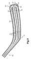
- FIG. 6 is a perspective view of a portion of an inflatable bladder and a pre-preg composite element before the pre-preg composite element has been wrapped around the bladder.
- FIG. 7 is a perspective view of the portion of the inflatable bladder and the pre-preg composite element of FIG. 6 with the pre-preg composite element having been wrapped around the bladder.
- FIG. 8 is a top plan view of a bladder apparatus (with individually wrapped bladders) for use in bladder molding a hockey stick blade being an embodiment of the present invention.
- FIG. 9 is a top plan view of the bladder apparatus of FIG. 8 and an additional pre-preg composite element for collecting wrapping the previously individually bladders of the bladder apparatus.
- FIG. 10 is a top plan view of the bladder apparatus and additional pre-preg composite element of FIG. 9 , with the additional pre-preg composite element having been collectively wrapped around the bladders and with the bladder apparatus having been placed into a mold for curing the pre-preg composite elements.
- FIG. 11 is a top plan view of a cured hockey stick blade structure before removal from the mold.
- FIG. 12 is a top plan view of an inflatable bladder apparatus with bladders having been individually wrapped with pre-preg composite elements and an additional pre-preg composite element for collectively wrapping the previously individually wrapped bladders; the hockey stick blade formed through the use thereof being another embodiment of the present invention.
- FIG. 13 is a top plan view of an inflatable bladder apparatus with bladders having been individually wrapped with pre-preg composite elements and an additional pre-preg composite element for collectively wrapping the previously individually wrapped bladders; the hockey stick blade formed through the use thereof being another embodiment of the present invention.
- FIG. 14 is a top plan view of an inflatable bladder apparatus with bladders having been individually wrapped with pre-preg composite elements and an additional pre-preg composite element for collectively wrapping the previously individually wrapped bladders; the hockey stick blade formed through the use thereof being another embodiment of the present invention.
- FIGS. 1 to 5 there is shown an ice hockey stick blade 100 , being an embodiment of the present invention.
- the blade 100 has an elongated fiber-reinforced polymer body 102 .
- the body 102 of the blade 100 has a fiber-reinforced polymer front face element 104 and a fiber-reinforced polymer rear face element 106 .
- the rear face element 106 is spaced apart from the front face element 104 .
- the blade 100 also has a neck 108 , a heel 110 , and a toe 112 .
- the longitudinal cavities 114 are generally oblong circular shaped or pill-shaped and have curved ends 116 in transverse cross-section. (This shape is created via the bladder molding process described hereinbelow.)
- a plurality (in this embodiment, three) fiber-reinforced polymer structural members 118 interconnect the front face element 104 and the rear face element 106 .
- Each of the structural members 118 is biconcave (i.e., has two concave faces 120 ) in transverse cross-section.
- the longitudinal cavities 114 extend the entire longitudinal length of the blade 100 and extend within the neck 108 of the blade 100 .
- the longitudinal cavities 114 are also connected together in pairs of twos at their toe ends 122 by U-shaped cavities 124 .
- the longitudinal cavities 114 contain ambient pressure air. It can also be seen in FIG. 5 , that the structural members 118 extend longitudinally within the body 102 of the blade.
- the blade 100 is formed via a bladder molding process.
- the bladder molding process requires a bladder molding apparatus 126 .
- two bladder molding apparatuses 126 are used together to form the blade 100 .
- Each bladder molding apparatus 126 has an elongated inflatable bladder 128 with a U-shape 130 at one end thereof and a nozzle 132 at the other end thereof.
- portions of the bladders 128 are wrapped with a pre-preg composite material element (shown prior to wrapping as element 134 in FIG. 6 and after having been wrapped as element 136 in FIGS. 7 and 8 .)
- a pre-preg composite material element shown prior to wrapping as element 134 in FIG. 6 and after having been wrapped as element 136 in FIGS. 7 and 8 .
- the Figures are generally schematic and in most embodiments many (relatively) smaller elements 134 are used to wrap a bladder 128 rather than a large single element.
- the bladder apparatuses 126 are then placed side by side and aligned on an additional pre-preg composite material element 138 .
- the additional pre-preg composite material element 138 is then wrapped collectively around all of the individually wrapped bladders 128 of each of the bladder apparatuses 126 .
- Additional layers of pre-preg composite elements can also be placed about the wrapped bladder apparatuses 126 to provide desired properties of the finished blade. Any of the various techniques known in the art for layering various sized, shaped, and thickness pre-preg materials on a hockey stick blade can be used.
- the resulting double-bladder-apparatus shown as 140 in FIG.
- the criss-cross pattern on the additional pre-preg composite material element 138 is present for ease of viewing to distinguish it from the elements 136 .
- the criss-cross pattern thus does not indicate any particular structure.
- the bladder molding apparatuses 126 are oriented with respect to the additional pre-preg composite material element 138 and the mold 142 in such a way that the bladders extend the complete longitudinal length of the blade 100 to be formed, as well as through the neck 108 of the blade to be formed.
- the nozzles 132 extend out the neck 108 of the blade 100 to be formed.
- the mating portion of the mold (not shown) is then placed on the mold 142 and the bladders 128 are inflated via injection of air through the nozzles 132 .
- the mold 142 is heated to cure the pre-preg composite material into a final fiber-reinforced polymer forming the hockey stick blade (structure) 100 , best seen in FIG. 11 .
- the bladders are deflated and the mold 142 is allowed to cool. In some embodiments, the bladders are at least partially removed from the interior of the (now cured) hockey stick blade 100 . Cavities 114 have been formed in the body 102 of the blade 100 where the bladders 128 were during the curing process.
- the front face element 104 of the blade 100 , the rear face element 106 of the blade 100 and the structural members 118 of the blade 100 are all one single unitary structure.
- the neck 108 of the blade 100 can be attached to the proximal end of a hockey stick shaft (not shown) in a conventional manner.
- FIG. 12 shows a method of fabrication of a hockey blade (final blade not shown) being another embodiment of the invention, via a similar bladder molding process.
- the bladder molding apparatuses 226 are oriented with respect to the additional pre-preg composite material element 238 and with respect to the mold (not shown) in such a way that the bladders 228 extend almost the complete longitudinal length of central portion 244 the blade to be formed, as well as through the neck 108 of the blade to be formed.
- the nozzles 232 extend from the toe end of the blade to be formed, and the U-shaped ends 230 of the bladders 228 are in the neck of the blade to be formed.
- the hockey blade structure has been formed via this method and the bladders 228 have been removed, it will be required to seal the holes left after their removal. This may be done, for example, by adding additional pre-preg material at the toe end of the hockey blade structure, inserting the structure in an appropriate mold and curing the additional pre-preg material.
- the final blade has cavities that extend almost the entire central portion 244 of the blade and through the neck 208 of the blade.
- FIG. 13 shows a method of fabrication of a hockey blade (final blade not shown) being another embodiment of the invention, via a similar bladder molding process as is shown in FIG. 12 .
- the bladder molding apparatuses 326 are oriented with respect to the additional pre-preg composite material element 338 and with respect to the mold (not shown) in such a way that the bladders 328 extend almost the complete longitudinal length of the central portion 344 blade to be formed, but not through the neck 308 of the blade to be formed.
- the U-shaped ends 330 of the bladders 328 remain within the central portion 344 of the blade to be formed.
- the nozzles 332 extend from the toe end of the blade to be formed.
- the final blade has cavities that extend almost the entire central portion 244 of the blade but not through the neck 208 of the blade.
- FIG. 14 shows a method of fabrication of a hockey blade (final blade not shown) being another embodiment of the invention, via a similar bladder molding process as is shown in FIG. 12 .
- the bladder molding apparatuses 426 are oriented with respect to the additional pre-preg composite material element 438 and with respect to the mold (not shown) in such a way that the bladders 428 extend almost the complete longitudinal length of the central portion 444 blade to be formed, but not through the neck 408 of the blade to be formed.
- the U-shaped ends 430 of the bladders 428 remain within the central portion 444 of the blade to be formed, at the toe end. In this embodiment, however, the nozzles 432 extend from the heel end of the blade to be formed.
- the hockey blade structure has been formed via this method and the bladders 428 have been removed, it will be required to seal the holes (albeit in the heel end) left after their removal.
- the final blade has cavities that extend almost the entire central portion 444 of the blade but not through the neck 408 of the blade.
- the cavities contain ambient pressure air in the final hockey stick blade.
Abstract
Description
-
- wrapping at least one inflatable bladder with at least one pre-preg composite element;
- placing at least one wrapped inflatable bladder within a mold having a general form of a hockey stick blade;
- inflating the at least one wrapped inflatable bladder within the mold; and
- heating the mold to cure the at least one pre-preg composite element and form a cured hockey blade structure.
Claims (8)
Priority Applications (2)
| Application Number | Priority Date | Filing Date | Title |
|---|---|---|---|
| US13/341,894 US9044657B2 (en) | 2011-12-30 | 2011-12-30 | Hockey stick blade |
| US14/701,815 US20150231464A1 (en) | 2011-12-30 | 2015-05-01 | Hockey stick blade |
Applications Claiming Priority (1)
| Application Number | Priority Date | Filing Date | Title |
|---|---|---|---|
| US13/341,894 US9044657B2 (en) | 2011-12-30 | 2011-12-30 | Hockey stick blade |
Related Child Applications (1)
| Application Number | Title | Priority Date | Filing Date |
|---|---|---|---|
| US14/701,815 Division US20150231464A1 (en) | 2011-12-30 | 2015-05-01 | Hockey stick blade |
Publications (2)
| Publication Number | Publication Date |
|---|---|
| US20130172135A1 US20130172135A1 (en) | 2013-07-04 |
| US9044657B2 true US9044657B2 (en) | 2015-06-02 |
Family
ID=48695262
Family Applications (2)
| Application Number | Title | Priority Date | Filing Date |
|---|---|---|---|
| US13/341,894 Active 2032-09-08 US9044657B2 (en) | 2011-12-30 | 2011-12-30 | Hockey stick blade |
| US14/701,815 Abandoned US20150231464A1 (en) | 2011-12-30 | 2015-05-01 | Hockey stick blade |
Family Applications After (1)
| Application Number | Title | Priority Date | Filing Date |
|---|---|---|---|
| US14/701,815 Abandoned US20150231464A1 (en) | 2011-12-30 | 2015-05-01 | Hockey stick blade |
Country Status (1)
| Country | Link |
|---|---|
| US (2) | US9044657B2 (en) |
Cited By (4)
| Publication number | Priority date | Publication date | Assignee | Title |
|---|---|---|---|---|
| US20160303445A1 (en) * | 2015-04-15 | 2016-10-20 | True Temper Sports, Inc. | Hockey stick having reinforced core structure |
| US20190290982A1 (en) * | 2014-05-13 | 2019-09-26 | Bauer Hockey, Llc | Sporting Goods Including Microlattice Structures |
| USD883410S1 (en) * | 2018-10-05 | 2020-05-05 | Bauer Hockey, Llc | Hockey blade |
| US20200407894A1 (en) * | 2019-06-28 | 2020-12-31 | The Boeing Company | Pulsed-pressure consolidation of braided preforms for composite parts |
Families Citing this family (9)
| Publication number | Priority date | Publication date | Assignee | Title |
|---|---|---|---|---|
| US9138942B2 (en) * | 2009-11-14 | 2015-09-22 | Expandable Structures, Llc | Composite structure manufacturing method and apparatus |
| US9044658B2 (en) * | 2011-11-04 | 2015-06-02 | Warrior Sports, Inc. | I-beam construction in a hockey blade core |
| US9993707B2 (en) | 2013-07-30 | 2018-06-12 | Bauer Hockey, Llc | Hockey-stick blade with reinforcing frame |
| US9744417B2 (en) * | 2013-07-30 | 2017-08-29 | Bauer Hockey, Llc | Hockey-stick blade with reinforcing frame |
| US9248356B2 (en) | 2013-08-09 | 2016-02-02 | Easton Hockey, Inc. | Hockey-stick blade with tailored performance regions |
| US9320952B2 (en) | 2014-08-08 | 2016-04-26 | Sport Maska Inc. | Two-part hockey stick |
| GB2527862B (en) * | 2014-10-09 | 2016-05-18 | Rockwood Composites Ltd | A Hockey Stick And A Method of Manufacturing Thereof |
| EP3047881B1 (en) * | 2015-01-23 | 2018-07-11 | Bauer Hockey Ltd. | Hockey-stick blade with reinforcing frame |
| US20200222772A1 (en) * | 2017-12-14 | 2020-07-16 | Bauer Hockey, Llc | Hockey Stick and Blade for Hockey Stick |
Citations (22)
| Publication number | Priority date | Publication date | Assignee | Title |
|---|---|---|---|---|
| US3270111A (en) * | 1961-05-03 | 1966-08-30 | Haldemann S A | Method of producing a hollow article |
| US3493240A (en) * | 1967-06-06 | 1970-02-03 | Herbert R Jenks | Laminated fiber glass ski and process for making the same |
| US3641230A (en) * | 1969-01-21 | 1972-02-08 | Dura Fiber | Method for making prestressed laminated fiber glass structures |
| US4488721A (en) * | 1982-05-21 | 1984-12-18 | Franck Donald R | Hockey stick blade with synthetic coating and exposed wear resistant base |
| US4511523A (en) * | 1982-11-16 | 1985-04-16 | Joseph Hsu | Fabrication of a composite material racket frame |
| US4828781A (en) * | 1987-06-26 | 1989-05-09 | Duplessis Delano A | Method of molding composite bicycle frames |
| CA2062635A1 (en) | 1992-03-11 | 1993-09-12 | Kun-Nan Lo | Method for producing an ice hockey stick and the product therefor |
| US5407195A (en) | 1992-10-06 | 1995-04-18 | K.C.G. Hockey Finland Oy | Blade construct for a hockey stick or the like |
| US5417418A (en) * | 1992-12-10 | 1995-05-23 | Prince Manufacturing, Inc. | Monoshaft composite tennis racquet |
| US5624519A (en) * | 1992-05-29 | 1997-04-29 | Trek Bicycle, Corp. | Method making a composite bicycle frame using composite lugs |
| US5848800A (en) * | 1993-06-09 | 1998-12-15 | Kastle Aktiengesellschaft | Ski |
| US5853651A (en) * | 1995-09-07 | 1998-12-29 | Simula, Inc. | High pressure hollow process for manufacturing composite structures |
| US5935029A (en) | 1997-06-24 | 1999-08-10 | Oddzon, Inc. | Sound-producing hockey stick |
| US20030004019A1 (en) | 2001-07-02 | 2003-01-02 | 2946-6380 Quebec Inc. C/O Production P.H. Enr | Blade core for hockey stick and the like |
| US20030119612A1 (en) * | 2000-09-15 | 2003-06-26 | Jas Easton | Hockey stick |
| US6824636B2 (en) * | 1997-04-23 | 2004-11-30 | Radius Engineering, Inc. | Method of manufacturing a composite golf club head |
| US20050181897A1 (en) | 2004-02-17 | 2005-08-18 | Davis Chen | Blade member |
| US20050258575A1 (en) * | 2001-03-13 | 2005-11-24 | Christian Kruse | Non-isothermal method for fabricating hollow composite parts |
| WO2006042422A1 (en) | 2004-10-21 | 2006-04-27 | 2946-6380 Quebec Inc. | Hockey stick blade and a method of making thereof |
| US7150692B2 (en) | 2004-11-01 | 2006-12-19 | Arthur Hong | Sport good of composite material with lighter weight and greater rigidity |
| US20100035708A1 (en) | 2008-08-06 | 2010-02-11 | Easton Sports, Inc. | Hockey stick |
| US7963868B2 (en) | 2000-09-15 | 2011-06-21 | Easton Sports, Inc. | Hockey stick |
Family Cites Families (5)
| Publication number | Priority date | Publication date | Assignee | Title |
|---|---|---|---|---|
| US20040084815A1 (en) * | 2002-11-05 | 2004-05-06 | Ray Blotteaux | One-piece shaft construction and a method of construction using bladder molding |
| US20050070382A1 (en) * | 2003-09-29 | 2005-03-31 | Loschiavo Mark A. | Device and method for adding weight to a hockey stick blade |
| US6918847B2 (en) * | 2003-10-24 | 2005-07-19 | Bauer Nike Hockey Inc. | Hockey stick blade |
| US7258625B2 (en) * | 2004-09-08 | 2007-08-21 | Nike, Inc. | Golf clubs and golf club heads |
| US9044658B2 (en) * | 2011-11-04 | 2015-06-02 | Warrior Sports, Inc. | I-beam construction in a hockey blade core |
-
2011
- 2011-12-30 US US13/341,894 patent/US9044657B2/en active Active
-
2015
- 2015-05-01 US US14/701,815 patent/US20150231464A1/en not_active Abandoned
Patent Citations (27)
| Publication number | Priority date | Publication date | Assignee | Title |
|---|---|---|---|---|
| US3270111A (en) * | 1961-05-03 | 1966-08-30 | Haldemann S A | Method of producing a hollow article |
| US3493240A (en) * | 1967-06-06 | 1970-02-03 | Herbert R Jenks | Laminated fiber glass ski and process for making the same |
| US3641230A (en) * | 1969-01-21 | 1972-02-08 | Dura Fiber | Method for making prestressed laminated fiber glass structures |
| US4488721A (en) * | 1982-05-21 | 1984-12-18 | Franck Donald R | Hockey stick blade with synthetic coating and exposed wear resistant base |
| US4511523A (en) * | 1982-11-16 | 1985-04-16 | Joseph Hsu | Fabrication of a composite material racket frame |
| US4828781A (en) * | 1987-06-26 | 1989-05-09 | Duplessis Delano A | Method of molding composite bicycle frames |
| CA2062635A1 (en) | 1992-03-11 | 1993-09-12 | Kun-Nan Lo | Method for producing an ice hockey stick and the product therefor |
| US5624519A (en) * | 1992-05-29 | 1997-04-29 | Trek Bicycle, Corp. | Method making a composite bicycle frame using composite lugs |
| US5407195A (en) | 1992-10-06 | 1995-04-18 | K.C.G. Hockey Finland Oy | Blade construct for a hockey stick or the like |
| US5417418A (en) * | 1992-12-10 | 1995-05-23 | Prince Manufacturing, Inc. | Monoshaft composite tennis racquet |
| US5848800A (en) * | 1993-06-09 | 1998-12-15 | Kastle Aktiengesellschaft | Ski |
| US5853651A (en) * | 1995-09-07 | 1998-12-29 | Simula, Inc. | High pressure hollow process for manufacturing composite structures |
| US6824636B2 (en) * | 1997-04-23 | 2004-11-30 | Radius Engineering, Inc. | Method of manufacturing a composite golf club head |
| US5935029A (en) | 1997-06-24 | 1999-08-10 | Oddzon, Inc. | Sound-producing hockey stick |
| US7963868B2 (en) | 2000-09-15 | 2011-06-21 | Easton Sports, Inc. | Hockey stick |
| US20030119612A1 (en) * | 2000-09-15 | 2003-06-26 | Jas Easton | Hockey stick |
| US20050258575A1 (en) * | 2001-03-13 | 2005-11-24 | Christian Kruse | Non-isothermal method for fabricating hollow composite parts |
| US20030004019A1 (en) | 2001-07-02 | 2003-01-02 | 2946-6380 Quebec Inc. C/O Production P.H. Enr | Blade core for hockey stick and the like |
| US20050181897A1 (en) | 2004-02-17 | 2005-08-18 | Davis Chen | Blade member |
| WO2006042422A1 (en) | 2004-10-21 | 2006-04-27 | 2946-6380 Quebec Inc. | Hockey stick blade and a method of making thereof |
| US20060089215A1 (en) | 2004-10-21 | 2006-04-27 | 2946-6380 Quebec Inc. | Hockey stick blade and a method of making thereof |
| US7326136B2 (en) | 2004-10-21 | 2008-02-05 | 2946-6380 Quebec Inc. | Hockey stick blade and a method of making thereof |
| US7150692B2 (en) | 2004-11-01 | 2006-12-19 | Arthur Hong | Sport good of composite material with lighter weight and greater rigidity |
| WO2010017421A1 (en) | 2008-08-06 | 2010-02-11 | Easton Sports, Inc. | Hockey stick |
| US7914403B2 (en) | 2008-08-06 | 2011-03-29 | Easton Sports, Inc. | Hockey stick |
| US20100035708A1 (en) | 2008-08-06 | 2010-02-11 | Easton Sports, Inc. | Hockey stick |
| US20110160009A1 (en) | 2008-08-06 | 2011-06-30 | Easton Sports, Inc. | Hockey stick |
Cited By (8)
| Publication number | Priority date | Publication date | Assignee | Title |
|---|---|---|---|---|
| US20190290982A1 (en) * | 2014-05-13 | 2019-09-26 | Bauer Hockey, Llc | Sporting Goods Including Microlattice Structures |
| US11779821B2 (en) * | 2014-05-13 | 2023-10-10 | Bauer Hockey Llc | Sporting goods including microlattice structures |
| US11794084B2 (en) | 2014-05-13 | 2023-10-24 | Bauer Hockey Llc | Sporting goods including microlattice structures |
| US11844986B2 (en) | 2014-05-13 | 2023-12-19 | Bauer Hockey Llc | Sporting goods including microlattice structures |
| US20160303445A1 (en) * | 2015-04-15 | 2016-10-20 | True Temper Sports, Inc. | Hockey stick having reinforced core structure |
| USD883410S1 (en) * | 2018-10-05 | 2020-05-05 | Bauer Hockey, Llc | Hockey blade |
| US20200407894A1 (en) * | 2019-06-28 | 2020-12-31 | The Boeing Company | Pulsed-pressure consolidation of braided preforms for composite parts |
| US11572644B2 (en) * | 2019-06-28 | 2023-02-07 | The Boeing Company | Pulsed-pressure consolidation of braided preforms for composite parts |
Also Published As
| Publication number | Publication date |
|---|---|
| US20150231464A1 (en) | 2015-08-20 |
| US20130172135A1 (en) | 2013-07-04 |
Similar Documents
| Publication | Publication Date | Title |
|---|---|---|
| US9044657B2 (en) | Hockey stick blade | |
| US6761653B1 (en) | Composite wrap bat with alternative designs | |
| RU2403940C2 (en) | Construction of hockey stick with multiple tubular structure | |
| US6939257B2 (en) | Method for manufacturing shaft of stick, and shaft | |
| RU2401688C2 (en) | Hockey stick from one hollow initial tube | |
| US20180353820A1 (en) | Hockey-Stick Blade with Reinforcing Frame | |
| US20050277494A1 (en) | Lacrosse stick having a composite shaft | |
| EP2837410B1 (en) | Hockey-stick blade with reinforcing frame | |
| WO2009076439A1 (en) | Split core hockey stick blade | |
| GB2496583A (en) | A hockey stick with three coextensive hollow sections | |
| US20090149284A1 (en) | Hockey Stick Blade Having Fiber-Reinforced High Density Foam Core | |
| US20080261733A1 (en) | Composite racquet and method of making same | |
| CA2762872C (en) | Hockey stick blade | |
| US20050043123A1 (en) | Lacrosse stick | |
| EP3105041B1 (en) | Method of manufacturing an elongated article, elongated article, obtainable by the method | |
| EP3238923A1 (en) | Sports racket with core-embedded struts and method for producing | |
| WO2012149490A1 (en) | Improved composite member and method of making | |
| CN114765962A (en) | Shaft for sporting activities | |
| EP2628509A1 (en) | Floor ball stick | |
| WO2008129361A2 (en) | Hockey stick system having a multiple tube structure with an insert | |
| EP2133125B1 (en) | Shaft for a sport stick | |
| EP3047881B1 (en) | Hockey-stick blade with reinforcing frame | |
| US20210277547A1 (en) | Methods of asymmetrically weaving raw fiber materials to create fiber reinforced products and products created thereby | |
| GB2533766A (en) | Stick for hitting a sporting item | |
| US20060199680A1 (en) | Ball game racquet, especially tennis racquet |
Legal Events
| Date | Code | Title | Description |
|---|---|---|---|
| AS | Assignment |
Owner name: SPORT MASKA INC., QUEBEC Free format text: ASSIGNMENT OF ASSIGNORS INTEREST;ASSIGNOR:JEANNEAU, PHILIPPE;REEL/FRAME:027611/0489 Effective date: 20120117 |
|
| STCF | Information on status: patent grant |
Free format text: PATENTED CASE |
|
| AS | Assignment |
Owner name: CANADIAN IMPERIAL BANK OF COMMERCE, CANADA Free format text: SECURITY INTEREST;ASSIGNOR:SPORT MASKA INC.;REEL/FRAME:044050/0799 Effective date: 20170927 |
|
| MAFP | Maintenance fee payment |
Free format text: PAYMENT OF MAINTENANCE FEE, 4TH YEAR, LARGE ENTITY (ORIGINAL EVENT CODE: M1551); ENTITY STATUS OF PATENT OWNER: LARGE ENTITY Year of fee payment: 4 |
|
| AS | Assignment |
Owner name: CANADIAN IMPERIAL BANK OF COMMERCE, AS AGENT AND GRANTEE, CANADA Free format text: SECURITY INTEREST;ASSIGNOR:SPORT MASKA INC.;REEL/FRAME:058597/0573 Effective date: 20211223 |
|
| MAFP | Maintenance fee payment |
Free format text: PAYMENT OF MAINTENANCE FEE, 8TH YEAR, LARGE ENTITY (ORIGINAL EVENT CODE: M1552); ENTITY STATUS OF PATENT OWNER: LARGE ENTITY Year of fee payment: 8 |
|
| AS | Assignment |
Owner name: CANADIAN IMPERIAL BANK OF COMMERCE, AS AGENT AND GRANTEE, CANADA Free format text: SECURITY INTEREST;ASSIGNOR:SPORT MASKA INC.;REEL/FRAME:063623/0161 Effective date: 20230406 |