US7679864B2 - Narrow width actuator for tape drive systems - Google Patents
Narrow width actuator for tape drive systems Download PDFInfo
- Publication number
- US7679864B2 US7679864B2 US11/506,968 US50696806A US7679864B2 US 7679864 B2 US7679864 B2 US 7679864B2 US 50696806 A US50696806 A US 50696806A US 7679864 B2 US7679864 B2 US 7679864B2
- Authority
- US
- United States
- Prior art keywords
- actuator
- assembly
- laterally extending
- head carriage
- carriage assembly
- Prior art date
- Legal status (The legal status is an assumption and is not a legal conclusion. Google has not performed a legal analysis and makes no representation as to the accuracy of the status listed.)
- Expired - Fee Related, expires
Links
Images


Classifications
-
- G—PHYSICS
- G11—INFORMATION STORAGE
- G11B—INFORMATION STORAGE BASED ON RELATIVE MOVEMENT BETWEEN RECORD CARRIER AND TRANSDUCER
- G11B5/00—Recording by magnetisation or demagnetisation of a record carrier; Reproducing by magnetic means; Record carriers therefor
- G11B5/48—Disposition or mounting of heads or head supports relative to record carriers ; arrangements of heads, e.g. for scanning the record carrier to increase the relative speed
- G11B5/58—Disposition or mounting of heads or head supports relative to record carriers ; arrangements of heads, e.g. for scanning the record carrier to increase the relative speed with provision for moving the head for the purpose of maintaining alignment of the head relative to the record carrier during transducing operation, e.g. to compensate for surface irregularities of the latter or for track following
- G11B5/584—Disposition or mounting of heads or head supports relative to record carriers ; arrangements of heads, e.g. for scanning the record carrier to increase the relative speed with provision for moving the head for the purpose of maintaining alignment of the head relative to the record carrier during transducing operation, e.g. to compensate for surface irregularities of the latter or for track following for track following on tapes
Definitions
- LTO Linear Tape-Open
- DLT Digital Linear Tape
- the claimed embodiments are directed to high bandwidth actuators.
- Some of the issues with high performance actuators are: minimizing moving mass, optimization of the working lateral range of motion and controlling the high order unwanted resonance frequencies above a minimum frequency that is determined based on the tracking servo bandwidth requirements.
- drive form factors for example LTO form factor requirements
- installation/mounting requirements are also a concern.
- Some computer industry requirements include the drive mounting configurations. For example, some computer manufactures specify a drive-mounting configuration requirement that the drive can be mounted on its lateral side or on its bottom side. The side-mounting configuration requires two sets of hole-patterns with a minimum screw length that will support the drive in a computer chassis. A typical screw length requirement is about 4 to 5 millimeters.
- the pin threading mechanisms In a LTO half-high drive (1 ⁇ 2 of the standard height of 31 ⁇ 4 inches) the pin threading mechanisms must be spaced away from the mounting screw. Thus, the actuator must fit between the pin threading mechanisms and the drive reel located in the back. The actuator must also fit in the limited space in the width dimension.
- Prior art actuator assemblies are typically not suitable for tape drives with smaller form factors where drive components are more tightly packed.
- some of the actuator configurations of the prior art force a lower 1st mode resonance frequency response at around 100 Hz.
- a lower 1st mode of the spring-mass system also results in a lower 2nd mode of resonance.
- One embodiment by way of non-limiting example provides for a servo-controlled, head actuator design that has low profile characteristics in both the height and width dimensions.
- the low height allows the actuator to fit into a half-high tape drive form factor.
- the construction of the actuator reduces the width of the tape drive system, and allows the industry standard mounting with the necessary screw length.
- the actuator comprises a smaller, concentrated moving mass coupled with a flexure construction having a narrowed width with added ribs for torsional stiffness.
- the actuator design includes a coarse actuator assembly for larger movements of the head, and a fine grain actuator, including a voice coil motor, responsive to analysis of servo signals.
- a fine grain actuator including a voice coil motor, responsive to analysis of servo signals.
- the voice coil motor of the fine actuator and the coarse actuator shafts are in line. Since the centerlines of the shafts are in-line with the voice coil motor, the resonance response of the shaft spring-mass system is reduced.
- FIG. 1 illustrates a typical LTO tape cartridge
- FIG. 2 illustrates a typical LTO tape drive housing with the cartridge of FIG. 1 inserted
- FIG. 3 is a top-down view of the cartridge inserted into the tape drive which includes a head actuator assembly of the claimed embodiments;
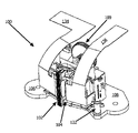
- FIG. 4 is a perspective view of an actuator assembly, in accordance with an exemplary embodiment
- FIG. 5 is an alternative perspective view of the actuator assembly, in accordance with an exemplary embodiment
- FIG. 6 is a perspective view detailing a magnetic head and fine-grain actuator assembly, in accordance with an exemplary embodiment
- FIG. 7 is an exploded view illustrating various components of the actuator assembly, in accordance with an exemplary embodiment
- FIGS. 8A and 8B are exploded views illustrating some of the components of the fine actuator, in accordance with an exemplary embodiment.
- FIG. 9 is a top-down block diagram view illustrating flexible circuit orientation in relation to a tape travel path, in accordance with an exemplary embodiment.
- FIG. 1 illustrates a typical LTO tape cartridge 10
- FIG. 2 illustrates a typical LTO tape drive housing 200 with the cartridge 10 of FIG. 1 inserted.
- Cartridge 10 is inserted into drive 200 in a direction specified by arrow 12 .
- Cartridge 10 also includes grip lines 14 for easy handling.
- cartridge 10 includes various lock depressions 18 (also repeated on the opposite side) that mate with a male counterpart, in drive 200 , to ensure a snug fit after cartridge 10 is inserted into drive 200 .
- Drive 200 includes an eject button 202 and various indicators 204 .
- the drive 200 may be designed to fit into a 5.25 inch form factor for installation into a bay of a desktop or server box. Of course, other implementations are possible.
- the drive 200 may be a stand-alone unit, such as a desktop drive that is external from a host computing system.
- FIG. 3 is a top-down view of the cartridge 10 inserted into the tape drive 200 which includes a head actuator assembly of the claimed embodiments.
- a full description of the various components of drive 200 is intentionally not included in order to not unnecessarily obscure the claimed embodiments.
- some of the major components include a take-up hub 300 , various tape-threading roller guides ( 302 , 306 ), magnetic head 102 and flex cables ( 134 , 136 ).
- Drive 200 will also typically contain one or more processors, a memory and a controller. Area 500 will be referred to later.
- FIGS. 4 and 5 show a head actuator assembly 100 comprising a magnetic head 102 , and a head carriage 104 .
- the magnetic head 102 is preferably retained in a forked shaped portion 103 (see FIGS. 8A and 9 ) of the head carriage 104 preferably by an adhesive.
- Other types of fasteners may be used to fasten the magnetic head 102 to the head carriage 104 such as an interference fit or mechanical fasteners such as screws, for example.
- the actuator assembly 100 illustrated in FIGS. 4 and 5 , further includes a coarse actuator and a fine actuator.
- the head carriage 104 is operably attached to the fine actuator, while the fine actuator is attached to the coarse actuator.
- the coarse actuator comprises an actuator base 106 (to which the head carriage 104 and fine actuator are attached).
- the coarse actuator in one implementation, includes a drive assembly 109 that displaces the coarse actuator base 106 along shafts 107 that protrude from base plate assembly 108 .
- the second shaft 107 is located on an opposite side of magnetic head 102 .
- the coarse actuator translates the entire fine actuator assembly across the tape for a travel distance of about 9 mm to, for example, move magnetic head 102 between tracks.
- Magnetic head 102 may include one to several bumps and each bump will usually include a plurality of read and write elements.
- fine actuator and “moving mass” can be used interchangeably and generally refer to the following collection of parts: coarse actuator base 106 , head carriage 104 , magnetic head 102 , voice coil motor 160 and top and bottom flexure springs ( 140 , 142 /refer to FIGS. 7-8B ). Additionally, the phrase “coarse actuator” generally refers to the following collection of parts: base plate assembly 108 , shafts 107 , drive assembly 109 and the coarse actuator base 106 .
- the fine actuator controls the head carriage assembly 102 / 104 , relative to coarse actuator base 106 , using a voice coil motor (VCM) assembly (see FIGS. 8A & 8B ).
- the voice coil motor assembly includes a voice coil portion 160 and magnetic housing assembly 162 .
- the voice coil portion 160 is attached to the head carriage 104 to translate with the head carriage 104 , while the outer portion 162 is attached to the coarse actuator base 106 .
- the VCM of the fine actuator is a flat voice coil motor.
- the voice coil portion 160 is suspended in a magnetic field produced by one or more magnets in the magnetic housing assembly 162 of the voice coil motor.
- the fine actuator moves magnetic head 102 based on analysis of the servo signals, contained on a tape, to keep the magnetic head 102 in substantial alignment with a selected track.
- the voice coil motor assembly and associated magnets located in the magnetic housing assembly 162 are oriented relative to the direction of travel of the coarse actuator base 106 . This configuration also contributes to a reduced actuator assembly 100 size.
- the fine actuator functions under closed loop servo control, while the coarse actuator utilizes open loop control.
- the trigger point of the reference hall sensor magnet assembly 122 provides a known location for the head with respect to tape.
- the linear hall sensor magnet 124 (see FIG. 5 ) along with the reference hall sensor magnet assembly 122 provides the translation information of the fine actuator. In one implementation, this information is used to provide the damping of the first mode resonance of the spring-mass system of the fine actuator.
- the magnetic head 102 traverses across a tape width to seek a relevant track.
- incidents may include booting up the tape drive 200 , tape-loading sequence, etc.
- the reference hall-sensor magnet assembly 122 and reference hall sensor 800 are utilized.
- the reference hall magnet assembly 122 is secured to the actuator base plate 108 and the reference hall sensor 800 is secured to the coarse base actuator 106 .
- the actuator base plate 108 is stationary to the drive 200 .
- the reference hall sensor 800 arrives in the vicinity of the reference hall magnet assembly 122 , the reference hall sensor 800 is triggered. This information is utilized to locate the magnetic head 102 with respect to the tape.
- the fine actuator of the head actuator assembly 100 is utilized to keep the head on a track under a servo control.
- the dual pole magnet 125 is only partly visible in FIG. 5 . Any movements in the tape or head carriage 104 can create a misalignment between a read/write element of the magnetic head 102 and a corresponding track on the tape.
- the linear hall sensor 124 is attached to the flex cable 134 which is attached to the head carriage 104 .
- the corresponding dual pole magnet 125 is attached to the coarse actuator base 106 . When the head carriage 104 moves, the linear hall sensor 124 will also move with respect to the dual pole magnet 125 .
- the dual pole magnet 125 has two poles—north and south.
- the linear hall sensor 124 When the linear hall sensor 124 is aligned to a null line of the dual pole magnet, there is no signal.
- the linear hall sensor 124 produces the signal which is proportional to the head-translation. The same is true when the magnetic head 102 moves in the negative direction.
- the linear hall sensor 122 provides the signal which is proportional to the head translation.
- This information can be used in number of ways. Some examples include 1) damping of the servo loop and 2) when tape is at the end and it reverses the direction to move from forward to reverse, there is no servo information from the tape.
- the linear hall sensor 124 provides the head location information during this phase.
- flex cables ( 134 , 136 ) are each attached to one of a pair of laterally extending arms ( 104 a , 104 b ) of head carriage 104 .
- the flex cables ( 134 , 136 ) are attached to the laterally extending arms ( 104 a , 104 b ) via an adhesive.
- Flex cables 134 and 136 provide the electrical connection between the magnetic head 102 and a printed circuit board (not shown).
- the head flex circuit portion 132 also connects to the voice coil 160 via pad 178 .
- the screws 176 going through clamp 174 provide the force between the pads of the voice coil flex cable portion 132 and the VCM 160 for electrical continuity. This eliminates any need to provide additional wires between the voice coil and the main PCB (not shown).
- the voice coil 160 terminates at the main PCB via the traces in the flex cable 134 .
- Top flexure spring 140 further includes holes 180 that are utilized to secure top flexure spring 140 to the coarse actuator base 106 via additional screws (not shown). In one implementation, clamps may also be included with the screws. It should be noted that FIG. 7 is an exploded view of various parts. As such, top flexure spring 140 is shown on one side of flex cables 134 and 136 for clarity. FIGS. 8A and 8B correctly characterize the placement of top flexure spring 140 in relation to flex cables 134 and 136 .
- top flexure spring 140 As the head carriage 104 is secured to top flexure spring 140 via screws 176 and the top flexure is further secured to the coarse actuator base 106 via screws (not shown), it can be seen that head carriage 104 is mounted between opposing arms ( 106 a , 106 b ) in area 103 of the coarse actuator base 106 . Head carriage 104 is also coupled to the actuator base 106 via a bottom flexure spring 142 . Similar to top flexure spring 140 , bottom flexure spring 142 is coupled with the head carriage 104 at an inner set of holes 184 via a clamp 186 and screws 188 (note only one screw 188 is intentionally included in FIG. 8A for clarity of the view). Bottom flexure spring 142 is further coupled to the coarse actuator base at holes 190 via clamps 192 and screws (not shown).
- Actuator assembly 100 has two separate resonance frequency vibration modes referred to as the first mode and the second mode.
- the first mode refers to up and down frequency vibrations of the actuator assembly and is generally low frequency.
- the second mode refers to torsional frequency vibration of the moving mass and is generally preferred to be kept as high as possible and preferably five to eight times higher than the closed-loop bandwidth frequency.
- Top and bottom flexures springs 140 and 142 each further include various ribs 194 that are oriented perpendicular to each flexure.
- the top and bottom flexure springs 140 and 142 are metal springs that apply opposing forces to bias the head carriage 104 towards a center position relative to the fine actuator thus providing a resonance frequency dampening effect.
- flexure springs are 140 and 142 are made from 300 series stainless steel.
- the ribs 194 allow for reductions in the width of top and bottom flexure springs 140 and 142 while maintaining desired spring forces. This is accomplished because ribs 194 add torsional stiffness to the top and bottom flexure springs 140 and 142 .
- the overall size of the actuator assembly 100 can be reduced accordingly to fit into a smaller drive enclosure.
- the placement of the top and bottom flexure springs 140 and 142 help to contribute the high second mode of vibration.
- the top and bottom flexure springs 140 and 142 are mounted to be substantially aligned with the center of gravity of the moving mass corresponding to the fine actuator. This can be seen, for example, via FIGS.
- top and bottom flexure springs 140 and 142 are arranged at the top and bottom of head carriage 104 such they coincide at a lateral midpoint of head carriage 104 wherein the lateral midpoint divides head carriage 104 into front and back parts. It should also be noted that since the top and bottom flexure springs 140 and 142 are inline with the moving mass, the ribs 194 are also in-line with the moving mass. As a result, the ribs therefore also help to contribute to a higher second resonance mode.
- the voice coil motor 160 is electrically coupled with a corresponding magnetic circuit that generates a force required to move the magnetic head 102 such that it stays aligned with a particular track on a tape.
- a magnetic moment caused by the force can also excite the shafts 107 and their associated spring-mass system. Since the voice coil 160 is in-line with the shafts 107 , the residual force of the moment arm is substantially zero and the resonance of the shaft's spring-mass system is also reduced substantially.
- FIG. 9 is a top-down block diagram view 900 illustrating flexible circuit orientation in relation to a tape travel path.
- top-down view 900 Included in top-down view 900 are the flex cables 134 and 136 , a portion of the head carriage 104 , magnet head 102 , tape/tape travel path 902 and prior art flex cable orientations 904 .
- the flex cable portions ( 134 a , 136 a /also refer to FIG. 6 ) of the flex cables ( 134 , 136 ) are parallel to the tape/tape travel path 902 .
- the laterally extending arms ( 104 a , 104 b ) extending of the head carriage 104 are oriented substantially parallel to the tape path in the opposing regions proximal to magnetic head 102 .
- This configuration allows the physical distance between the flex cables 134 and 136 , as they extend from the flex cable portions 134 a & 136 a , to be increased. This increased separation reduces the effects of interference or noise associated with a read signal traversing flex cable 136 caused by, for example, write signals traversing flex cable 134 . If the flex cables ( 134 , 136 ) were not oriented parallel to the tape/tape travel path 902 , the distance between the flex cables ( 134 , 136 ) would decrease as can be seen via prior-art flex cable orientations 904 . Furthermore, prior art flex cable orientations 904 are additionally limited in that there is very little room to further separate the two orientations 904 from each other.
- laterally extending arms ( 104 a , 104 b ) form approximately 10 degree angles at either side of fork-shaped portion 103 as indicated by areas 906 and 908 . Since the flex cables ( 134 , 136 ) are attached to the laterally extending arms ( 104 a , 104 b ), flex cable portions 134 a and 136 a (refer to FIG. 6 ) therefore also are oriented about 10 degrees inward in relation to the magnetic head 102 .
- the claimed embodiments provide for a reduced fingerprint actuator assembly capable of fitting into next generation LTO tape drives. Additionally, a higher second mode vibration is achieved by placing flexures with ribs inline with the moving mass/fine actuator. Furthermore, the reduced footprint actuator assembly provides the required extra room in a tape drive housing for tape grabber mechanics as well as providing the option to install the housing in various orientations due to multiple sets of mounting holes for screws. More specifically, area 500 of drive 200 (refer to FIG. 3 ) is freed up to allow for additional mounting screw holes.
- a flat voice coil motor design is employed by the claimed embodiments.
- Prior art voice coils are typically circular. Using a circular voice coil results in an increased fine actuator moving mass. That increase in mass necessitates the use of wider flexures. In turn, wider flexures results in an enhanced width for the actuator as a whole.
- a flat voice coil By using a flat voice coil, those prior art issues are avoided. Additionally, the flat voice coil contributes to the moving mass being concentrated in a small area which in turn helps to achieve the in-line/center of gravity aspects of the claimed embodiments.
Abstract
Description
Claims (16)
Priority Applications (1)
| Application Number | Priority Date | Filing Date | Title |
|---|---|---|---|
| US11/506,968 US7679864B2 (en) | 2006-06-08 | 2006-08-17 | Narrow width actuator for tape drive systems |
Applications Claiming Priority (2)
| Application Number | Priority Date | Filing Date | Title |
|---|---|---|---|
| US80422306P | 2006-06-08 | 2006-06-08 | |
| US11/506,968 US7679864B2 (en) | 2006-06-08 | 2006-08-17 | Narrow width actuator for tape drive systems |
Publications (2)
| Publication Number | Publication Date |
|---|---|
| US20070285845A1 US20070285845A1 (en) | 2007-12-13 |
| US7679864B2 true US7679864B2 (en) | 2010-03-16 |
Family
ID=38821692
Family Applications (1)
| Application Number | Title | Priority Date | Filing Date |
|---|---|---|---|
| US11/506,968 Expired - Fee Related US7679864B2 (en) | 2006-06-08 | 2006-08-17 | Narrow width actuator for tape drive systems |
Country Status (1)
| Country | Link |
|---|---|
| US (1) | US7679864B2 (en) |
Cited By (4)
| Publication number | Priority date | Publication date | Assignee | Title |
|---|---|---|---|---|
| US20100309579A1 (en) * | 2009-06-08 | 2010-12-09 | Quantum Corporation | Dual stage head actuator assembly for tape drive |
| US20120243124A1 (en) * | 2011-03-24 | 2012-09-27 | Fasen Donald J | Actuator with non-moving mass |
| US20170092312A1 (en) * | 2015-09-24 | 2017-03-30 | International Business Machines Corporation | Planar mono coil for two stage head actuator |
| US11295769B2 (en) | 2020-06-29 | 2022-04-05 | Western Digital Technologies, Inc. | Soft mount voice coil motor assembly |
Families Citing this family (4)
| Publication number | Priority date | Publication date | Assignee | Title |
|---|---|---|---|---|
| US20070285844A1 (en) * | 2006-06-08 | 2007-12-13 | Quantum Corporation, A Delaware Corporation | Multi-function head flex-circuit design for tape drives |
| NL2003139A1 (en) * | 2008-07-31 | 2010-02-02 | Asml Holding Nv | Cooling or actuator coils. |
| US8004789B2 (en) | 2009-12-03 | 2011-08-23 | International Business Machines Corporation | Detection and acquisition of a servo pattern subject to lateral motion |
| US11373677B2 (en) | 2020-06-29 | 2022-06-28 | Western Digital Technologies, Inc. | Double bend VCM yoke structure |
Citations (16)
| Publication number | Priority date | Publication date | Assignee | Title |
|---|---|---|---|---|
| US5371636A (en) * | 1990-03-30 | 1994-12-06 | Archive Corporation | Mechanisms for a closed loop head positioner for streaming tape drives |
| US5377052A (en) * | 1993-06-14 | 1994-12-27 | International Business Machines Corporation | Actuator assembly for servo-controlled magnetic tape head |
| US5566039A (en) * | 1994-10-26 | 1996-10-15 | Storage Technology Corporation | Read/write head positioning device |
| US5793573A (en) * | 1995-06-07 | 1998-08-11 | International Business Machines Corporation | Hybrid actuator servo actuated tape drive having a pivotally mounted motion transmission member |
| US5936804A (en) * | 1997-11-26 | 1999-08-10 | Quantum Corporation | Impact features on suspensions for improved damage resiliancy in disk drives |
| US6075678A (en) | 1998-03-24 | 2000-06-13 | Quantum Corporation | Pivoting lever cam guide tape head positioner |
| US20020041470A1 (en) * | 1998-09-22 | 2002-04-11 | Seagate Technology Llc | Flexible circuit routing configuration for a fine/coarse positioner for a tape drive |
| US20020060884A1 (en) * | 2000-10-25 | 2002-05-23 | Mitsumi Electric Co. Ltd. | Actuator assembly |
| US6411474B1 (en) | 1998-06-22 | 2002-06-25 | Hewlett-Packard Co. | Carriage and actuator assembly |
| US6594118B1 (en) | 2000-02-03 | 2003-07-15 | Seagate Removable Storage Solutions Llc | Suspension system for a head-carriage assembly for a magnetic tape drive |
| US6697229B2 (en) | 2001-10-02 | 2004-02-24 | Mitsumi Electric Co., Ltd. | Head transfer actuator assembly used in a tape device with a head assembly given a bias in a radial direction of the lead screw |
| US6765759B2 (en) | 1999-08-31 | 2004-07-20 | Seagate Technology Llc | Resonance four piece suspension |
| US20040184195A1 (en) * | 2003-01-30 | 2004-09-23 | Certance Llc | Head actuator assembly for a tape drive |
| US7123450B1 (en) * | 2003-11-18 | 2006-10-17 | Storage Technology Corporation | Transducer positioning device utilizing a guide member mounted with flexible members |
| US7359259B2 (en) * | 2004-11-19 | 2008-04-15 | Infineon Technologies Ag | Method for transmission and reception of a data signal on a line pair, as well as a transmission and reception circuit for this purpose |
| US7474495B2 (en) * | 2007-02-20 | 2009-01-06 | Quantum Corporation | Piezoelectric micro-actuator for magnetic tape read/write head |
-
2006
- 2006-08-17 US US11/506,968 patent/US7679864B2/en not_active Expired - Fee Related
Patent Citations (21)
| Publication number | Priority date | Publication date | Assignee | Title |
|---|---|---|---|---|
| US5371636A (en) * | 1990-03-30 | 1994-12-06 | Archive Corporation | Mechanisms for a closed loop head positioner for streaming tape drives |
| US5377052A (en) * | 1993-06-14 | 1994-12-27 | International Business Machines Corporation | Actuator assembly for servo-controlled magnetic tape head |
| US5566039A (en) * | 1994-10-26 | 1996-10-15 | Storage Technology Corporation | Read/write head positioning device |
| US5793573A (en) * | 1995-06-07 | 1998-08-11 | International Business Machines Corporation | Hybrid actuator servo actuated tape drive having a pivotally mounted motion transmission member |
| US5949619A (en) * | 1995-06-07 | 1999-09-07 | International Business Machines Corporation | Servo actuated read/write head actuator assembly for a tape drive |
| US5936804A (en) * | 1997-11-26 | 1999-08-10 | Quantum Corporation | Impact features on suspensions for improved damage resiliancy in disk drives |
| US6075678A (en) | 1998-03-24 | 2000-06-13 | Quantum Corporation | Pivoting lever cam guide tape head positioner |
| US6411474B1 (en) | 1998-06-22 | 2002-06-25 | Hewlett-Packard Co. | Carriage and actuator assembly |
| US6404598B1 (en) | 1998-09-22 | 2002-06-11 | Seagate Technology Llc | Flexible circuit routing configuration for a fine/coarse positioner for a tape drive |
| US20020041470A1 (en) * | 1998-09-22 | 2002-04-11 | Seagate Technology Llc | Flexible circuit routing configuration for a fine/coarse positioner for a tape drive |
| US6765759B2 (en) | 1999-08-31 | 2004-07-20 | Seagate Technology Llc | Resonance four piece suspension |
| US6594118B1 (en) | 2000-02-03 | 2003-07-15 | Seagate Removable Storage Solutions Llc | Suspension system for a head-carriage assembly for a magnetic tape drive |
| US6704169B2 (en) * | 2000-10-25 | 2004-03-09 | Mitsumi Electric Co., Ltd. | Actuator assembly |
| US20020060884A1 (en) * | 2000-10-25 | 2002-05-23 | Mitsumi Electric Co. Ltd. | Actuator assembly |
| US6697229B2 (en) | 2001-10-02 | 2004-02-24 | Mitsumi Electric Co., Ltd. | Head transfer actuator assembly used in a tape device with a head assembly given a bias in a radial direction of the lead screw |
| US20040184195A1 (en) * | 2003-01-30 | 2004-09-23 | Certance Llc | Head actuator assembly for a tape drive |
| US7227724B2 (en) * | 2003-01-30 | 2007-06-05 | Certance, Llc | Head actuator assembly for a tape drive |
| US7420781B2 (en) * | 2003-01-30 | 2008-09-02 | Certance Llc | Head actuator assembly for a tape drive |
| US7123450B1 (en) * | 2003-11-18 | 2006-10-17 | Storage Technology Corporation | Transducer positioning device utilizing a guide member mounted with flexible members |
| US7359259B2 (en) * | 2004-11-19 | 2008-04-15 | Infineon Technologies Ag | Method for transmission and reception of a data signal on a line pair, as well as a transmission and reception circuit for this purpose |
| US7474495B2 (en) * | 2007-02-20 | 2009-01-06 | Quantum Corporation | Piezoelectric micro-actuator for magnetic tape read/write head |
Cited By (8)
| Publication number | Priority date | Publication date | Assignee | Title |
|---|---|---|---|---|
| US20100309579A1 (en) * | 2009-06-08 | 2010-12-09 | Quantum Corporation | Dual stage head actuator assembly for tape drive |
| US8059355B2 (en) * | 2009-06-08 | 2011-11-15 | Quantum Corporation | Dual stage head actuator assembly for tape drive |
| US20120243124A1 (en) * | 2011-03-24 | 2012-09-27 | Fasen Donald J | Actuator with non-moving mass |
| US8390959B2 (en) * | 2011-03-24 | 2013-03-05 | Hewlett-Packard Development Company, L.P. | Actuator with non-moving mass |
| US20170092312A1 (en) * | 2015-09-24 | 2017-03-30 | International Business Machines Corporation | Planar mono coil for two stage head actuator |
| US10236023B2 (en) * | 2015-09-24 | 2019-03-19 | International Business Machines Corporation | Planar mono coil for two stage head actuator |
| US10580443B2 (en) | 2015-09-24 | 2020-03-03 | International Business Machines Corporation | Planar mono coil for two stage head actuator |
| US11295769B2 (en) | 2020-06-29 | 2022-04-05 | Western Digital Technologies, Inc. | Soft mount voice coil motor assembly |
Also Published As
| Publication number | Publication date |
|---|---|
| US20070285845A1 (en) | 2007-12-13 |
Similar Documents
| Publication | Publication Date | Title |
|---|---|---|
| US7679864B2 (en) | Narrow width actuator for tape drive systems | |
| US8345387B1 (en) | Disk drive with transverse plane damper | |
| US7474495B2 (en) | Piezoelectric micro-actuator for magnetic tape read/write head | |
| US7050270B1 (en) | Disk drive actuator arm assembly having a portion of the arm at a greater distance from a disk recording surface than the arm tip portion | |
| US6937444B1 (en) | Disk drive rotary actuator assembly having a constrained layer damper attached to a flat actuator coil | |
| US8142671B1 (en) | Method to fabricate a damped suspension assembly | |
| US6865055B1 (en) | Disk drive having a shroud assembly for shielding at least one of a flex cable and an actuator arm | |
| US8797690B2 (en) | Mass balanced flexure gimbal for head gimbal assembly sway mode control | |
| US8059355B2 (en) | Dual stage head actuator assembly for tape drive | |
| JP2729031B2 (en) | Head guide assembly with improved resonance response | |
| US20120050909A1 (en) | Tape guide roller | |
| US7502196B2 (en) | Head actuator design for a low profile tape drive | |
| US7339768B2 (en) | Magnetic head device and linear tape drive including a twin bimodal type actuator and a dampening structure | |
| US6594118B1 (en) | Suspension system for a head-carriage assembly for a magnetic tape drive | |
| US5023861A (en) | Single stage tracking actuator apparatus for optical beam information storage drive system | |
| US4599666A (en) | Disk drive system apparatus band actuator | |
| US20040001280A1 (en) | Data storage device and circuit board to be attached to data storage device | |
| JP3375259B2 (en) | Magnetic disk drive | |
| US20070171577A1 (en) | Tape drive actuator using a four-bar flexure and planar coil system | |
| US7492603B2 (en) | Structure and method for reducing impedance-discontinuity in flexible printed circuit of hard disk drive | |
| US20030053264A1 (en) | Slider assemblies | |
| US9824706B2 (en) | Rotary actuator with coil winding portions having opposing current flow directions | |
| US10593370B1 (en) | Reducing vibration of data storage device in a data storage system | |
| US6469860B1 (en) | Damped tape head | |
| US20050122629A1 (en) | Magnetic head actuator and magnetic disk drive using the same |
Legal Events
| Date | Code | Title | Description |
|---|---|---|---|
| AS | Assignment |
Owner name: QUANTUM CORPORATION,CALIFORNIA Free format text: ASSIGNMENT OF ASSIGNORS INTEREST;ASSIGNORS:NAYAK, ASHOK;YCAS, JOHN;GOKER, TURGUY;AND OTHERS;SIGNING DATES FROM 20060811 TO 20060817;REEL/FRAME:018197/0288 Owner name: QUANTUM CORPORATION, CALIFORNIA Free format text: ASSIGNMENT OF ASSIGNORS INTEREST;ASSIGNORS:NAYAK, ASHOK;YCAS, JOHN;GOKER, TURGUY;AND OTHERS;REEL/FRAME:018197/0288;SIGNING DATES FROM 20060811 TO 20060817 |
|
| AS | Assignment |
Owner name: CREDIT SUISSE, NEW YORK Free format text: SECURITY AGREEMENT;ASSIGNORS:QUANTUM CORPORATION;ADVANCED DIGITAL INFORMATION CORPORATION;CERTANCE HOLDINGS CORPORATION;AND OTHERS;REEL/FRAME:019605/0159 Effective date: 20070712 Owner name: CREDIT SUISSE,NEW YORK Free format text: SECURITY AGREEMENT;ASSIGNORS:QUANTUM CORPORATION;ADVANCED DIGITAL INFORMATION CORPORATION;CERTANCE HOLDINGS CORPORATION;AND OTHERS;REEL/FRAME:019605/0159 Effective date: 20070712 |
|
| AS | Assignment |
Owner name: CERTANCE (US) HOLDINGS, INC., WASHINGTON Free format text: RELEASE BY SECURED PARTY;ASSIGNOR:CREDIT SUISSE, CAYMAN ISLANDS BRANCH (FORMERLY KNOWN AS CREDIT SUISSE), AS COLLATERAL AGENT;REEL/FRAME:027968/0007 Effective date: 20120329 Owner name: ADVANCED DIGITAL INFORMATION CORPORATION, WASHINGT Free format text: RELEASE BY SECURED PARTY;ASSIGNOR:CREDIT SUISSE, CAYMAN ISLANDS BRANCH (FORMERLY KNOWN AS CREDIT SUISSE), AS COLLATERAL AGENT;REEL/FRAME:027968/0007 Effective date: 20120329 Owner name: CERTANCE HOLDINGS CORPORATION, WASHINGTON Free format text: RELEASE BY SECURED PARTY;ASSIGNOR:CREDIT SUISSE, CAYMAN ISLANDS BRANCH (FORMERLY KNOWN AS CREDIT SUISSE), AS COLLATERAL AGENT;REEL/FRAME:027968/0007 Effective date: 20120329 Owner name: QUANTUM CORPORATION, WASHINGTON Free format text: RELEASE BY SECURED PARTY;ASSIGNOR:CREDIT SUISSE, CAYMAN ISLANDS BRANCH (FORMERLY KNOWN AS CREDIT SUISSE), AS COLLATERAL AGENT;REEL/FRAME:027968/0007 Effective date: 20120329 Owner name: QUANTUM INTERNATIONAL, INC., WASHINGTON Free format text: RELEASE BY SECURED PARTY;ASSIGNOR:CREDIT SUISSE, CAYMAN ISLANDS BRANCH (FORMERLY KNOWN AS CREDIT SUISSE), AS COLLATERAL AGENT;REEL/FRAME:027968/0007 Effective date: 20120329 Owner name: WELLS FARGO CAPITAL FINANCE, LLC, AS AGENT, CALIFO Free format text: SECURITY AGREEMENT;ASSIGNOR:QUANTUM CORPORATION;REEL/FRAME:027967/0914 Effective date: 20120329 Owner name: CERTANCE, LLC, WASHINGTON Free format text: RELEASE BY SECURED PARTY;ASSIGNOR:CREDIT SUISSE, CAYMAN ISLANDS BRANCH (FORMERLY KNOWN AS CREDIT SUISSE), AS COLLATERAL AGENT;REEL/FRAME:027968/0007 Effective date: 20120329 |
|
| REMI | Maintenance fee reminder mailed | ||
| LAPS | Lapse for failure to pay maintenance fees | ||
| STCH | Information on status: patent discontinuation |
Free format text: PATENT EXPIRED DUE TO NONPAYMENT OF MAINTENANCE FEES UNDER 37 CFR 1.362 |
|
| FP | Lapsed due to failure to pay maintenance fee |
Effective date: 20140316 |
|
| AS | Assignment |
Owner name: QUANTUM CORPORATION, CALIFORNIA Free format text: RELEASE BY SECURED PARTY;ASSIGNOR:WELLS FARGO CAPITAL FINANCE, LLC, AS AGENT;REEL/FRAME:040474/0079 Effective date: 20161021 |