US6668346B1 - Digital process monitor - Google Patents
Digital process monitor Download PDFInfo
- Publication number
- US6668346B1 US6668346B1 US09/709,970 US70997000A US6668346B1 US 6668346 B1 US6668346 B1 US 6668346B1 US 70997000 A US70997000 A US 70997000A US 6668346 B1 US6668346 B1 US 6668346B1
- Authority
- US
- United States
- Prior art keywords
- counter
- integrated circuit
- prescribed period
- ripple
- control block
- Prior art date
- Legal status (The legal status is an assumption and is not a legal conclusion. Google has not performed a legal analysis and makes no representation as to the accuracy of the status listed.)
- Expired - Lifetime, expires
Links
Images


Classifications
-
- G—PHYSICS
- G01—MEASURING; TESTING
- G01R—MEASURING ELECTRIC VARIABLES; MEASURING MAGNETIC VARIABLES
- G01R31/00—Arrangements for testing electric properties; Arrangements for locating electric faults; Arrangements for electrical testing characterised by what is being tested not provided for elsewhere
- G01R31/28—Testing of electronic circuits, e.g. by signal tracer
- G01R31/30—Marginal testing, e.g. by varying supply voltage
Definitions
- ASIC application specific integrated circuit
- PVT voltage and temperature
- a prior art analog process monitor includes an external pulse generator and an oscilloscope.
- the analog process monitor 4 includes a pulse generator 6 and an oscilloscope 8 .
- the pulse generator 6 is input into this chain.
- the oscillator 8 measures the delay of the output of the chain. This value is then compared to the expected value to determine whether ASIC 2 is performing as designed.
- the analog monitor 4 in measurement is entirely external to the ASIC 2 .
- the invention relates to an apparatus for measuring performance of an integrated circuit comprising: a ring oscillator that generates a series of clocking pulses for a prescribed period; and a ripple counter that counts the series of clocking pulses and outputs a ripple count that corresponds to the performance of the integrated circuit.
- the invention relates to an apparatus for measuring performance of an integrated circuit comprising: means for generating an oscillating clock signal for a prescribed period; and means for counting a ripple count based on the oscillating clock signal during the prescribed period, wherein the ripple count is an indication of the performance of the integrated circuit.
- the invention relates to a method for measuring the performance of an integrated circuit comprising: initiating an oscillating clock signal for a prescribed period; and generating a ripple count derived from the oscillating clock signal during the prescribed period, wherein in the ripple count is indicative of the performance of the integrated circuit.
- the advantages of the invention include, at least, a digital process monitor that is internal to the system and calculates a value that correlates to the process variations of the integrated circuit.
- FIG. 1 shows a block diagram of a prior art analog process monitor.
- FIG. 2 shows a diagram of a digital process monitor in accordance with one embodiment of the present invention.
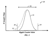
- FIG. 3 shows a graph of the expected distribution curve of ripple counter values.
- a digital process monitor calculates a value that correlates to the process variations of the ASIC (i.e., the delay in pulse signal). This value may be stored inside the ASIC and read via a register access.
- FIG. 2 shows a block diagram of one embodiment of the present invention.
- the digital process monitor 10 includes: a register interface and control block 12 ; a ring oscillator 14 ; an asynchronous ripple counter 16 ; and a local counter 20 .
- the local counter 20 could be either an “up” counter or a “down” counter in alternative embodiments.
- the register interface and control block 12 acts as a conduit to the rest of the ASIC.
- the interface 12 receives the chip clock signal (CLK), the start command (DPM_START), and the period of the test cycle (DPM_COUNT_DOWN) as input from the integrated circuit and it generates the completion signal (DPM_DONE) and the value that correlates to the process variation (DPM_COUNT).
- CLK chip clock signal
- DPM_START the start command
- DPM_COUNT_DOWN the period of the test cycle
- the ring oscillator 14 represents the chain of silicon gates to be tested within the circuit.
- the control block 12 receives DPM_START, it will generate a[n] starting signal (ENABLE) for the ring oscillator 14 .
- the oscillator 14 Upon receiving ENABLE, the oscillator 14 begins clocking 18 (RING_OSC_CLK) the asynchronous ripple counter 16 and the control block 12 . Meanwhile, DPM_START along with DPM_COUNT_DOWN are received by the local counter 20 . Upon receipt of DPM_START, the counter 20 will begin to clock (according to CLK) for the duration of DPM_COUNT_DOWN. After 2 DPM — COUNT —DOWN clock cycles, the counter 20 reaches zero and DPM_DONE is sent to the control block 12 which stops the process. The DPM_COUNT value is sent from the ripple counter 16 to the control block 12 and on to the register (not shown). Finally, the oscillator 14 is stopped with the SYNC_STOP signal and the ripple counter 16 is “zeroed” by the. RESET signal.
- the DPM_COUNT value could be serially scanned out using an IEEE 1149.1 bus.
- the DPM could be used as an “on-chip” tester so that it can be read over any range of environmental conditions wherever the circuit is used.
- the DPM could be located on the printed circuit board (PCB) of the target system.
- the functions of the interface, control block, oscillator, and both counters could be combined or separated in numerous combinations.
- the block diagram of FIG. 2 is merely an example of one way of breaking down the functions by component.
- the ripple counter may be synthesized using Flip-flop circuits.
- Flip-flop circuits One example of such circuits that may be used are D-type Negative Edge Asynchronous Reset Flip-flops.
- Flip-flops typically have minimum clock pulse width specification. This would require that the minimum pulse width of the ring oscillator must not exceed minimum pulse width of the flip-flops in the ripple counter. Additionally, the maximum clock frequency of the ring oscillator should not exceed the minimum chip clock frequency used to clock the local counter. This prevents the ripple counter from overflowing.
- the ring oscillator should be arranged with a fully representative selection of transistor logic gates (“cells”) from the cell library (i.e., the available set of cells within the integrated circuit) and use an interconnect range that is representative of the local interconnection.
- the interconnect range is the physical distance of the connection between the cells that are used. This range has a significant impact on the speed of the cells.
- a design example of one embodiment of a DPM using a 0.18 ⁇ m cell library has the following criteria:
- Chip Clock Period 2.0 ns
- the resolution of the DPM can be calculated by using the maximum (i.e., worst case) operating conditions as follows:
- SPICE analysis is performed with all of these criteria to calculate an accurate number for the ring oscillator clock frequency at minimum and maximum conditions.
- SPICE is an auxiliary circuit simulator that is well known to those of ordinary skill in the art. SPICE will make a primitive model and prediction of the performance of the silicon logic gates of the circuit. In this instance, it is used to simulate the best and worse case of the ring oscillator frequency. The frequency range can then be used to determine a PVT range window for the ripple counter values.
- FIG. 3 shows a graph 22 of the expected distribution curve 24 of ripple counter values.
- the PVT range window 26 is established between the best case conditions 28 and the worse case conditions 30 .
- the curve 24 is generated as ripple counter values (x-axis) are collected for a number of sample chips (y-axis). This can be done as part of a manufacturing process testing procedure. If the ripple counter value falls within the PVT window 26 , the circuit is performing within its designed range. However, if the value falls outside the window 32 , the circuit is outside the design range which causes incorrect operation within the system. Such a result may be caused by various problems such as process voltage or temperature shifts outside the design range. Additionally, if the ripple counter value is read after the circuit is already in service, the behavior of the cells may have degraded over time due to process degradation.
- the monitor may be used to analyze noise in the system.
- the power supply is the most common source of such. noise.
- the variations in the power supply voltage will cause degradation in the circuit timing. Such variations will show up as being outside the design criteria window.
- the advantages of the disclosed invention includes one or more of the following: a digital process monitor that is internal to the system and calculates a value that correlates to the process variations of the integrated circuit.
Abstract
Description
| CELL TYPE | % OF USAGE | ||
| Inverter | 30 | ||
| 2- |
20 | ||
| 2-Input NOR | 15 | ||
| 2:1 Inverting MUX | 15 | ||
| 2-Input OR | 5 | ||
| 2-Input XNOR | 5 | ||
| 2-Input AND | 5 | ||
| 2-Input XOR | 5 | ||
Claims (10)
Priority Applications (1)
| Application Number | Priority Date | Filing Date | Title |
|---|---|---|---|
| US09/709,970 US6668346B1 (en) | 2000-11-10 | 2000-11-10 | Digital process monitor |
Applications Claiming Priority (1)
| Application Number | Priority Date | Filing Date | Title |
|---|---|---|---|
| US09/709,970 US6668346B1 (en) | 2000-11-10 | 2000-11-10 | Digital process monitor |
Publications (1)
| Publication Number | Publication Date |
|---|---|
| US6668346B1 true US6668346B1 (en) | 2003-12-23 |
Family
ID=29737176
Family Applications (1)
| Application Number | Title | Priority Date | Filing Date |
|---|---|---|---|
| US09/709,970 Expired - Lifetime US6668346B1 (en) | 2000-11-10 | 2000-11-10 | Digital process monitor |
Country Status (1)
| Country | Link |
|---|---|
| US (1) | US6668346B1 (en) |
Cited By (25)
| Publication number | Priority date | Publication date | Assignee | Title |
|---|---|---|---|---|
| US20070001682A1 (en) * | 2005-06-30 | 2007-01-04 | International Business Machines Corporation | Method and structure for chip-level testing of wire delay independent of silicon delay |
| US20070214377A1 (en) * | 2006-03-08 | 2007-09-13 | Freescale Semiconductor, Inc. | Dynamic timing adjustment in a circuit device |
| US7348857B1 (en) | 2005-02-28 | 2008-03-25 | Marvell Semiconductor Israel Ltd. | Monitoring and compensating for real time local circuit speed in an integrated circuit |
| US20090251223A1 (en) * | 2008-04-02 | 2009-10-08 | Nassif Sani R | Techniques for characterizing performance of transistors in integrated circuit devices |
| US7739531B1 (en) * | 2005-03-04 | 2010-06-15 | Nvidia Corporation | Dynamic voltage scaling |
| US7849332B1 (en) | 2002-11-14 | 2010-12-07 | Nvidia Corporation | Processor voltage adjustment system and method |
| US7882369B1 (en) | 2002-11-14 | 2011-02-01 | Nvidia Corporation | Processor performance adjustment system and method |
| US7886164B1 (en) | 2002-11-14 | 2011-02-08 | Nvidia Corporation | Processor temperature adjustment system and method |
| US20110074398A1 (en) * | 2009-09-25 | 2011-03-31 | Barton Aaron M | Methods and sytems to detect voltage changes within integrated circuits |
| US8159241B1 (en) | 2007-04-24 | 2012-04-17 | Marvell International Ltd. | Method and apparatus for on-chip adjustment of chip characteristics |
| US8164390B1 (en) | 2007-03-14 | 2012-04-24 | Marvell International Ltd. | Regulating an operating condition of an integrated circuit to compensate for a manufacturing variation |
| CN101334440B (en) * | 2007-06-26 | 2012-06-13 | 东部高科股份有限公司 | Measurement apparatus for improving performance of standard cell library |
| US8354857B1 (en) | 2009-02-25 | 2013-01-15 | Marvell Israel (M.I.S.L) Ltd. | Method and apparatus for speed monitoring |
| US8370663B2 (en) | 2008-02-11 | 2013-02-05 | Nvidia Corporation | Power management with dynamic frequency adjustments |
| US8451047B2 (en) | 2011-05-17 | 2013-05-28 | Issc Technologies Corp. | Circuit used for indicating process corner and extreme temperature |
| US8839006B2 (en) | 2010-05-28 | 2014-09-16 | Nvidia Corporation | Power consumption reduction systems and methods |
| US9088288B1 (en) | 2009-02-25 | 2015-07-21 | Marvell Israel (M.I.S.L.) Ltd. | Method and apparatus for clock generator |
| US9106233B1 (en) | 2009-02-25 | 2015-08-11 | Marvell Israel (M.I.S.L) Ltd. | Method and apparatus for synchronization |
| US9134782B2 (en) | 2007-05-07 | 2015-09-15 | Nvidia Corporation | Maintaining optimum voltage supply to match performance of an integrated circuit |
| US9256265B2 (en) | 2009-12-30 | 2016-02-09 | Nvidia Corporation | Method and system for artificially and dynamically limiting the framerate of a graphics processing unit |
| US20160091560A1 (en) * | 2014-09-25 | 2016-03-31 | Taiwan Semiconductor Manufacturing Company, Ltd. | Integrated circuit and method of testing |
| CN105527560A (en) * | 2016-01-11 | 2016-04-27 | 福州瑞芯微电子股份有限公司 | Chip difference monitoring method and monitoring circuit |
| CN105680852A (en) * | 2016-01-11 | 2016-06-15 | 福州瑞芯微电子股份有限公司 | Chip internal clock generation and difference detection method and circuit |
| US9490817B1 (en) | 2009-02-25 | 2016-11-08 | Marvell Israel (M.I.S.L) Ltd. | Method and apparatus for gals system |
| US9830889B2 (en) | 2009-12-31 | 2017-11-28 | Nvidia Corporation | Methods and system for artifically and dynamically limiting the display resolution of an application |
Citations (9)
| Publication number | Priority date | Publication date | Assignee | Title |
|---|---|---|---|---|
| US5438599A (en) * | 1993-09-30 | 1995-08-01 | Lsi Logic Corporation | Self-calibration timing circuit |
| US5737342A (en) * | 1996-05-31 | 1998-04-07 | Quantum Corporation | Method for in-chip testing of digital circuits of a synchronously sampled data detection channel |
| US5867033A (en) * | 1996-05-24 | 1999-02-02 | Lsi Logic Corporation | Circuit for testing the operation of a semiconductor device |
| US5966021A (en) * | 1996-04-03 | 1999-10-12 | Pycon, Inc. | Apparatus for testing an integrated circuit in an oven during burn-in |
| US6115443A (en) * | 1998-10-28 | 2000-09-05 | Winbond Electronics Corp. | Programmable frequency following device |
| US6124143A (en) * | 1998-01-26 | 2000-09-26 | Lsi Logic Corporation | Process monitor circuitry for integrated circuits |
| US6378098B1 (en) * | 1998-03-19 | 2002-04-23 | Advantest Corp. | Semiconductor test system |
| US6396312B1 (en) * | 2000-08-11 | 2002-05-28 | Agilent Technologies, Inc. | Gate transition counter |
| US6463562B1 (en) * | 1999-04-06 | 2002-10-08 | Nec Corporation | Semiconductor device including macros and its testing method |
-
2000
- 2000-11-10 US US09/709,970 patent/US6668346B1/en not_active Expired - Lifetime
Patent Citations (9)
| Publication number | Priority date | Publication date | Assignee | Title |
|---|---|---|---|---|
| US5438599A (en) * | 1993-09-30 | 1995-08-01 | Lsi Logic Corporation | Self-calibration timing circuit |
| US5966021A (en) * | 1996-04-03 | 1999-10-12 | Pycon, Inc. | Apparatus for testing an integrated circuit in an oven during burn-in |
| US5867033A (en) * | 1996-05-24 | 1999-02-02 | Lsi Logic Corporation | Circuit for testing the operation of a semiconductor device |
| US5737342A (en) * | 1996-05-31 | 1998-04-07 | Quantum Corporation | Method for in-chip testing of digital circuits of a synchronously sampled data detection channel |
| US6124143A (en) * | 1998-01-26 | 2000-09-26 | Lsi Logic Corporation | Process monitor circuitry for integrated circuits |
| US6378098B1 (en) * | 1998-03-19 | 2002-04-23 | Advantest Corp. | Semiconductor test system |
| US6115443A (en) * | 1998-10-28 | 2000-09-05 | Winbond Electronics Corp. | Programmable frequency following device |
| US6463562B1 (en) * | 1999-04-06 | 2002-10-08 | Nec Corporation | Semiconductor device including macros and its testing method |
| US6396312B1 (en) * | 2000-08-11 | 2002-05-28 | Agilent Technologies, Inc. | Gate transition counter |
Cited By (39)
| Publication number | Priority date | Publication date | Assignee | Title |
|---|---|---|---|---|
| US7882369B1 (en) | 2002-11-14 | 2011-02-01 | Nvidia Corporation | Processor performance adjustment system and method |
| US7886164B1 (en) | 2002-11-14 | 2011-02-08 | Nvidia Corporation | Processor temperature adjustment system and method |
| US7849332B1 (en) | 2002-11-14 | 2010-12-07 | Nvidia Corporation | Processor voltage adjustment system and method |
| US7348857B1 (en) | 2005-02-28 | 2008-03-25 | Marvell Semiconductor Israel Ltd. | Monitoring and compensating for real time local circuit speed in an integrated circuit |
| US7893776B1 (en) | 2005-02-28 | 2011-02-22 | Marvell Israel (M.I.S.L) Ltd. | Monitoring and compensating for real time local circuit speed in an integrated circuit |
| US7714670B1 (en) | 2005-02-28 | 2010-05-11 | Marvell Israel (M.I.S.L.) Ltd. | Monitoring and compensating for real time local circuit speed in an integrated circuit |
| US7739531B1 (en) * | 2005-03-04 | 2010-06-15 | Nvidia Corporation | Dynamic voltage scaling |
| US20070001682A1 (en) * | 2005-06-30 | 2007-01-04 | International Business Machines Corporation | Method and structure for chip-level testing of wire delay independent of silicon delay |
| US7489204B2 (en) | 2005-06-30 | 2009-02-10 | International Business Machines Corporation | Method and structure for chip-level testing of wire delay independent of silicon delay |
| US7716511B2 (en) | 2006-03-08 | 2010-05-11 | Freescale Semiconductor, Inc. | Dynamic timing adjustment in a circuit device |
| US20070214377A1 (en) * | 2006-03-08 | 2007-09-13 | Freescale Semiconductor, Inc. | Dynamic timing adjustment in a circuit device |
| US8164390B1 (en) | 2007-03-14 | 2012-04-24 | Marvell International Ltd. | Regulating an operating condition of an integrated circuit to compensate for a manufacturing variation |
| US9766966B1 (en) | 2007-04-24 | 2017-09-19 | Marvell International Ltd. | Method and apparatus for on-chip adjustment of chip characteristics |
| US8159241B1 (en) | 2007-04-24 | 2012-04-17 | Marvell International Ltd. | Method and apparatus for on-chip adjustment of chip characteristics |
| US9134782B2 (en) | 2007-05-07 | 2015-09-15 | Nvidia Corporation | Maintaining optimum voltage supply to match performance of an integrated circuit |
| CN101334440B (en) * | 2007-06-26 | 2012-06-13 | 东部高科股份有限公司 | Measurement apparatus for improving performance of standard cell library |
| US8370663B2 (en) | 2008-02-11 | 2013-02-05 | Nvidia Corporation | Power management with dynamic frequency adjustments |
| US8775843B2 (en) | 2008-02-11 | 2014-07-08 | Nvidia Corporation | Power management with dynamic frequency adjustments |
| US20090251223A1 (en) * | 2008-04-02 | 2009-10-08 | Nassif Sani R | Techniques for characterizing performance of transistors in integrated circuit devices |
| US9973331B1 (en) | 2009-02-25 | 2018-05-15 | Marvell Israel (M.L.S.L) Ltd. | Method and apparatus for synchronization |
| US8354857B1 (en) | 2009-02-25 | 2013-01-15 | Marvell Israel (M.I.S.L) Ltd. | Method and apparatus for speed monitoring |
| US9490817B1 (en) | 2009-02-25 | 2016-11-08 | Marvell Israel (M.I.S.L) Ltd. | Method and apparatus for gals system |
| US9584136B1 (en) | 2009-02-25 | 2017-02-28 | Marvell Israel (M.I.S.L) Ltd. | Method and apparatus for synchronization |
| US9088288B1 (en) | 2009-02-25 | 2015-07-21 | Marvell Israel (M.I.S.L.) Ltd. | Method and apparatus for clock generator |
| US9106233B1 (en) | 2009-02-25 | 2015-08-11 | Marvell Israel (M.I.S.L) Ltd. | Method and apparatus for synchronization |
| US8368385B2 (en) * | 2009-09-25 | 2013-02-05 | Intel Corporation | Methods and systems to detect voltage changes within integrated circuits |
| US20110074398A1 (en) * | 2009-09-25 | 2011-03-31 | Barton Aaron M | Methods and sytems to detect voltage changes within integrated circuits |
| US9256265B2 (en) | 2009-12-30 | 2016-02-09 | Nvidia Corporation | Method and system for artificially and dynamically limiting the framerate of a graphics processing unit |
| US9830889B2 (en) | 2009-12-31 | 2017-11-28 | Nvidia Corporation | Methods and system for artifically and dynamically limiting the display resolution of an application |
| US8839006B2 (en) | 2010-05-28 | 2014-09-16 | Nvidia Corporation | Power consumption reduction systems and methods |
| US8451047B2 (en) | 2011-05-17 | 2013-05-28 | Issc Technologies Corp. | Circuit used for indicating process corner and extreme temperature |
| US9768762B2 (en) * | 2014-09-25 | 2017-09-19 | Taiwan Semiconductor Manufacturing Company, Ltd. | Integrated circuit and method of testing |
| US20160091560A1 (en) * | 2014-09-25 | 2016-03-31 | Taiwan Semiconductor Manufacturing Company, Ltd. | Integrated circuit and method of testing |
| US10707853B2 (en) | 2014-09-25 | 2020-07-07 | Taiwan Semiconductor Manufacturing Company, Ltd. | Integrated circuit and method of testing |
| US11374561B2 (en) | 2014-09-25 | 2022-06-28 | Taiwan Semiconductor Manufacturing Company, Ltd. | Integrated circuit and method of testing |
| CN105680852A (en) * | 2016-01-11 | 2016-06-15 | 福州瑞芯微电子股份有限公司 | Chip internal clock generation and difference detection method and circuit |
| CN105527560A (en) * | 2016-01-11 | 2016-04-27 | 福州瑞芯微电子股份有限公司 | Chip difference monitoring method and monitoring circuit |
| CN105527560B (en) * | 2016-01-11 | 2018-05-25 | 福州瑞芯微电子股份有限公司 | The monitoring method and observation circuit of chip differences |
| CN105680852B (en) * | 2016-01-11 | 2018-08-07 | 福州瑞芯微电子股份有限公司 | A kind of chip interior clock generates and otherness detection method and circuit |
Similar Documents
| Publication | Publication Date | Title |
|---|---|---|
| US6668346B1 (en) | Digital process monitor | |
| US5923676A (en) | Bist architecture for measurement of integrated circuit delays | |
| US10671784B2 (en) | Transient IR-drop waveform measurement system and method for high speed integrated circuit | |
| US5083299A (en) | Tester for measuring signal propagation delay through electronic components | |
| US6661266B1 (en) | All digital built-in self-test circuit for phase-locked loops | |
| US8368385B2 (en) | Methods and systems to detect voltage changes within integrated circuits | |
| US7408371B2 (en) | Apparatus for measuring on-chip characteristics in semiconductor circuits and related methods | |
| US6670800B2 (en) | Timing variation measurements | |
| US6081484A (en) | Measuring signals in a tester system | |
| US20080231297A1 (en) | Method for calibrating semiconductor device tester | |
| Pei et al. | A high-precision on-chip path delay measurement architecture | |
| US20100107026A1 (en) | Semiconductor device having built-in self-test circuit and method of testing the same | |
| EP1148340B1 (en) | All digital built-in self-test circuit for phase-locked loops | |
| CN108845224A (en) | Hit detection device and hit detection method | |
| US20120197570A1 (en) | Measurement of Parameters Within an Integrated Circuit Chip Using a Nano-Probe | |
| Noguchi et al. | A small-delay defect detection technique for dependable LSIs | |
| US7065684B1 (en) | Circuits and methods for measuring signal propagation delays on integrated circuits | |
| US20060195737A1 (en) | System and method for characterization of certain operating characteristics of devices | |
| US7386407B2 (en) | Semiconductor device test method using an evaluation LSI | |
| KR900008788B1 (en) | Semiconductor integrated circuit device having testing circuit | |
| JP3058130B2 (en) | Test circuit for high-speed semiconductor integrated circuit devices | |
| Cazeaux et al. | Novel on-chip circuit for jitter testing in high-speed PLLs | |
| Zhang et al. | An on-chip binning sensor for low-cost and accurate speed binning | |
| US9344075B2 (en) | Measuring delay between signal edges of different signals using an undersampling clock | |
| US6647538B1 (en) | Apparatus and method for signal skew characterization utilizing clock division |
Legal Events
| Date | Code | Title | Description |
|---|---|---|---|
| AS | Assignment |
Owner name: SUN MICROSYSTEMS, INC., CALIFORNIA Free format text: ASSIGNMENT OF ASSIGNORS INTEREST;ASSIGNORS:SCHULZ, JURGEN M.;QUAN, TAI;SMITH, BRIAN L.;AND OTHERS;REEL/FRAME:011297/0345;SIGNING DATES FROM 20001101 TO 20001109 |
|
| STCF | Information on status: patent grant |
Free format text: PATENTED CASE |
|
| FPAY | Fee payment |
Year of fee payment: 4 |
|
| FPAY | Fee payment |
Year of fee payment: 8 |
|
| FPAY | Fee payment |
Year of fee payment: 12 |
|
| AS | Assignment |
Owner name: ORACLE AMERICA, INC., CALIFORNIA Free format text: MERGER AND CHANGE OF NAME;ASSIGNORS:ORACLE USA, INC.;SUN MICROSYSTEMS, INC.;ORACLE AMERICA, INC.;REEL/FRAME:037278/0746 Effective date: 20100212 |