EP2096470A1 - Systems and method for supplemental weather information presentation on a display - Google Patents
Systems and method for supplemental weather information presentation on a display Download PDFInfo
- Publication number
- EP2096470A1 EP2096470A1 EP08172027A EP08172027A EP2096470A1 EP 2096470 A1 EP2096470 A1 EP 2096470A1 EP 08172027 A EP08172027 A EP 08172027A EP 08172027 A EP08172027 A EP 08172027A EP 2096470 A1 EP2096470 A1 EP 2096470A1
- Authority
- EP
- European Patent Office
- Prior art keywords
- weather information
- supplemental
- supplemental weather
- display
- aircraft
- Prior art date
- Legal status (The legal status is an assumption and is not a legal conclusion. Google has not performed a legal analysis and makes no representation as to the accuracy of the status listed.)
- Granted
Links
- 230000000153 supplemental effect Effects 0.000 title claims abstract description 155
- 238000000034 method Methods 0.000 title claims description 12
- 230000004044 response Effects 0.000 claims description 4
- 238000012545 processing Methods 0.000 claims description 3
- 238000004891 communication Methods 0.000 description 19
- 230000000875 corresponding effect Effects 0.000 description 16
- 230000015654 memory Effects 0.000 description 11
- 230000010354 integration Effects 0.000 description 9
- 238000010586 diagram Methods 0.000 description 7
- 239000003086 colorant Substances 0.000 description 6
- 238000001514 detection method Methods 0.000 description 5
- 238000005259 measurement Methods 0.000 description 4
- 208000034953 Twin anemia-polycythemia sequence Diseases 0.000 description 3
- 230000000694 effects Effects 0.000 description 3
- 230000001133 acceleration Effects 0.000 description 2
- 230000002596 correlated effect Effects 0.000 description 2
- 230000003213 activating effect Effects 0.000 description 1
- 230000002411 adverse Effects 0.000 description 1
- 230000009286 beneficial effect Effects 0.000 description 1
- 230000012447 hatching Effects 0.000 description 1
- 238000009434 installation Methods 0.000 description 1
- 238000001556 precipitation Methods 0.000 description 1
- 238000002310 reflectometry Methods 0.000 description 1
Images
Classifications
-
- G—PHYSICS
- G01—MEASURING; TESTING
- G01W—METEOROLOGY
- G01W1/00—Meteorology
- G01W1/02—Instruments for indicating weather conditions by measuring two or more variables, e.g. humidity, pressure, temperature, cloud cover or wind speed
-
- G—PHYSICS
- G01—MEASURING; TESTING
- G01S—RADIO DIRECTION-FINDING; RADIO NAVIGATION; DETERMINING DISTANCE OR VELOCITY BY USE OF RADIO WAVES; LOCATING OR PRESENCE-DETECTING BY USE OF THE REFLECTION OR RERADIATION OF RADIO WAVES; ANALOGOUS ARRANGEMENTS USING OTHER WAVES
- G01S13/00—Systems using the reflection or reradiation of radio waves, e.g. radar systems; Analogous systems using reflection or reradiation of waves whose nature or wavelength is irrelevant or unspecified
- G01S13/88—Radar or analogous systems specially adapted for specific applications
- G01S13/95—Radar or analogous systems specially adapted for specific applications for meteorological use
-
- G—PHYSICS
- G01—MEASURING; TESTING
- G01S—RADIO DIRECTION-FINDING; RADIO NAVIGATION; DETERMINING DISTANCE OR VELOCITY BY USE OF RADIO WAVES; LOCATING OR PRESENCE-DETECTING BY USE OF THE REFLECTION OR RERADIATION OF RADIO WAVES; ANALOGOUS ARRANGEMENTS USING OTHER WAVES
- G01S7/00—Details of systems according to groups G01S13/00, G01S15/00, G01S17/00
- G01S7/003—Transmission of data between radar, sonar or lidar systems and remote stations
-
- G—PHYSICS
- G01—MEASURING; TESTING
- G01S—RADIO DIRECTION-FINDING; RADIO NAVIGATION; DETERMINING DISTANCE OR VELOCITY BY USE OF RADIO WAVES; LOCATING OR PRESENCE-DETECTING BY USE OF THE REFLECTION OR RERADIATION OF RADIO WAVES; ANALOGOUS ARRANGEMENTS USING OTHER WAVES
- G01S7/00—Details of systems according to groups G01S13/00, G01S15/00, G01S17/00
- G01S7/02—Details of systems according to groups G01S13/00, G01S15/00, G01S17/00 of systems according to group G01S13/00
- G01S7/04—Display arrangements
- G01S7/06—Cathode-ray tube displays or other two dimensional or three-dimensional displays
-
- G—PHYSICS
- G01—MEASURING; TESTING
- G01W—METEOROLOGY
- G01W1/00—Meteorology
- G01W1/08—Adaptations of balloons, missiles, or aircraft for meteorological purposes; Radiosondes
-
- Y—GENERAL TAGGING OF NEW TECHNOLOGICAL DEVELOPMENTS; GENERAL TAGGING OF CROSS-SECTIONAL TECHNOLOGIES SPANNING OVER SEVERAL SECTIONS OF THE IPC; TECHNICAL SUBJECTS COVERED BY FORMER USPC CROSS-REFERENCE ART COLLECTIONS [XRACs] AND DIGESTS
- Y02—TECHNOLOGIES OR APPLICATIONS FOR MITIGATION OR ADAPTATION AGAINST CLIMATE CHANGE
- Y02A—TECHNOLOGIES FOR ADAPTATION TO CLIMATE CHANGE
- Y02A90/00—Technologies having an indirect contribution to adaptation to climate change
- Y02A90/10—Information and communication technologies [ICT] supporting adaptation to climate change, e.g. for weather forecasting or climate simulation
Definitions
- RADAR on-board weather radio detection and ranging
- radar on-board weather radio detection and ranging
- Existing on-board weather radar systems provide data on weather local to the aircraft, for example, weather ahead of the aircraft within the range of the weather radar unit. The weather information is displayed on a cockpit weather display.
- weather data collected by an aircraft is available only to the particular aircraft experiencing the weather since the weather phenomena is detected by the on-board radar system. That is, weather information displayed on on-board cockpit radar displays is limited to the weather returns supplied by the on-board weather radar.
- Such supplemental weather information may be particularly beneficial if the weather information related to weather phenomena not readily detectable by the on-board radar system, such as turbulence.
- a remote aircraft may pass through a region of turbulence that is not identified by the radar system. Acceleration sensors or motion sensors may identify the turbulence.
- PIREP pilot report
- legacy on-board radar systems cannot receive and display such supplemental weather information and present such on their on-board cockpit radar displays because they are not configured to receive and interpret PIREPs.
- the legacy on-board radar system must be removed and replaced with a new on-board radar system having the capacity to receive and display such supplemental weather information. Refitting an aircraft with a new on-board radar system is very expensive and time consuming. Accordingly, it is desirable to provide legacy on-board radar systems with the ability to receive and present supplemental weather information on their on-board cockpit radar displays.
- EFB electronic flight bag
- EFB electronic travel bag
- EFBs are connectable to aviation electronics of the airplane via ports, busses, or other suitable connectors.
- Some EFBs may include a display. At times, it may be desirable to have the EFB display present the supplemental weather information on its radar display.
- An exemplary embodiment has an input interface communicatively coupled to the radar system and operable to receive the detected weather information from the radar system, and communicatively coupled to a communication management unit that receives the supplemental weather information from a source that is remote to a craft; a processor system communicatively coupled to the input interface, and operable to integrate the weather information and the supplemental weather information, and a display communicatively coupled to the processor system and operable to display the integrated weather phenomena and supplemental weather information.
- an exemplary embodiment is a system that has a radar system operable to detect weather phenomena in a vicinity of a craft and operable to generate weather information corresponding to the detected weather phenomena; a transceiver operable to receive supplemental weather information from a remote source; a processor system communicatively coupled to the radar system and the transceiver, and operable to integrate the weather information and the supplemental weather information; and a display communicatively coupled to the processor system and operable to display the integrated weather information and supplemental weather information.
- an exemplary embodiment is a process that receives the supplemental weather information from a remote source, determines a location of the supplemental weather information relative to the craft, receives weather information from an on-board radar system, and integrates the supplemental weather information with the weather information received from the on-board radar system.
- FIGURE 1 is a conceptual illustration of aircraft receiving and communicating weather-related information
- FIGURE 2 is a conceptual illustration of the aircraft of FIGURE 1 from a top view perspective
- FIGURE 3 is a conceptual illustration of data corresponding to three radials of ARINC 453 data presented on a radar display
- FIGURE 4 is a conceptual illustration of radar data generated under the ARINC 453 format
- FIGURE 5 is a block diagram of a supplemental weather display system embodiment
- FIGURE 6 is a block diagram of a communication management unit in the supplemental weather display system embodiment.
- FIGURES 7 and 8 are block diagrams of alternative embodiments of the supplemental weather display system.
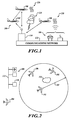
- FIGURE 1 is a conceptual illustration of aircraft receiving and communicating weather-related information.
- An aircraft 102 is equipped with an embodiment of a supplemental weather display system 100.
- FIGURE 2 is a conceptual illustration of the aircraft 102 of FIGURE 1 from a top view perspective.
- Weather data is collected from a plurality of sources. These sources may be terrestrial weather instrumentation 104 equipped with terrestrial sensors that may include weather radar, local observations and other Earth-based sensors commonly known to those of skill in the art. Weather data may also be collected by a plurality of aircraft 106, 108. The data collected from aircraft 106, 108 is preferably collected by using standard instrumentation already carried aboard the aircraft 106, 108. This standard instrumentation typically includes, but is not limited to: a weather radar, a storm scope, navigation systems, motion sensors, and/or an air data computer. The type of weather data available can include, depending upon sensor availability, the following:
- a ground station 110 receives the weather data via downlink and/or via communications backbone 112.
- Ground station 110 may also incorporate into the compiled data any available turbulence and pilot reports (PIREPS), referred to herein as TAPS information, from aircraft 106, 108.
- PIREPS turbulence and pilot reports
- the ground station 110 then processes the available weather data for uplink to the aircraft 102 equipped with an embodiment of the supplemental weather display system 100.
- Some embodiments are operable to receive supplemental weather information directly from other aircraft.
- Other embodiments are operable to receive supplemental weather information from on-board detection systems, such as, but not limtied to, a lightning detection system.
- the supplemental weather information received by the aircraft 102 is then processed for display on a cockpit display.
- the various threat conditions are communicated to the pilot by drawing icons on the display, such as patterned polygons, for example.
- the pilot sees a series of two-dimensional figures in a plan view so the pilot can easily see the relationship of his short-term flight path to nearby meteorological threats.
- FIGURE 2 conceptually illustrates the range 202 of the on-board weather radar system of aircraft 102. Since the thunderstorm 114 is within the range 202 of the on-board weather radar system, the radar display would indicate the presence and/or severity of the thunderstorm 114.
- Some types of weather phenomena are not detectable (or at least not detectable with suitable reliability) by the on-board weather radar system of the aircraft 102.
- One exemplary type of such weather phenomena is turbulence.
- turbulence is detectable by an aircraft passing through such turbulence.
- the aircraft 106 is illustrated as passing through turbulence 116. Sensors on the aircraft 106 detect the turbulence 116. Information corresponding to the detected turbulence 116 is communicated to the ground station 110.
- the aircraft 108 is passing through the turbulence 118. Sensors on the aircraft 108 detect the turbulence 118. Information corresponding to the detected turbulence 118 is communicated to the ground station 110.
- the terrestrial weather instrumentation 104 may detect the turbulence 118 and communicate information corresponding to the detected turbulence 118 to the ground station 110.
- the aircraft 106 and the aircraft 108 are within the range 202 of the on-board radar system of the aircraft 102.
- Embodiments of the supplemental weather display system 100 receive information corresponding to supplemental weather information, such as, but not limited to, the turbulence 116 and the turbulence 118.
- the supplemental weather information is presented on the on-board cockpit radar display of the aircraft 102 using suitable icons or the like.
- the supplemental weather information may be received from the ground station 110, or, from the aircraft 106 and/or the aircraft 108.
- supplemental weather display system 100 may be installed on any craft equipped with a weather radar system, such as an aircraft, boat, submarine, dirigible, automobile, or vehicle.
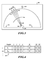
- FIGURE 3 is a conceptual illustration of data corresponding to three radials 302, 304, and 306 of ARINC 453 data presented on a radar display 300.
- the radar data is processed into a series of color information assigned to bins of a radial.
- the radials are presented in a serial manner moving across the display 300, the viewer perceives a sweeping-like presentation of the radar information as the radials are serially presented.
- a first bin 308 with a first color is visible at or near the origin 310.
- Colors are presented out along the radial up to the last bin 312.
- colors are indicative of the nature (e.g., severity) of the detected weather phenomena and/or other physical objects.
- the color black indicates an absence of weather phenomena (no returning reflected radar signal at that range).
- Other colors used are red, orange, blue and magenta.
- the colors presented in a radar image normally range from blue or green for weak returns, to red or magenta for very strong returns. Strong returns (red or magenta) may be indicative of heavy rain, thunderstorms, hail, strong winds, or tornadoes, however such information needs to be interpreted carefully.
- the radial 304 is next presented, followed by the radial 306. Presentation of the radials continues until the last radial is presented at the end 314 of the radar display 300. Presentation of the radials then begins at the beginning 316 of the radar display 300, and continues across the screen. Since the currently presented radial corresponds to a more recent acquisition of radar data than the preceding presented radials, the radar display 300 is refreshed with the most currently available radar information.
- the viewer since the location of a bin along any particular radial corresponds to proximity to the detecting radar system 300, the viewer understands that the presented data corresponding to the group of bins 320 corresponds to the detection of reflecting weather phenomena (and/or other physical objects) relatively close to the detecting radar system 300, and that the last of the bins 322 corresponds to the detection of reflecting weather phenomena (and/or other physical objects) relatively far away from the detecting radar system 300.
- the illustrated radar display 300 displays across a range of approximately 180°, with the arrow 318 corresponding to the front of the airplane in which the radar display 300 is installed.
- Other radar information presentation formats may be used, such as a 360° presentation wherein radar information surrounding the detecting radar system is displayed.
- Embodiments of the supplemental weather display system 100 may be operable with any suitable radar device or system.
- FIGURE 4 is a conceptual illustration of radar data 402 generated under the ARINC 453 format.
- Each radial i resides in a 1600 bit word that begins with a 64 bit header (Pi) followed by a series of 512 sub-words (3 bits each).
- the header (Pi) contains various presentation information pertaining to the radial, such as the angular orientation of the header on the radar display 300.
- the header (Pi) may contain a specified angle at which the corresponding radial is to be presented on the radar display 300.
- the location of the 3 bit sub-words in the word corresponds to the location along the radial i.
- the first sub-word (indicated as "1") contains the information that corresponds to presented first bin 308 ( FIGURE 3 ).
- the sub-words indicated as "1", “2", “3” and “4" in FIGURE 5 correspond to the first four presented bins 320 ( FIGURE 3 ).
- the last sub-word 512 corresponds to the last presented bin 312 ( FIGURE 3 ).
- the 3 bit sub-words contain color information corresponding to the characteristics of detected reflecting weather phenomena (and/or other physical objects). For example, a number in a bin may correspond to the color black to indicate that, for that range bin, no reflections from weather phenomena (and/or other physical objects) were detected.
- supplemental weather display system 100 may receive information formats and process information formats.
- a different number of range bins may be used, for example. Further, additional or alternative colors may be used. Some radar systems 300 may use only black and white colors.
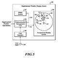
- FIGURE 5 is a block diagram of an exemplary embodiment of the supplemental weather display system 100.
- the exemplary supplemental weather display system 100 comprises a radar system 502, a communication management unit 504, a user interface 506, and a navigational display system 508.
- FIGURE 6 is a block diagram of the communication management unit 504 in the supplemental weather display system 100 of FIGURE 4 .
- the communication management unit 504 comprises a processor system 602, a radio frequency (RF) transceiver 604, an output interface 606, and input interface 608, and a memory 610.
- the memory 610 includes a portion for the supplemental weather integration logic 612 and a portion for the aircraft parameters 614. In some embodiments, the weather integration logic 612 and the aircraft parameters 614 may be stored in separate memories.
- the radar system 502 communicates supplemental weather information corresponding to detected weather phenomena to the communication management unit 504, via connector 516.
- the weather information is received by the input interface 608.
- input interface 608 is operable to receive the radar information in the ARINC 453 format from the radar system 502. Other embodiments communicate the radar information in other formats.
- the aircraft 106 detected the turbulence 116.
- the aircraft 108 detected the turbulence 118 ( FIGURE 1 ).
- the on-board radar system 502 detected the thunderstorm 114.
- the supplemental weather information is communicated from the aircraft 106 and the aircraft 108 to the ground station 110. After processing, the ground station 110 communicates a RF signal with the supplemental weather information to aircraft 102 equipped with an embodiment of the supplemental weather display system 100. (Alternatively, or additionally, the aircraft 106 and the aircraft 108 may directly communicate their supplemental weather information directly to aircraft 102.)
- the supplemental weather information is received by the RF transceiver 604 of the communications management unit 504. In alternative embodiments, other suitable RF receiving devices may be used.
- the supplemental weather information is received as an RF signal by RF transceiver 604.
- the processor system 602 retrieves and executes the supplemental weather integration logic 612 from memory 610 to integrate the supplemental weather information of the supplemental weather information signal with the weather information from the radar system 502.
- the integrated display information is communicated to display 300 via connector 518.
- the received supplemental weather information and the weather information from the radar system 502 are integrated together into a single display presentation such that the viewer of display 300 views the received supplemental weather information and the detected weather information.
- the supplemental weather information may be indicated using an icon that is recognizable to the viewer. For example, an icon 510 is presented on display 300 which indicates the presence of the turbulence 116 detected by the aircraft 106. A second icon 512 is presented on the display 300, which indicates the presence of the turbulence 118 detected by the aircraft 108.
- the detected thunderstorm 114 is indicated by an icon 514.
- the communication management unit 504 To integrate the received supplemental weather information and the information from radar system 502, the communication management unit 504 identifies which supplemental weather information, such as turbulence, is to be presented on display 300. The communication management unit 504 identifies which of the supplemental weather information is within the display range of the display 300. Weather information outside the display range may be deleted, ignored, deselected, etc. Weather information within the display range is further processed to determine if it should be integrated with the weather information from the radar system 502.
- the supplemental weather display system 100 correlates the location of the supplemental weather information within the display range with respect to the location of the aircraft 102. Accordingly, embodiments of the supplemental weather display system 100 determine where the icons corresponding to the supplemental weather information are to be displayed on the display 300. The supplemental weather information is then integrated with the weather information from the radar system 502 such that the integrated display information is generated.
- the integrated display information is communicated to the display 300 via the output interface 606.
- the integrated display information may be output in any suitable format.
- the integrated display information is in the ARINC 453 data format.
- the integrated display information is processed into a low bandwidth format, such as, but not limited to, an ARINC 429 data format.
- the location of the aircraft 106 is known (location of the aircraft 106 is specified by information in its TAPS, or the location is determined by ground-based radar). Accordingly, the location of the turbulence 116 is determinable. Since the location of the aircraft 102 is known to itself, the supplemental weather display system 100 determines the location of the detected turbulence 116 with respect to the current aircraft location. Upon determining the relative location of the turbulence 116, the supplemental weather display system 100 then determines the location on the display 300 where the icon 510 is to be displayed so as to indicate to a viewer the location of the turbulence 116 with respect to the aircraft 102.
- the weather information from the radar system 502 is an ARINC 453 compliant signal. Accordingly, the communication management unit 504 determines which ranges and bins correspond to the determined location of the supplemental weather information that is to be integrated with the detected weather information provided by the radar system 502. The communication management unit 504 then processes the bin information and provides information that corresponds to the icon representative of the supplemental weather information that is to be displayed on the display 300. For example, the bid data may be replaced, substituted, or the like, with data corresponding to the icon representative of the supplemental weather information.
- the user interface 506 is operable to receive input from a user such that the supplemental weather information is integrated with the weather information from the radar system 502 on a selectable basis.
- an actuator 520 or the like communicates a user input signal to the user interface 506 which indicates that the supplemental weather information is to be integrated with the weather information from the radar system 502.
- the user input signal from the actuator 520 may be modified by the user such that the supplemental weather information is not integrated with the weather information from the radar system 502.
- the user may choose to have the supplemental weather display system 100 integrate, or not integrate, the supplemental weather information with the weather information from the radar system 502.
- the actuator 520 may be operable to select the types of supplemental weather information to be integrated with the weather information from the radar system 502. For example, the user may desire to integrate turbulence information with the weather information from the radar system 502. Actuator 520 generates a signal that indicates that the turbulence information is to be selected from the received supplemental weather information. In some embodiments, a plurality of types of supplemental weather information may be selected for integration with the weather information from the radar system 502.
- actuator 520 examples include, but are not limited to, a pushbutton, a toggle-switch, a multi-position sensing device configured to sense a plurality of switch positions, a touch sensitive device, or a light sensitive device.
- the functionality of the actuator 520 may be alternatively implemented as a menu displayed on a display, such as display 300.
- the actuator 520 is a component of the communication management unit 504. If implemented on a menu-based system, a cursor, touch sensitive button, or the like, may be displayed on the display 300 for activating a user interface menu which displays selectable types of, or characteristics of, available supplemental weather information that is displayable on the display 300.
- Some embodiments of the supplemental weather display system 100 are operable to analyze the received supplemental weather information to determine if the supplemental weather information should be presented.
- one or more characteristics of the supplemental weather information is correlated with one or more characteristics of the aircraft 102. Characteristics of the aircraft 102 may be stored in the aircraft parameters 614 portion of memory 610.
- the supplemental weather display system 100 determines if the supplemental weather information will impact performance of the aircraft 102. In response to determining that the supplemental weather information will impact performance of the aircraft, the supplemental weather information is integrated with the weather information received from the on-board radar system 502.
- the size of the aircraft 102 may be larger than the size of the aircraft providing reporting of turbulence.
- the turbulence may be significant.
- the TAPS information from the relatively small aircraft includes information characterizing the strength of the turbulence and characteristics regarding the detecting aircraft.
- the supplemental weather display system 100 correlates the reported turbulence strength information with the size of the aircraft 102 to determine if the reported turbulence is likely to have a significant effect on the aircraft 102.
- the supplemental weather display system 100 may determine that the reported turbulence information should not be integrated with the weather information from the radar system 502. On the other hand, if the reported turbulence will likely affect the aircraft 102 (such as when the aircraft 102 is the same size or smaller than the aircraft reporting the turbulence), the supplemental weather display system 100 may determine that the reported turbulence information should be integrated with the weather information from the radar system 502.
- the supplemental weather display system 100 correlates the reported turbulence altitude with the altitude of the aircraft 102 to determine if the reported turbulence will have any significant effect on the aircraft 102. If the altitude of the reported turbulence is within a threshold of the altitude of the aircraft 102, the supplemental weather display system 100 may determine that the reported turbulence information should be integrated with the weather information from the radar system 502.
- the supplemental weather display system 100 may determine that the reported turbulence information should not be integrated with the weather information from the radar system 502 (since the aircraft 102 is not likely to encounter the turbulence in view of the altitude differences).
- Location of the reported supplemental weather information may also be an analyzed characteristic.
- the current heading, and/or a future heading, of the aircraft 102 may be correlated with the respective location of the supplemental weather information. If the aircraft 102 is traveling at a heading where the supplemental weather information is likely not to be encountered, the supplemental weather display system 100 may determine that the reported turbulence information should not be integrated with the weather information from the radar system 502. Accordingly, information that is not relevant to the immediate needs of the pilot is not presented on display 300.
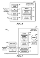
- FIGURE 7 is a block diagram of an alternative embodiment of the supplemental weather display system 100 implemented in a navigational display system 700.
- the user interface 506, the processor system 602, the input interface 608, and the memory 610 are included in the navigational display system 508.
- the memory 610 includes a portion for the supplemental weather integration logic 612 and an optional portion for the aircraft parameters 614.
- This embodiment allows a navigation display system 700 to be communicatively coupled to the radar system 502 and the communication management unit 504.
- the radar system 502 and the communication management unit 504 may be a legacy device installed in an existing aircraft. Accordingly, the aircraft 102 may be upgraded to have an embodiment of the supplemental weather display system 100 by replacing the legacy navigation display system 508 ( FIGURE 5 ) with the navigation display system 700.
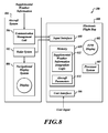
- FIGURE 8 is a block diagram of an alternative embodiment of the supplemental weather display system 100.
- Aircraft personnel may use various types of portable auxiliary equipment implemented with an embodiment of the supplemental weather display system 100.
- Such equipment may be commonly referred to as an "electronic flight bag” (EFB) or an “electronic travel bag” (ETB), generally referred to as an EFB 800 herein.
- EFB electronic flight bag
- EFB 800 electronic travel bag
- An EFB 800 is connectable to aviation electronics of the airplane via ports, busses, or other suitable connectors.
- the EFB 800 conforms its connection to communicate under the ARINC 429 standard, which is a relative low speed data protocol (particularly with respect to the ARINC 453 standard used by radars).
- ARINC 429 supports a low speed mode (12.5 to 14.5 kHz), or a high speed mode (100 kHz), data transfers based upon a 32 bit word structure.
- the EFB 800 may include a display 802. At times, it may be desirable to have the EFB display 802 present radar information integrated with supplemental weather information. Accordingly, the EFB 800 includes the user interface 506, the processor system 602, the input interface 608, and the memory 610. The memory 610 includes a portion for the supplemental weather integration logic 612 and an optional portion for the aircraft parameters 614. This embodiment allows the EFB 800 with an embodiment of the supplemental weather display system 100 to be communicatively coupled to the radar system 502 and the communication management unit 504. The radar system 502 and the communication management unit 504 may be legacy devices installed in an existing aircraft system 806. Thus, the radar system 502 remains coupled to the legacy navigational display system 508.
- processing time for the supplemental weather display system 100 to integrate the supplemental weather information with the weather information from the radar system 502 is preferably short enough so as not to cause a substantial delay in the refresh rate of the weather information from the radar system 502. That is, the time for integration of the selected supplemental weather display system 100 is preferably less than the update rate of the display 300.
- Embodiments may use one or more suitable icons to present a particular type of supplemental weather information.
- One embodiment may employ a rectangle that may have a particular hatching style, shading, and/or color to indicate characteristics of the integrated supplemental weather information.
- Another embodiment may use a series of arcs, bars or lines to display the supplemental weather information.
- characteristics of the displayed icon may indicate characteristics of the supplemental weather information. For example, the color and/or intensity of the displayed icon may indicate severity of the turbulence.
- Some embodiments may display supplemental textual information corresponding to characteristics of the supplemental weather information with the displayed icon.
- alpha-numeric text may indicate the altitude of the displayed supplemental weather information.
- Some embodiments are operable to allow a user to specify characteristics of the icon used to indicate the presence of the supplemental weather information. For example, the pilot may desire a relatively large and/or brightly colored icon that is easily discernable. Alternatively, a navigator may prefer a smaller, less noticeable icon. Thus, the actuator 616 is configured to allow the user to specify attributes of the displayed icon.
- the processor system 602 is typically a commercially available processor. Examples of commercially available processors include, but are not limited to, an 80x86 or Pentium series microprocessor from Intel Corporation, U.S.A., a PowerPC microprocessor from IBM., a Sparc microprocessor from Sun Microsystems, Inc., a PA-RISC series microprocessor from Hewlett-Packard Company, or a 68xxx series microprocessor from Motorola Corporation.
- the processor system 602 controls the execution of a program, employed by embodiments of the supplemental weather display system 100. Furthermore, for convenience of illustration in FIGURE 3 , the processor system 602, the memory 610, the supplemental weather integration logic 612, and the aircraft parameters 614 are shown residing in the communication management unit 504.
- the processor system 602, the memory 610, the supplemental weather integration logic 612, and/or the aircraft parameters 614 may reside in alternative convenient locations outside of the communication management unit 504, as components of other systems, or as stand alone dedicated elements, without adversely affecting the operation and functionality of the supplemental weather display system 100.
Abstract
Description
- Commercial aircraft employ on-board weather radio detection and ranging (RADAR, or commonly referred to as "radar") systems that detect weather phenomena and display such detected weather phenomena on a radar display. Existing on-board weather radar systems provide data on weather local to the aircraft, for example, weather ahead of the aircraft within the range of the weather radar unit. The weather information is displayed on a cockpit weather display. However, the weather data collected by an aircraft is available only to the particular aircraft experiencing the weather since the weather phenomena is detected by the on-board radar system. That is, weather information displayed on on-board cockpit radar displays is limited to the weather returns supplied by the on-board weather radar.
- Various techniques have been proposed to provide an aircraft weather information system wherein the weather information is provided to the aircraft from various sources external to the aircraft. For example, the commonly assigned
U.S. patent application Ser. No. 09/907,730 , published asU.S.2002/0379072 , entitled "AIRCRAFT WEATHER INFORMATION SYSTEM", and the commonly assignedU.S. patent 8,829,922, issued on December 7, 2004 , entitled "SYNTHETIC AIRBORNE HAZARD DISPLAY", both of which are incorporated herein by reference, propose providing weather related information detected by other aircraft and/or ground installations to the aircraft. Such supplemental information enhances the quality of weather information presented on the on-board cockpit radar displays. - Such supplemental weather information may be particularly beneficial if the weather information related to weather phenomena not readily detectable by the on-board radar system, such as turbulence. For example, a remote aircraft may pass through a region of turbulence that is not identified by the radar system. Acceleration sensors or motion sensors may identify the turbulence.
- Information corresponding to the detected turbulence is communicated to a ground station or to other aircraft using a pilot report (PIREP). Pilots of other aircraft may learn of the turbulence from the PIREP.
- However, legacy on-board radar systems cannot receive and display such supplemental weather information and present such on their on-board cockpit radar displays because they are not configured to receive and interpret PIREPs. To take advantage of such supplemental weather information, the legacy on-board radar system must be removed and replaced with a new on-board radar system having the capacity to receive and display such supplemental weather information. Refitting an aircraft with a new on-board radar system is very expensive and time consuming. Accordingly, it is desirable to provide legacy on-board radar systems with the ability to receive and present supplemental weather information on their on-board cockpit radar displays.
- Further, aircraft personnel may use various types of portable auxiliary equipment. Such equipment may be commonly referred to as an "electronic flight bag" (EFB) or an "electronic travel bag" (ETB), generally referred to as EFBs herein. EFBs are connectable to aviation electronics of the airplane via ports, busses, or other suitable connectors. Some EFBs may include a display. At times, it may be desirable to have the EFB display present the supplemental weather information on its radar display.
- Systems and methods of displaying supplemental weather information and weather detected by a radar system are disclosed. An exemplary embodiment has an input interface communicatively coupled to the radar system and operable to receive the detected weather information from the radar system, and communicatively coupled to a communication management unit that receives the supplemental weather information from a source that is remote to a craft; a processor system communicatively coupled to the input interface, and operable to integrate the weather information and the supplemental weather information, and a display communicatively coupled to the processor system and operable to display the integrated weather phenomena and supplemental weather information.
- In accordance with further aspects, an exemplary embodiment is a system that has a radar system operable to detect weather phenomena in a vicinity of a craft and operable to generate weather information corresponding to the detected weather phenomena; a transceiver operable to receive supplemental weather information from a remote source; a processor system communicatively coupled to the radar system and the transceiver, and operable to integrate the weather information and the supplemental weather information; and a display communicatively coupled to the processor system and operable to display the integrated weather information and supplemental weather information.
- In accordance with further aspects, an exemplary embodiment is a process that receives the supplemental weather information from a remote source, determines a location of the supplemental weather information relative to the craft, receives weather information from an on-board radar system, and integrates the supplemental weather information with the weather information received from the on-board radar system.
- Preferred and alternative embodiments are described in detail below with reference to the following drawings:
-
FIGURE 1 is a conceptual illustration of aircraft receiving and communicating weather-related information; -
FIGURE 2 is a conceptual illustration of the aircraft ofFIGURE 1 from a top view perspective; -
FIGURE 3 is a conceptual illustration of data corresponding to three radials of ARINC 453 data presented on a radar display; -
FIGURE 4 is a conceptual illustration of radar data generated under the ARINC 453 format; -
FIGURE 5 is a block diagram of a supplemental weather display system embodiment; -
FIGURE 6 is a block diagram of a communication management unit in the supplemental weather display system embodiment; and -
FIGURES 7 and8 are block diagrams of alternative embodiments of the supplemental weather display system. -
FIGURE 1 is a conceptual illustration of aircraft receiving and communicating weather-related information. Anaircraft 102 is equipped with an embodiment of a supplementalweather display system 100.FIGURE 2 is a conceptual illustration of theaircraft 102 ofFIGURE 1 from a top view perspective. - Weather data is collected from a plurality of sources. These sources may be
terrestrial weather instrumentation 104 equipped with terrestrial sensors that may include weather radar, local observations and other Earth-based sensors commonly known to those of skill in the art. Weather data may also be collected by a plurality ofaircraft aircraft aircraft - (a) Convective activity (e.g., from Doppler radar measurements);
- (b) Turbulence (e.g., from Doppler radar measurement/down linked acceleration data from
aircraft 106, 108); - (c) Winds aloft (e.g., from down linked data from other aircraft or ground stations);
- (d) High surface winds (e.g., from local measurements);
- (e) Icing conditions (e.g., from down linked data and/or infra red measurements);
- (f) Precipitation density (e.g., from ground and airborne radar reflectivity data);
- (g) Lightning (e.g., from Storm Scope or other sensor);
- (h) Cloud density (e.g., from satellite imagery); and
- (i) Volcanic Ash (e.g., from satellite imagery).
- A
ground station 110 receives the weather data via downlink and/or viacommunications backbone 112.Ground station 110 may also incorporate into the compiled data any available turbulence and pilot reports (PIREPS), referred to herein as TAPS information, fromaircraft ground station 110 then processes the available weather data for uplink to theaircraft 102 equipped with an embodiment of the supplementalweather display system 100. - Some embodiments are operable to receive supplemental weather information directly from other aircraft. Other embodiments are operable to receve supplemental weather information from on-board detection systems, such as, but not limtied to, a lightning detection system.
- The supplemental weather information received by the
aircraft 102 is then processed for display on a cockpit display. The various threat conditions are communicated to the pilot by drawing icons on the display, such as patterned polygons, for example. Thus, the pilot sees a series of two-dimensional figures in a plan view so the pilot can easily see the relationship of his short-term flight path to nearby meteorological threats. - Some types of weather phenomena are detectable by the
aircraft 102 equipped with an on-board radar system (not shown). For example, athunderstorm 114 is the type of weather phenomena detectable by a weather radar system.FIGURE 2 conceptually illustrates therange 202 of the on-board weather radar system ofaircraft 102. Since thethunderstorm 114 is within therange 202 of the on-board weather radar system, the radar display would indicate the presence and/or severity of thethunderstorm 114. - Some types of weather phenomena are not detectable (or at least not detectable with suitable reliability) by the on-board weather radar system of the
aircraft 102. One exemplary type of such weather phenomena is turbulence. However, turbulence is detectable by an aircraft passing through such turbulence. For example, theaircraft 106 is illustrated as passing through turbulence 116. Sensors on theaircraft 106 detect the turbulence 116. Information corresponding to the detected turbulence 116 is communicated to theground station 110. Similarly, theaircraft 108 is passing through theturbulence 118. Sensors on theaircraft 108 detect theturbulence 118. Information corresponding to the detectedturbulence 118 is communicated to theground station 110. Alternatively, or in addition to, theterrestrial weather instrumentation 104 may detect theturbulence 118 and communicate information corresponding to the detectedturbulence 118 to theground station 110. - With respect to
FIGURE 2 , theaircraft 106 and theaircraft 108 are within therange 202 of the on-board radar system of theaircraft 102. Embodiments of the supplementalweather display system 100 receive information corresponding to supplemental weather information, such as, but not limited to, the turbulence 116 and theturbulence 118. The supplemental weather information is presented on the on-board cockpit radar display of theaircraft 102 using suitable icons or the like. The supplemental weather information may be received from theground station 110, or, from theaircraft 106 and/or theaircraft 108. - It is appreciated that
aircraft 204 is outside of theradar range 202 ofaircraft 102. Accordingly, any supplemental weather information provided by theaircraft 204 will not be relevant to the pilots ofaircraft 102. Accordingly, weather information from theaircraft 204 would not by displayed on the on-board cockpit radar display ofaircraft 102. Embodiments of the supplementalweather display system 100 may be installed on any craft equipped with a weather radar system, such as an aircraft, boat, submarine, dirigible, automobile, or vehicle. -
FIGURE 3 is a conceptual illustration of data corresponding to threeradials radar display 300. As noted above, the radar data is processed into a series of color information assigned to bins of a radial. As the radials are presented in a serial manner moving across thedisplay 300, the viewer perceives a sweeping-like presentation of the radar information as the radials are serially presented. - For example, as
radial 302 is presented, afirst bin 308 with a first color is visible at or near theorigin 310. Colors are presented out along the radial up to thelast bin 312. As noted above, colors are indicative of the nature (e.g., severity) of the detected weather phenomena and/or other physical objects. For example, the color black indicates an absence of weather phenomena (no returning reflected radar signal at that range). Other colors used are red, orange, blue and magenta. The colors presented in a radar image normally range from blue or green for weak returns, to red or magenta for very strong returns. Strong returns (red or magenta) may be indicative of heavy rain, thunderstorms, hail, strong winds, or tornadoes, however such information needs to be interpreted carefully. - Following presentation of the radial 302, the radial 304 is next presented, followed by the radial 306. Presentation of the radials continues until the last radial is presented at the
end 314 of theradar display 300. Presentation of the radials then begins at the beginning 316 of theradar display 300, and continues across the screen. Since the currently presented radial corresponds to a more recent acquisition of radar data than the preceding presented radials, theradar display 300 is refreshed with the most currently available radar information. - Further, since the location of a bin along any particular radial corresponds to proximity to the detecting
radar system 300, the viewer understands that the presented data corresponding to the group ofbins 320 corresponds to the detection of reflecting weather phenomena (and/or other physical objects) relatively close to the detectingradar system 300, and that the last of thebins 322 corresponds to the detection of reflecting weather phenomena (and/or other physical objects) relatively far away from the detectingradar system 300. - It is appreciated that the illustrated
radar display 300 displays across a range of approximately 180°, with thearrow 318 corresponding to the front of the airplane in which theradar display 300 is installed. Other radar information presentation formats may be used, such as a 360° presentation wherein radar information surrounding the detecting radar system is displayed. Embodiments of the supplementalweather display system 100 may be operable with any suitable radar device or system. -
FIGURE 4 is a conceptual illustration of radar data 402 generated under the ARINC 453 format. Each radial i resides in a 1600 bit word that begins with a 64 bit header (Pi) followed by a series of 512 sub-words (3 bits each). The header (Pi) contains various presentation information pertaining to the radial, such as the angular orientation of the header on theradar display 300. For example, the header (Pi) may contain a specified angle at which the corresponding radial is to be presented on theradar display 300. - In the simplified example of
FIGURE 3 , the location of the 3 bit sub-words in the word corresponds to the location along the radial i. For example, the first sub-word (indicated as "1") contains the information that corresponds to presented first bin 308 (FIGURE 3 ). The sub-words indicated as "1", "2", "3" and "4" inFIGURE 5 correspond to the first four presented bins 320 (FIGURE 3 ). Thelast sub-word 512 corresponds to the last presented bin 312 (FIGURE 3 ). - Further, the 3 bit sub-words contain color information corresponding to the characteristics of detected reflecting weather phenomena (and/or other physical objects). For example, a number in a bin may correspond to the color black to indicate that, for that range bin, no reflections from weather phenomena (and/or other physical objects) were detected.
- It is appreciated that other suitable information formats may be received and processed by various embodiments of the supplemental
weather display system 100. A different number of range bins may be used, for example. Further, additional or alternative colors may be used. Someradar systems 300 may use only black and white colors. -
FIGURE 5 is a block diagram of an exemplary embodiment of the supplementalweather display system 100. The exemplary supplementalweather display system 100 comprises aradar system 502, acommunication management unit 504, auser interface 506, and anavigational display system 508.FIGURE 6 is a block diagram of thecommunication management unit 504 in the supplementalweather display system 100 ofFIGURE 4 . Thecommunication management unit 504 comprises aprocessor system 602, a radio frequency (RF)transceiver 604, an output interface 606, andinput interface 608, and amemory 610. Thememory 610 includes a portion for the supplementalweather integration logic 612 and a portion for theaircraft parameters 614. In some embodiments, theweather integration logic 612 and theaircraft parameters 614 may be stored in separate memories. - In the illustrated exemplary embodiment of the supplemental
weather display system 100, theradar system 502 communicates supplemental weather information corresponding to detected weather phenomena to thecommunication management unit 504, viaconnector 516. The weather information is received by theinput interface 608. In an exemplary embodiment,input interface 608 is operable to receive the radar information in the ARINC 453 format from theradar system 502. Other embodiments communicate the radar information in other formats. - As noted above, the
aircraft 106 detected the turbulence 116. Similarly, theaircraft 108 detected the turbulence 118 (FIGURE 1 ). Further, the on-board radar system 502 detected thethunderstorm 114. The supplemental weather information is communicated from theaircraft 106 and theaircraft 108 to theground station 110. After processing, theground station 110 communicates a RF signal with the supplemental weather information toaircraft 102 equipped with an embodiment of the supplementalweather display system 100. (Alternatively, or additionally, theaircraft 106 and theaircraft 108 may directly communicate their supplemental weather information directly toaircraft 102.) The supplemental weather information is received by theRF transceiver 604 of thecommunications management unit 504. In alternative embodiments, other suitable RF receiving devices may be used. - The supplemental weather information is received as an RF signal by
RF transceiver 604. Theprocessor system 602 retrieves and executes the supplementalweather integration logic 612 frommemory 610 to integrate the supplemental weather information of the supplemental weather information signal with the weather information from theradar system 502. The integrated display information is communicated to display 300 viaconnector 518. - The received supplemental weather information and the weather information from the
radar system 502 are integrated together into a single display presentation such that the viewer ofdisplay 300 views the received supplemental weather information and the detected weather information. The supplemental weather information may be indicated using an icon that is recognizable to the viewer. For example, anicon 510 is presented ondisplay 300 which indicates the presence of the turbulence 116 detected by theaircraft 106. Asecond icon 512 is presented on thedisplay 300, which indicates the presence of theturbulence 118 detected by theaircraft 108. The detectedthunderstorm 114 is indicated by anicon 514. - To integrate the received supplemental weather information and the information from
radar system 502, thecommunication management unit 504 identifies which supplemental weather information, such as turbulence, is to be presented ondisplay 300. Thecommunication management unit 504 identifies which of the supplemental weather information is within the display range of thedisplay 300. Weather information outside the display range may be deleted, ignored, deselected, etc. Weather information within the display range is further processed to determine if it should be integrated with the weather information from theradar system 502. - The supplemental
weather display system 100 correlates the location of the supplemental weather information within the display range with respect to the location of theaircraft 102. Accordingly, embodiments of the supplementalweather display system 100 determine where the icons corresponding to the supplemental weather information are to be displayed on thedisplay 300. The supplemental weather information is then integrated with the weather information from theradar system 502 such that the integrated display information is generated. - The integrated display information is communicated to the
display 300 via the output interface 606. The integrated display information may be output in any suitable format. In one embodiment, the integrated display information is in the ARINC 453 data format. In another embodiment, described in greater detail below, the integrated display information is processed into a low bandwidth format, such as, but not limited to, an ARINC 429 data format. - In the example above, the location of the
aircraft 106 is known (location of theaircraft 106 is specified by information in its TAPS, or the location is determined by ground-based radar). Accordingly, the location of the turbulence 116 is determinable. Since the location of theaircraft 102 is known to itself, the supplementalweather display system 100 determines the location of the detected turbulence 116 with respect to the current aircraft location. Upon determining the relative location of the turbulence 116, the supplementalweather display system 100 then determines the location on thedisplay 300 where theicon 510 is to be displayed so as to indicate to a viewer the location of the turbulence 116 with respect to theaircraft 102. - In one embodiment, the weather information from the
radar system 502 is an ARINC 453 compliant signal. Accordingly, thecommunication management unit 504 determines which ranges and bins correspond to the determined location of the supplemental weather information that is to be integrated with the detected weather information provided by theradar system 502. Thecommunication management unit 504 then processes the bin information and provides information that corresponds to the icon representative of the supplemental weather information that is to be displayed on thedisplay 300. For example, the bid data may be replaced, substituted, or the like, with data corresponding to the icon representative of the supplemental weather information. - In some embodiments, the
user interface 506 is operable to receive input from a user such that the supplemental weather information is integrated with the weather information from theradar system 502 on a selectable basis. For example, anactuator 520 or the like communicates a user input signal to theuser interface 506 which indicates that the supplemental weather information is to be integrated with the weather information from theradar system 502. The user input signal from theactuator 520 may be modified by the user such that the supplemental weather information is not integrated with the weather information from theradar system 502. Thus, the user may choose to have the supplementalweather display system 100 integrate, or not integrate, the supplemental weather information with the weather information from theradar system 502. - In some embodiments, the
actuator 520 may be operable to select the types of supplemental weather information to be integrated with the weather information from theradar system 502. For example, the user may desire to integrate turbulence information with the weather information from theradar system 502.Actuator 520 generates a signal that indicates that the turbulence information is to be selected from the received supplemental weather information. In some embodiments, a plurality of types of supplemental weather information may be selected for integration with the weather information from theradar system 502. - Examples of
actuator 520 include, but are not limited to, a pushbutton, a toggle-switch, a multi-position sensing device configured to sense a plurality of switch positions, a touch sensitive device, or a light sensitive device. Furthermore, the functionality of theactuator 520 may be alternatively implemented as a menu displayed on a display, such asdisplay 300. In some embodiments, theactuator 520 is a component of thecommunication management unit 504. If implemented on a menu-based system, a cursor, touch sensitive button, or the like, may be displayed on thedisplay 300 for activating a user interface menu which displays selectable types of, or characteristics of, available supplemental weather information that is displayable on thedisplay 300. - Some embodiments of the supplemental
weather display system 100 are operable to analyze the received supplemental weather information to determine if the supplemental weather information should be presented. Preferably, one or more characteristics of the supplemental weather information is correlated with one or more characteristics of theaircraft 102. Characteristics of theaircraft 102 may be stored in theaircraft parameters 614 portion ofmemory 610. - In an exemplary embodiment, the supplemental
weather display system 100 determines if the supplemental weather information will impact performance of theaircraft 102. In response to determining that the supplemental weather information will impact performance of the aircraft, the supplemental weather information is integrated with the weather information received from the on-board radar system 502. - For example, the size of the
aircraft 102 may be larger than the size of the aircraft providing reporting of turbulence. To the relatively smaller aircraft detecting and reporting the turbulence, the turbulence may be significant. Presumably, the TAPS information from the relatively small aircraft includes information characterizing the strength of the turbulence and characteristics regarding the detecting aircraft. The supplementalweather display system 100 correlates the reported turbulence strength information with the size of theaircraft 102 to determine if the reported turbulence is likely to have a significant effect on theaircraft 102. If the reported turbulence will not likely affect theaircraft 102, for example when theaircraft 102 is significantly larger than the aircraft reporting the turbulence, the supplementalweather display system 100 may determine that the reported turbulence information should not be integrated with the weather information from theradar system 502. On the other hand, if the reported turbulence will likely affect the aircraft 102 (such as when theaircraft 102 is the same size or smaller than the aircraft reporting the turbulence), the supplementalweather display system 100 may determine that the reported turbulence information should be integrated with the weather information from theradar system 502. - Other relevant characteristics of the supplemental weather information may include altitude. For example, the supplemental
weather display system 100 correlates the reported turbulence altitude with the altitude of theaircraft 102 to determine if the reported turbulence will have any significant effect on theaircraft 102. If the altitude of the reported turbulence is within a threshold of the altitude of theaircraft 102, the supplementalweather display system 100 may determine that the reported turbulence information should be integrated with the weather information from theradar system 502. On the other hand, if the altitude of the reported turbulence is outside of the threshold, the supplementalweather display system 100 may determine that the reported turbulence information should not be integrated with the weather information from the radar system 502 (since theaircraft 102 is not likely to encounter the turbulence in view of the altitude differences). - Location of the reported supplemental weather information may also be an analyzed characteristic. The current heading, and/or a future heading, of the
aircraft 102 may be correlated with the respective location of the supplemental weather information. If theaircraft 102 is traveling at a heading where the supplemental weather information is likely not to be encountered, the supplementalweather display system 100 may determine that the reported turbulence information should not be integrated with the weather information from theradar system 502. Accordingly, information that is not relevant to the immediate needs of the pilot is not presented ondisplay 300. -
FIGURE 7 is a block diagram of an alternative embodiment of the supplementalweather display system 100 implemented in anavigational display system 700. In this alternative embodiment, theuser interface 506, theprocessor system 602, theinput interface 608, and thememory 610 are included in thenavigational display system 508. Thememory 610 includes a portion for the supplementalweather integration logic 612 and an optional portion for theaircraft parameters 614. This embodiment allows anavigation display system 700 to be communicatively coupled to theradar system 502 and thecommunication management unit 504. Theradar system 502 and thecommunication management unit 504 may be a legacy device installed in an existing aircraft. Accordingly, theaircraft 102 may be upgraded to have an embodiment of the supplementalweather display system 100 by replacing the legacy navigation display system 508 (FIGURE 5 ) with thenavigation display system 700. -
FIGURE 8 is a block diagram of an alternative embodiment of the supplementalweather display system 100. Aircraft personnel may use various types of portable auxiliary equipment implemented with an embodiment of the supplementalweather display system 100. Such equipment may be commonly referred to as an "electronic flight bag" (EFB) or an "electronic travel bag" (ETB), generally referred to as anEFB 800 herein. - An
EFB 800 is connectable to aviation electronics of the airplane via ports, busses, or other suitable connectors. In some embodiments, theEFB 800 conforms its connection to communicate under the ARINC 429 standard, which is a relative low speed data protocol (particularly with respect to the ARINC 453 standard used by radars). ARINC 429 supports a low speed mode (12.5 to 14.5 kHz), or a high speed mode (100 kHz), data transfers based upon a 32 bit word structure. - The
EFB 800 may include adisplay 802. At times, it may be desirable to have theEFB display 802 present radar information integrated with supplemental weather information. Accordingly, theEFB 800 includes theuser interface 506, theprocessor system 602, theinput interface 608, and thememory 610. Thememory 610 includes a portion for the supplementalweather integration logic 612 and an optional portion for theaircraft parameters 614. This embodiment allows theEFB 800 with an embodiment of the supplementalweather display system 100 to be communicatively coupled to theradar system 502 and thecommunication management unit 504. Theradar system 502 and thecommunication management unit 504 may be legacy devices installed in an existingaircraft system 806. Thus, theradar system 502 remains coupled to the legacynavigational display system 508. - In the various embodiments of the supplemental
weather display system 100, processing time for the supplementalweather display system 100 to integrate the supplemental weather information with the weather information from theradar system 502 is preferably short enough so as not to cause a substantial delay in the refresh rate of the weather information from theradar system 502. That is, the time for integration of the selected supplementalweather display system 100 is preferably less than the update rate of thedisplay 300. - Embodiments may use one or more suitable icons to present a particular type of supplemental weather information. One embodiment may employ a rectangle that may have a particular hatching style, shading, and/or color to indicate characteristics of the integrated supplemental weather information. Another embodiment may use a series of arcs, bars or lines to display the supplemental weather information. Further, characteristics of the displayed icon may indicate characteristics of the supplemental weather information. For example, the color and/or intensity of the displayed icon may indicate severity of the turbulence.
- Some embodiments may display supplemental textual information corresponding to characteristics of the supplemental weather information with the displayed icon. For example, alpha-numeric text may indicate the altitude of the displayed supplemental weather information.
- Some embodiments are operable to allow a user to specify characteristics of the icon used to indicate the presence of the supplemental weather information. For example, the pilot may desire a relatively large and/or brightly colored icon that is easily discernable. Alternatively, a navigator may prefer a smaller, less noticeable icon. Thus, the actuator 616 is configured to allow the user to specify attributes of the displayed icon.
- The
processor system 602 is typically a commercially available processor. Examples of commercially available processors include, but are not limited to, an 80x86 or Pentium series microprocessor from Intel Corporation, U.S.A., a PowerPC microprocessor from IBM., a Sparc microprocessor from Sun Microsystems, Inc., a PA-RISC series microprocessor from Hewlett-Packard Company, or a 68xxx series microprocessor from Motorola Corporation. Theprocessor system 602 controls the execution of a program, employed by embodiments of the supplementalweather display system 100. Furthermore, for convenience of illustration inFIGURE 3 , theprocessor system 602, thememory 610, the supplementalweather integration logic 612, and theaircraft parameters 614 are shown residing in thecommunication management unit 504. Theprocessor system 602, thememory 610, the supplementalweather integration logic 612, and/or theaircraft parameters 614 may reside in alternative convenient locations outside of thecommunication management unit 504, as components of other systems, or as stand alone dedicated elements, without adversely affecting the operation and functionality of the supplementalweather display system 100. - While the preferred embodiment of the invention has been illustrated and described, as noted above, many changes can be made without departing from the spirit and scope of the invention. Accordingly, the scope of the invention is not limited by the disclosure of the preferred embodiment. Instead, the invention should be determined entirely by reference to the claims that follow.
The embodiments of the invention in which an exclusive property or privilege is claimed are defined as follows:
Claims (10)
- A method for presenting supplemental weather information on a display (300) in a craft, the method comprising:receiving the supplemental weather information from a remote source;determining a location of the supplemental weather information relative to the craft;receiving weather information from an on-board radar system (502); andintegrating the supplemental weather information with the weather information received from the on-board radar system (502).
- The method of Claim 1, wherein integrating the supplemental weather information comprises:replacing a portion of the weather information received from the on-board radar system (502) with a portion of an icon corresponding to the supplemental weather information.
- The method of Claim 1, further comprising:determining if the supplemental weather information is within a range of the on-board radar system (502) such that the supplemental weather information is integrated with the weather information when the supplemental weather information is within the range of the on-board radar system (502).
- The method of Claim 1, further comprising:comparing at least one characteristic of the supplemental weather information with at least one characteristic of the craft;determining if, based on the characteristic of the supplemental weather information, the supplemental weather information will impact performance of the craft; andintegrating the supplemental weather information with the weather information received from the on-board radar system (502) in response to determining that the supplemental weather information will impact performance of the craft.
- The method of Claim 4, wherein the characteristic of the supplemental weather information is an altitude of the supplemental weather information, wherein the characteristic of the craft is an altitude of the craft, and wherein the supplemental weather information is integrated with the weather information received from the on-board radar system (502) in response to determining that the altitude of the supplemental weather information is within a threshold of the altitude of the craft.
- A system for presenting supplemental weather information and detected weather phenomena, comprising:a radar system (502) operable to detect weather phenomena in a vicinity of a craft and operable to generate weather information corresponding to the detected weather phenomena;a transceiver (604) operable to receive the supplemental weather information from a remote source;a processor system (602) communicatively coupled to the radar system (502) and the transceiver (604), and operable to integrate the weather information and the supplemental weather information; anda display (300) communicatively coupled to the processor system (602) and operable to display the integrated weather information and supplemental weather information.
- The system of Claim 6, wherein the supplemental information is a turbulence and pilots report (TAPS) generated by a remote aircraft.
- The system of Claim 6, wherein the processor system (602) is further operable to:replace a portion of the weather information received from the radar system (502) with a portion of an icon corresponding to the supplemental weather information, wherein a location of the portion of the icon corresponds to a determined location of the supplemental weather information with respect to the craft.
- The system of Claim 6, wherein the processor system (602) is further operable to:determine if the supplemental weather information is within a range of an on-board radar system (502) such that the supplemental weather information is integrated with the weather information when the supplemental weather information is within the range of the on-board radar system (502).
- The system of Claim 6, wherein the processing system (602) is further operable to:compare at least one characteristic of the supplemental weather information with at least one characteristic of the craft;determine if, based on the characteristic of the supplemental weather information, the supplemental weather information will impact performance of the craft; andintegrate the supplemental weather information with the weather information received from the radar system (502) in response to determining that the supplemental weather information will impact performance of the craft.
Applications Claiming Priority (1)
| Application Number | Priority Date | Filing Date | Title |
|---|---|---|---|
| US12/040,784 US7817078B2 (en) | 2008-02-29 | 2008-02-29 | Systems and methods for supplemental weather information presentation on a display |
Publications (2)
| Publication Number | Publication Date |
|---|---|
| EP2096470A1 true EP2096470A1 (en) | 2009-09-02 |
| EP2096470B1 EP2096470B1 (en) | 2017-05-10 |
Family
ID=40666764
Family Applications (1)
| Application Number | Title | Priority Date | Filing Date |
|---|---|---|---|
| EP08172027.8A Active EP2096470B1 (en) | 2008-02-29 | 2008-12-17 | System and method for supplemental weather information presentation on a display |
Country Status (2)
| Country | Link |
|---|---|
| US (1) | US7817078B2 (en) |
| EP (1) | EP2096470B1 (en) |
Cited By (6)
| Publication number | Priority date | Publication date | Assignee | Title |
|---|---|---|---|---|
| CN104569981A (en) * | 2015-01-28 | 2015-04-29 | 中国科学院大气物理研究所 | Synergy self-adaption observing method |
| EP2937714A1 (en) * | 2014-04-24 | 2015-10-28 | Honeywell International Inc. | Onboard weather radar flight strategy system with bandwidth management |
| EP3067710A1 (en) * | 2015-03-13 | 2016-09-14 | Honeywell International Inc. | Weather radar integrating system combining ground-based and aircraft-based weather radar data |
| EP3591639A1 (en) * | 2018-07-03 | 2020-01-08 | Honeywell International Inc. | Aircraft hazard information system |
| US10585189B1 (en) * | 2011-09-20 | 2020-03-10 | Rockwell Collins, Inc. | Sharing air data between aircraft for threat detection |
| KR102257337B1 (en) * | 2021-03-30 | 2021-05-28 | 주식회사 노아엘이디 | Weather information display device capable of automatically adjusting brightness based on environmental information |
Families Citing this family (50)
| Publication number | Priority date | Publication date | Assignee | Title |
|---|---|---|---|---|
| US8902100B1 (en) | 2008-03-07 | 2014-12-02 | Rockwell Collins, Inc. | System and method for turbulence detection |
| US9846230B1 (en) | 2013-03-15 | 2017-12-19 | Rockwell Collins, Inc. | System and method for ice detection |
| US9244166B1 (en) | 2008-03-07 | 2016-01-26 | Rockwell Collins, Inc. | System and method for ice detection |
| US9864055B1 (en) | 2014-03-12 | 2018-01-09 | Rockwell Collins, Inc. | Weather radar system and method for detecting a high altitude crystal cloud condition |
| US9244157B1 (en) * | 2008-03-07 | 2016-01-26 | Rockwell Collins, Inc. | Weather radar threat depiction system and method |
| US9244167B1 (en) | 2008-03-07 | 2016-01-26 | Rockwell Collins, Inc. | Long range weather information display system and method |
| US9225817B2 (en) * | 2008-06-16 | 2015-12-29 | Sony Corporation | Method and apparatus for providing motion activated updating of weather information |
| US7724177B2 (en) * | 2008-07-25 | 2010-05-25 | Honeywell International Inc. | Systems and methods for location-based discrimination of turbulence |
| US8160755B2 (en) * | 2008-09-30 | 2012-04-17 | Honeywell International Inc. | Displaying air traffic symbology based on relative importance |
| US7961136B2 (en) * | 2008-10-24 | 2011-06-14 | Arinc Incorporated | Automatic dependent surveillance-broadcast (ADS-B) network infrastructure, ground station and situation display software deployment and evaluation activity |
| US8085182B2 (en) * | 2009-03-31 | 2011-12-27 | Honeywell International Inc. | Systems and methods for collecting weather information using an airborne aircraft |
| US8022859B2 (en) * | 2009-06-02 | 2011-09-20 | Honeywell International Inc. | Systems and methods for using nexrad information to verify weather radar information |
| DE102009041190B4 (en) * | 2009-09-14 | 2012-04-19 | Deutsches Zentrum für Luft- und Raumfahrt e.V. | Device and method for determining and displaying climate-relevant effects of a contrail generated by an aircraft |
| US8059024B2 (en) * | 2009-12-17 | 2011-11-15 | Honeywell International Inc. | Inference of turbulence hazard from proximity to radar turbulence measurement |
| US8665133B2 (en) * | 2010-02-04 | 2014-03-04 | Honeywell International Inc. | Methods and systems for presenting weather hazard information on an in-trail procedures display |
| US9223020B1 (en) * | 2010-09-28 | 2015-12-29 | Rockwell Collins, Inc. | System and method for weather detection using more than one source of radar data |
| US8604963B1 (en) * | 2010-09-28 | 2013-12-10 | Rockwell Collins, Inc. | Radar system and method |
| US8830090B2 (en) * | 2011-07-08 | 2014-09-09 | The Boeing Company | Display of current trend and/or future position of vehicular traffic |
| FR2980585B1 (en) * | 2011-09-23 | 2014-08-22 | Thales Sa | DEVICE FOR ALERTING AEROLOGICAL PHENOMENA FOR AN AIRCRAFT |
| US9823347B1 (en) * | 2014-03-12 | 2017-11-21 | Rockwell Collins, Inc. | Weather radar system and method for high altitude crystal warning interface |
| US9411044B1 (en) | 2011-09-27 | 2016-08-09 | Rockwell Collins, Inc. | Auto updating of weather cell displays |
| US9019146B1 (en) | 2011-09-27 | 2015-04-28 | Rockwell Collins, Inc. | Aviation display depiction of weather threats |
| US8786486B1 (en) * | 2011-09-27 | 2014-07-22 | Rockwell Collins, Inc. | System and method for providing weather radar status |
| US8742974B1 (en) | 2011-09-27 | 2014-06-03 | Rockwell Collins, Inc. | System and method for enabling display of textual weather information on an aviation display |
| CA2864032C (en) * | 2012-02-28 | 2020-03-10 | William Henry WATTS | Weather avoidance tool system |
| WO2014144550A1 (en) * | 2013-03-15 | 2014-09-18 | Lapoint-Blase Industries, Inc. | System and method for filling gaps in radar coverage |
| US8989998B2 (en) * | 2013-03-27 | 2015-03-24 | The Boeing Company | Predicted position and heading/track indicators for navigation display |
| US9599707B1 (en) | 2014-01-23 | 2017-03-21 | Rockwell Collins, Inc. | Weather radar system and method with path attenuation shadowing |
| US9535158B1 (en) | 2013-11-21 | 2017-01-03 | Rockwell Collins, Inc. | Weather radar system and method with fusion of multiple weather information sources |
| US9967707B2 (en) | 2014-04-16 | 2018-05-08 | Honeywell International Inc. | Weather data dissemination |
| US9810770B1 (en) * | 2014-07-03 | 2017-11-07 | Rockwell Collins, Inc. | Efficient retrieval of aviation data and weather over low bandwidth links |
| US10495783B2 (en) | 2014-07-08 | 2019-12-03 | Honeywell International Inc. | Vertical profile display including weather blocks |
| US9710218B2 (en) | 2014-07-08 | 2017-07-18 | Honeywell International Inc. | Vertical profile display including hazard band indication |
| US10037124B2 (en) | 2014-07-08 | 2018-07-31 | Honeywell International Inc. | Vertical profile display including weather icons |
| US20160371990A1 (en) * | 2014-07-30 | 2016-12-22 | Aviation Communications & Surveillance Systems Llc | Helideck surveillance transceiver |
| US9869766B1 (en) | 2015-01-28 | 2018-01-16 | Rockwell Collins, Inc. | Enhancement of airborne weather radar performance using external weather data |
| US11157476B2 (en) | 2015-04-15 | 2021-10-26 | Honeywell International Inc. | Marine weather radar and sea state data aggregating system |
| US9952310B2 (en) * | 2015-08-07 | 2018-04-24 | Honeywell International Inc. | Aircraft weather radar coverage supplementing system |
| US10809375B1 (en) | 2015-09-14 | 2020-10-20 | Rockwell Collins, Inc. | Radar system and method for detecting hazards associated with particles or bodies |
| US10175353B2 (en) * | 2015-09-23 | 2019-01-08 | Rockwell Collins, Inc. | Enhancement of airborne weather radar performance using external weather data |
| US10102759B2 (en) * | 2015-09-25 | 2018-10-16 | Honeywell International Inc. | Systems and methods for collecting weather information for selected airspace regions |
| US9949201B2 (en) | 2015-09-25 | 2018-04-17 | Honeywell International Inc. | Systems and methods for regulating weather information collection |
| US10302815B1 (en) | 2015-10-01 | 2019-05-28 | Rockwell Collins, Inc. | System and method of integrating global convective weather |
| US10257278B2 (en) | 2016-01-27 | 2019-04-09 | Honeywell International Inc. | Vehicle defined source transmitter |
| US10494108B1 (en) | 2016-05-17 | 2019-12-03 | Rockwell Collins, Inc. | System and method for providing icing condition warnings |
| US10151834B2 (en) | 2016-07-26 | 2018-12-11 | Honeywell International Inc. | Weather data de-conflicting and correction system |
| US10139474B2 (en) * | 2017-02-22 | 2018-11-27 | Honeywell International Inc. | Methods and systems for providing live weather data onboard an aircraft |
| US20180247548A1 (en) * | 2017-02-27 | 2018-08-30 | Honeywell International Inc. | System and method to decipher and display advisory information |
| US10147326B2 (en) | 2017-02-27 | 2018-12-04 | Honeywell International Inc. | Systems and methods of gathering and distributing critical weather event information |
| US10529242B2 (en) | 2017-03-01 | 2020-01-07 | Honeywell International Inc. | Methods and systems for automatic detection, assistance, and completion of pilot reports (PIREPs) onboard an aircraft |
Citations (3)
| Publication number | Priority date | Publication date | Assignee | Title |
|---|---|---|---|---|
| WO1999040457A1 (en) * | 1998-02-09 | 1999-08-12 | Alliedsignal Inc. | Aircraft weather information system |
| US20020039072A1 (en) | 1998-02-09 | 2002-04-04 | Scott Gremmert | Aircraft weather information system |
| US8829922B2 (en) | 2011-02-17 | 2014-09-09 | International Business Machines Corporation | On-chip measurement of AC variability in individual transistor devices |
Family Cites Families (16)
| Publication number | Priority date | Publication date | Assignee | Title |
|---|---|---|---|---|
| US6148261A (en) | 1997-06-20 | 2000-11-14 | American Calcar, Inc. | Personal communication system to send and receive voice data positioning information |
| US6828922B1 (en) * | 1998-02-09 | 2004-12-07 | Honeywell International Inc. | Synthetic airborne hazard display |
| US6199008B1 (en) | 1998-09-17 | 2001-03-06 | Noegenesis, Inc. | Aviation, terrain and weather display system |
| US6633801B1 (en) | 1999-10-20 | 2003-10-14 | Stanley H. Durlacher | Method and apparatus for providing information to pilots |
| US6650972B1 (en) * | 2000-05-26 | 2003-11-18 | Aerotech Research (U.S.A.), Inc. | Estimation, transmission, receipt, and presentation of vehicle specific environmental conditions and hazards information |
| JP3968972B2 (en) * | 2000-08-14 | 2007-08-29 | 日本精工株式会社 | Control device for electric power steering device |
| US6441773B1 (en) | 2000-08-24 | 2002-08-27 | Rockwell Collins, Inc. | Weather radar system integrating ground-based weather radar with on-board aircraft weather radar |
| US6448922B1 (en) * | 2000-08-24 | 2002-09-10 | Rockwell Collins, Inc. | Retrofit solution for the integration of ground-based weather radar images with on-board weather radar |
| US6700482B2 (en) | 2000-09-29 | 2004-03-02 | Honeywell International Inc. | Alerting and notification system |
| US7027898B1 (en) | 2000-10-30 | 2006-04-11 | Honeywell International Inc. | Weather information network including graphical display |
| US6549161B1 (en) * | 2001-06-21 | 2003-04-15 | Rockwell Collins, Inc. | Multiple altitude radar system |
| US6657578B2 (en) * | 2001-07-20 | 2003-12-02 | Aviation Communication & Surveillance Systems, Llc | Formation surveillance and collision avoidance |
| US7081834B2 (en) | 2003-03-21 | 2006-07-25 | Rockwell Scientific Licensing Llc | Aviation weather awareness and reporting enhancements (AWARE) system using a temporal-spatial weather database and a Bayesian network model |
| US7467031B2 (en) | 2004-12-14 | 2008-12-16 | Honeywell International Inc. | Inflight graphical display of meteorological phenomena and method therefor |
| US8271150B2 (en) * | 2005-12-22 | 2012-09-18 | The Boeing Company | Methods and systems for displaying enroute moving maps |
| US7411541B2 (en) * | 2007-01-10 | 2008-08-12 | Honeywell International Inc. | Systems and methods for presenting vertical weather information on plan view displays |
-
2008
- 2008-02-29 US US12/040,784 patent/US7817078B2/en active Active
- 2008-12-17 EP EP08172027.8A patent/EP2096470B1/en active Active
Patent Citations (3)
| Publication number | Priority date | Publication date | Assignee | Title |
|---|---|---|---|---|
| WO1999040457A1 (en) * | 1998-02-09 | 1999-08-12 | Alliedsignal Inc. | Aircraft weather information system |
| US20020039072A1 (en) | 1998-02-09 | 2002-04-04 | Scott Gremmert | Aircraft weather information system |
| US8829922B2 (en) | 2011-02-17 | 2014-09-09 | International Business Machines Corporation | On-chip measurement of AC variability in individual transistor devices |
Cited By (10)
| Publication number | Priority date | Publication date | Assignee | Title |
|---|---|---|---|---|
| US10585189B1 (en) * | 2011-09-20 | 2020-03-10 | Rockwell Collins, Inc. | Sharing air data between aircraft for threat detection |
| EP2937714A1 (en) * | 2014-04-24 | 2015-10-28 | Honeywell International Inc. | Onboard weather radar flight strategy system with bandwidth management |
| US9418562B2 (en) | 2014-04-24 | 2016-08-16 | Honeywell International Sàrl | Onboard weather radar flight strategy system with bandwidth management |
| CN104569981A (en) * | 2015-01-28 | 2015-04-29 | 中国科学院大气物理研究所 | Synergy self-adaption observing method |
| CN104569981B (en) * | 2015-01-28 | 2017-02-22 | 中国科学院大气物理研究所 | Synergy self-adaption observing method |
| EP3067710A1 (en) * | 2015-03-13 | 2016-09-14 | Honeywell International Inc. | Weather radar integrating system combining ground-based and aircraft-based weather radar data |
| US10241203B2 (en) | 2015-03-13 | 2019-03-26 | Honeywell International Inc. | Weather radar integrating system combining ground-based and aircraft-based weather radar data |
| EP3591639A1 (en) * | 2018-07-03 | 2020-01-08 | Honeywell International Inc. | Aircraft hazard information system |
| CN110675660A (en) * | 2018-07-03 | 2020-01-10 | 霍尼韦尔国际公司 | Airplane danger information system |
| KR102257337B1 (en) * | 2021-03-30 | 2021-05-28 | 주식회사 노아엘이디 | Weather information display device capable of automatically adjusting brightness based on environmental information |
Also Published As
| Publication number | Publication date |
|---|---|
| US7817078B2 (en) | 2010-10-19 |
| EP2096470B1 (en) | 2017-05-10 |
| US20090219197A1 (en) | 2009-09-03 |
Similar Documents
| Publication | Publication Date | Title |
|---|---|---|
| EP2096470B1 (en) | System and method for supplemental weather information presentation on a display | |
| EP2264482B1 (en) | Systems and methods for using NEXRAD information to verify weather radar information | |
| US11131771B1 (en) | System and method for turbulence detection | |
| US10175353B2 (en) | Enhancement of airborne weather radar performance using external weather data | |
| US11588543B2 (en) | Requesting weather data based on pre-selected events | |
| US8742952B1 (en) | Traffic awareness systems and methods | |
| US7492305B1 (en) | Weather profile display system and method with uncertainty indication | |
| US9384586B1 (en) | Enhanced flight vision system and method with radar sensing and pilot monitoring display | |
| US7633428B1 (en) | Weather data aggregation and display system for airborne network of member aircraft | |
| EP2851889B1 (en) | System and method for processing and displaying wake turbulence | |
| US10037124B2 (en) | Vertical profile display including weather icons | |
| US9810770B1 (en) | Efficient retrieval of aviation data and weather over low bandwidth links | |
| US10684366B1 (en) | Weather radar system and method with path attenuation shadowing | |
| US9710218B2 (en) | Vertical profile display including hazard band indication | |
| US10495783B2 (en) | Vertical profile display including weather blocks | |
| US20090177343A1 (en) | System and method for selectable weather object display | |
| US20070260366A1 (en) | Method and device for determining the air turbulence likely to be encountered by an aircraft | |
| EP1299871A2 (en) | Method and system for displaying target icons correlated to target data integrity | |
| US8755954B1 (en) | System and method for generating alert signals in a terrain awareness and warning system of an aircraft using a forward-looking radar system | |
| US20210407306A1 (en) | Flight management system departure and arrival performance display based on weather data uplink | |
| EP4170385A1 (en) | Weather radar short-term forecast for in-flight cockpit displays | |
| US10043402B1 (en) | Flight path cross check | |
| US10605912B1 (en) | Storm top adaptive beam scan | |
| US8742973B1 (en) | System and method of determining increased turbulence susceptibility with elapsed flight time | |
| EP4209799A1 (en) | Optimized weather and threat depiction based on aircraft flight plan |
Legal Events
| Date | Code | Title | Description |
|---|---|---|---|
| PUAI | Public reference made under article 153(3) epc to a published international application that has entered the european phase |
Free format text: ORIGINAL CODE: 0009012 |
|
| 17P | Request for examination filed |
Effective date: 20081217 |
|
| AK | Designated contracting states |
Kind code of ref document: A1 Designated state(s): AT BE BG CH CY CZ DE DK EE ES FI FR GB GR HR HU IE IS IT LI LT LU LV MC MT NL NO PL PT RO SE SI SK TR |
|
| AX | Request for extension of the european patent |
Extension state: AL BA MK RS |
|
| 17Q | First examination report despatched |
Effective date: 20091015 |
|
| AKX | Designation fees paid |
Designated state(s): DE FR GB IT NL |
|
| RAP1 | Party data changed (applicant data changed or rights of an application transferred) |
Owner name: HONEYWELL INTERNATIONAL INC. |
|
| RIC1 | Information provided on ipc code assigned before grant |
Ipc: G01W 1/02 20060101AFI20160928BHEP Ipc: G01S 13/95 20060101ALI20160928BHEP Ipc: G01W 1/08 20060101ALI20160928BHEP Ipc: G01S 7/00 20060101ALI20160928BHEP Ipc: G01S 7/06 20060101ALI20160928BHEP |
|
| GRAP | Despatch of communication of intention to grant a patent |
Free format text: ORIGINAL CODE: EPIDOSNIGR1 |
|
| INTG | Intention to grant announced |
Effective date: 20161114 |
|
| GRAJ | Information related to disapproval of communication of intention to grant by the applicant or resumption of examination proceedings by the epo deleted |
Free format text: ORIGINAL CODE: EPIDOSDIGR1 |
|
| GRAS | Grant fee paid |
Free format text: ORIGINAL CODE: EPIDOSNIGR3 |
|
| GRAP | Despatch of communication of intention to grant a patent |
Free format text: ORIGINAL CODE: EPIDOSNIGR1 |
|
| INTC | Intention to grant announced (deleted) | ||
| GRAA | (expected) grant |
Free format text: ORIGINAL CODE: 0009210 |
|
| INTG | Intention to grant announced |
Effective date: 20170328 |
|
| AK | Designated contracting states |
Kind code of ref document: B1 Designated state(s): DE FR GB IT NL |
|
| REG | Reference to a national code |
Ref country code: GB Ref legal event code: FG4D |
|
| REG | Reference to a national code |
Ref country code: NL Ref legal event code: FP |
|
| REG | Reference to a national code |
Ref country code: DE Ref legal event code: R096 Ref document number: 602008050186 Country of ref document: DE |
|
| REG | Reference to a national code |
Ref country code: FR Ref legal event code: PLFP Year of fee payment: 10 |
|
| REG | Reference to a national code |
Ref country code: DE Ref legal event code: R097 Ref document number: 602008050186 Country of ref document: DE |
|
| PLBE | No opposition filed within time limit |
Free format text: ORIGINAL CODE: 0009261 |
|
| STAA | Information on the status of an ep patent application or granted ep patent |
Free format text: STATUS: NO OPPOSITION FILED WITHIN TIME LIMIT |
|
| 26N | No opposition filed |
Effective date: 20180213 |
|
| PGFP | Annual fee paid to national office [announced via postgrant information from national office to epo] |
Ref country code: IT Payment date: 20181022 Year of fee payment: 15 |
|
| PGFP | Annual fee paid to national office [announced via postgrant information from national office to epo] |
Ref country code: NL Payment date: 20181221 Year of fee payment: 11 |
|
| REG | Reference to a national code |
Ref country code: NL Ref legal event code: MM Effective date: 20200101 |
|
| GBPC | Gb: european patent ceased through non-payment of renewal fee |
Effective date: 20191217 |
|
| PG25 | Lapsed in a contracting state [announced via postgrant information from national office to epo] |
Ref country code: NL Free format text: LAPSE BECAUSE OF NON-PAYMENT OF DUE FEES Effective date: 20200101 |
|
| PG25 | Lapsed in a contracting state [announced via postgrant information from national office to epo] |
Ref country code: GB Free format text: LAPSE BECAUSE OF NON-PAYMENT OF DUE FEES Effective date: 20191217 |
|
| PGFP | Annual fee paid to national office [announced via postgrant information from national office to epo] |
Ref country code: DE Payment date: 20220225 Year of fee payment: 14 |
|
| REG | Reference to a national code |
Ref country code: DE Ref legal event code: R119 Ref document number: 602008050186 Country of ref document: DE |
|
| P01 | Opt-out of the competence of the unified patent court (upc) registered |
Effective date: 20230525 |
|
| PG25 | Lapsed in a contracting state [announced via postgrant information from national office to epo] |
Ref country code: DE Free format text: LAPSE BECAUSE OF NON-PAYMENT OF DUE FEES Effective date: 20230701 |
|
| PG25 | Lapsed in a contracting state [announced via postgrant information from national office to epo] |
Ref country code: IT Free format text: LAPSE BECAUSE OF NON-PAYMENT OF DUE FEES Effective date: 20221217 |
|
| PGFP | Annual fee paid to national office [announced via postgrant information from national office to epo] |
Ref country code: FR Payment date: 20231226 Year of fee payment: 16 |