EP1599670B1 - Buse d'injection a trou borgne et a siege perfore destinee a un moteur a combustion interne et presentant un cone de transition entre le trou borgne et le siege d'aiguille de buse - Google Patents
Buse d'injection a trou borgne et a siege perfore destinee a un moteur a combustion interne et presentant un cone de transition entre le trou borgne et le siege d'aiguille de buse Download PDFInfo
- Publication number
- EP1599670B1 EP1599670B1 EP03816024A EP03816024A EP1599670B1 EP 1599670 B1 EP1599670 B1 EP 1599670B1 EP 03816024 A EP03816024 A EP 03816024A EP 03816024 A EP03816024 A EP 03816024A EP 1599670 B1 EP1599670 B1 EP 1599670B1
- Authority
- EP
- European Patent Office
- Prior art keywords
- nozzle needle
- nozzle
- blind hole
- needle seat
- injection
- Prior art date
- Legal status (The legal status is an assumption and is not a legal conclusion. Google has not performed a legal analysis and makes no representation as to the accuracy of the status listed.)
- Expired - Lifetime
Links
Images

Classifications
-
- F—MECHANICAL ENGINEERING; LIGHTING; HEATING; WEAPONS; BLASTING
- F02—COMBUSTION ENGINES; HOT-GAS OR COMBUSTION-PRODUCT ENGINE PLANTS
- F02M—SUPPLYING COMBUSTION ENGINES IN GENERAL WITH COMBUSTIBLE MIXTURES OR CONSTITUENTS THEREOF
- F02M61/00—Fuel-injectors not provided for in groups F02M39/00 - F02M57/00 or F02M67/00
- F02M61/16—Details not provided for in, or of interest apart from, the apparatus of groups F02M61/02 - F02M61/14
- F02M61/168—Assembling; Disassembling; Manufacturing; Adjusting
-
- F—MECHANICAL ENGINEERING; LIGHTING; HEATING; WEAPONS; BLASTING
- F02—COMBUSTION ENGINES; HOT-GAS OR COMBUSTION-PRODUCT ENGINE PLANTS
- F02M—SUPPLYING COMBUSTION ENGINES IN GENERAL WITH COMBUSTIBLE MIXTURES OR CONSTITUENTS THEREOF
- F02M61/00—Fuel-injectors not provided for in groups F02M39/00 - F02M57/00 or F02M67/00
- F02M61/16—Details not provided for in, or of interest apart from, the apparatus of groups F02M61/02 - F02M61/14
- F02M61/18—Injection nozzles, e.g. having valve seats; Details of valve member seated ends, not otherwise provided for
Definitions
- the invention relates to an injection nozzle for internal combustion engines having a, at least one injection hole having blind hole or a seat hole injection nozzle and with a subsequent to the blind hole nozzle needle seat.
- Blind injection nozzles of the generic type have, especially in sectionhub Scheme the nozzle needle, a large dispersion of Strömungswiderstands.und thus the injected fuel quantity.
- the emission and consumption behavior of many of the equipped with these blind injection nozzles internal combustion engine is not optimal.
- an injection nozzle is known in which the valve seat enclosing surfaces in front of the valve seat and behind the valve seat have an angle differences of about 10 degrees.
- the large angular difference leads to considerable deformations occurring during operation of the injection nozzle in the region of the contact zone between the nozzle needle and the nozzle needle seat. Due to these deformations, the operating behavior of the injection nozzle changes relatively strongly with increasing operating time.
- a distance between the cutting edge and the bottom of the blind hole is smaller than a distance between a contact zone of nozzle needle seat and a nozzle needle on the one hand and the bottom of the blind hole on the other hand, and is one with the Düsennadelsitz cooperating end of a nozzle needle formed frusto-conical.
- the proportion of the flow resistance of this frusto-conical annular gap decreases in the total flow resistance of the injection nozzle during the injection process in the partial load range of the internal combustion engine.
- variations in the flow resistance of the frusto-conical gap have less effect on the injection behavior of the injection nozzle. This reduces the dispersion of the operating behavior of the injection nozzles in series production.
- the injection nozzles of a large series behave almost identically in the partial stroke range, so that the control of these injectors by means of a control unit programmed with predetermined parameters leads to precisely predictable and equal injection quantities.
- the shortening of the annular gap between the nozzle needle seat and the nozzle needle also reduces the influence of the surface roughness of the nozzle needle seat or of the nozzle needle on the flow resistance in the partial lift region of the nozzle needle for the same reasons.
- the requirements for the surfaces to be machined, if desired, can be reduced and thus costs in the production of the injection nozzle according to the invention can be saved.
- the shortening of the annular gap leads with the two limiting angles on the needle and by the course according to the invention of the nozzle body angle to a wear limit when working the needle into the body.
- the operating behavior of a blind-hole injection nozzle can be predicted with much greater accuracy and the control of the injection process can be optimized accordingly.
- the transition can be designed not only as a transition cone, but also curvy.
- the cone angle of the transition cone corresponds approximately to the bisecting line between the blind hole and the nozzle needle seat.
- the inventive design of the transition between the blind hole and nozzle needle seat are used both in injectors with a conical and cylindrical blind hole.
- the nozzle needle seat frustoconical in particular with a conical seat of about 60 °, is executed, since then a good sealing effect and a good centering of the nozzle needle in the nozzle needle seat results.
- a cooperating with the nozzle needle end of a nozzle needle is frusto-conical, in a particularly advantageous embodiment of the invention, the cone angle up to 1 °, preferably 15 angular minutes - 30 minutes, greater than the cone angle of the nozzle needle seat, so that the sealing surface reduced and placed in the region of the largest diameter of the nozzle needle.
- the end of the nozzle needle cooperating with the nozzle needle seat may be designed to be double-frusto-conical.
- the nozzle needle seat is where the two truncated cones connect to each other.
- the one or more blind holes of the injection nozzle according to the invention may be formed as a mini blind hole or micro blind hole or seat hole.
- FIG. 1 an injection nozzle 1 is shown with a conical blind hole 2 in section. It is in the left half of the FIG. 1 an injection nozzle according to the prior art, while shown on the right side of FIG. 1 a first embodiment of an injection nozzle 1 according to the invention is shown.
- the blind hole 2 can also be cylindrical or it can be executed as a mini or microslack hole 2.
- the injection holes can also be arranged in a nozzle needle seat 4. In the latter, the volume of the blind hole 2 is opposite to in FIG. 1 shown reduced type. As a result, less fuel evaporates into the combustion chamber when the internal combustion engine is switched off.
- the fuel passes from the blind hole 2 in the combustion chamber of the internal combustion engine, also not shown (not shown).
- a frusto-conical nozzle needle seat 4 connects.
- the nozzle needle seat 4 may have a cone angle of, for example, 60 °.
- a nozzle needle 5 At the nozzle needle seat 4 is a nozzle needle 5.
- the cone angle of the nozzle needle 5 is greater than the cone angle of the nozzle needle seat.
- the contact zone 6 between the nozzle needle 5 and nozzle needle seat 4 in the region of the largest diameter of the nozzle needle 5 and the surface pressure between the nozzle needle 5 and nozzle needle seat 4 is increased.
- the difference of the cone angle of the nozzle needle 5 and nozzle needle seat 4 is in FIG. 1 exaggerated. As a rule, this difference is less than 1 and ranges from, for example, 15 angular minutes to 30 minutes of arc.
- edge 7 On the left side of FIG. 1 a transition between blind hole 2 and nozzle needle seat 4 according to the prior art as edge 7 is shown. This edge 7 is formed during grinding of the nozzle needle seat 4. Depending on the type of processing, the edge 7 may be a sharp degree or a smooth edge. The flow resistance of the edge 7 is substantially influenced by the nature of the same.
- the transition between blind hole 2 and nozzle needle seat 4 is designed differently. Between nozzle needle seat 4 and blind hole 2, a transition cone 8 is formed. This transition cone 8 causes the in FIG. 1 Below the contact zone 6 lying part of the nozzle needle seat 4 is shortened. The length of the lying below the contact zone 6 of the nozzle needle seat 4 is in FIG. 1 (right side) labeled "x". At the nozzle needle seat 4 closes on the right side of FIG. 1 the already mentioned transition cone 8, which then merges into the blind hole 2.
- FIG. 1 In a blind hole nozzle according to the prior art, as they in FIG. 1 is shown on the left side, the length of the nozzle needle seat 4 below the contact zone 6 is significantly larger. she is in FIG. 1 denoted by "y".
- a narrow frusto-conical annular gap between the nozzle needle seat 4 and the nozzle needle 5 results in the injection nozzle 1 according to the invention.
- the frustoconical annular gap (not shown) has the length "in the case of a nozzle needle according to the prior art.” y ", while in a blind hole injection nozzle 1 according to the invention only has a length" x ", where" x "is less than” y ".
- the measures x, y are variable with respect to the ratio; or and depending on the requirements depending on the test points of the injection system are designed.
- the flow resistance of this frusto-conical annular gap of an injection nozzle 1 according to the invention is much smaller than in a nozzle needle according to the prior art.
- the influence of the flow resistance of this frustoconical annular gap in the partial stroke on the injection behavior of an inventively designed injection nozzle 1 with a transition cone 8 is much smaller. Therefore, the dispersion of the operating behavior of injection nozzles 1, which are equipped according to the invention with a transition cone 8, with each other much smaller.
- the one or more injection holes 3 can also be arranged in the nozzle needle seat 4 or in the transition cone 8 (both not shown).
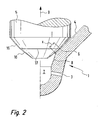
- FIG. 2 a second embodiment of an injection nozzle 1 according to the invention is shown.
- the cooperating with the nozzle needle seat 4 end of the nozzle needle 5 is designed as a double cone.
- a first cone 15 is followed by a second cone 16.
- the cone angle of the first cone 15 is smaller than the cone angle of the nozzle needle seat 4 and the cone angle of the second cone 16 is greater than the cone angle of the nozzle needle seat 4.
- this causes the Contact zone 6 between the nozzle needle 5 and nozzle needle seat 4 is where the first cone 15 merges into the second cone 16.
- This transitional area is in FIG. 2 has been provided with the reference numeral 17.
- the length x of the frusto-conical annular gap between the nozzle needle 5 and the nozzle needle seat 4 in this embodiment becomes smaller than the first embodiment (see right side of FIG. 1 ) again shortened.
- the influence of the flow resistance of the annular gap between the nozzle needle 5 and nozzle needle seat 4 drops in the partial stroke of the injection nozzle 1 again on the dispersion of the flow resistance, which the performance of an internal combustion engine, which is aligned with the injection nozzles 1 according to the second embodiment, again.
- the transition cone 8 can be easily and inexpensively manufactured by grinding, countersinking, embossing or another machining or cutting machining process become.
- the nozzle needle 5 will incorporate something in the nozzle needle seat 4 in the region of the contact zone 6 by plastically deforming the nozzle needle seat 4 and removing and / or displacing some material from the nozzle needle seat 4.
- the length "x" of the annular gap between the nozzle needle 5 and nozzle needle seat 4 shortens with increasing operating time of the injection nozzle 1 according to the invention.
- FIG. 3 the hydraulic diameter 10 of a blind hole injection nozzle 1 is applied qualitatively over the nozzle needle lift 9.
- the hydraulic diameter 10 is a size by means of which any flow-through cross-sections are made comparable in terms of their flow resistance.
- the reference value is the flow resistance of a pipe with a circular cross-section. A cross section with a large hydraulic diameter has a low flow resistance and vice versa.
- the nozzle needle stroke 9 was divided into two areas.
- a first range extends from zero to "a”
- the second range hereinafter referred to as partial lift range, extends from “a” to "b”.
- At “c” is the full nozzle needle stroke reached.
- a very narrow gap results through which the pressurized fuel can flow into the blind hole 2 in the case of a very small nozzle needle lift 9 in the region of the contact zone 6 .
- This very narrow gap determines the flow resistance of the injection nozzle 1 and the needle stability in the nozzle body; d. H. the prevention of fluttering of the needle; decisive and thus determines the hydraulic diameter 10. Since the flow resistance of this very narrow gap is large, the hydraulic diameter 10 of the injection nozzle 1 is very small in the case of a very small nozzle needle stroke 9.
- the injection hole 3 of the injection nozzle 1 is decisive for the hydraulic Diameter of the injection nozzle 1.
- the effects of different surface roughnesses in the region of the frustoconical annular gap between the nozzle needle seat 4 and the nozzle needle 5 on the hydraulic diameter in the partial stroke range were indicated by the characteristic curves 11, 12 and 13.
- the dashed line curve 12 represents an injection nozzle 1 in which the annular gap in comparison to the characteristic curve 11 has a larger hydraulic diameter and consequently has lower throttle losses.
- the dashed line curve 13 shows the effects of an annular gap, which relative to the characteristic 11 in FIG. 3 has a stronger throttle effect.
- the map of the internal combustion engine and the associated injection system is determined by means of one or more selected reference injectors 1 by measurements.
- the maps determined in this way are based on all identical injection systems.
- the characteristic curve 11 is a measured characteristic curve of a reference injection nozzle, and that this characteristic curve 11 is stored in the control unit of the injection system. It is further assumed that two injection nozzles 1 removed from the series production have the characteristic curves 12 and 13. If the injection nozzles 1 interact with the characteristic curves 12 and 13 with a control unit in which the characteristic 11 is stored, the actual injection quantity in the partial stroke range does not coincide with the optimum injection quantity measured according to the characteristic 11 in the test specimens, so that the power and / or the emission behavior of the internal combustion engine deteriorates becomes.
- the shortening of the characteristic curves 11, 12 and 13 is reduced by the inventive shortening of the length "x" of the frustoconical annular gap in the partial stroke by the transition cone 8.
- the correspondence between the characteristic curve 11 stored in the control unit and the characteristic curves 12 and 13 of two injection nozzles taken from the series production is markedly improved.
- the match can for example be improved by a factor of 2 to 3.
- the actual amount of fuel injected corresponds exactly to the injection quantity specified by the control unit and the fuel consumption and emission behavior of the internal combustion engine is optimal.
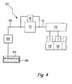
- the fuel injection system 102 includes a fuel tank 104 from which fuel 106 is conveyed by an electric or mechanical fuel pump 108. Via a low-pressure fuel line 110, the fuel 106 is conveyed to a high-pressure fuel pump 111. Of the high-pressure fuel pump 111, the fuel 106 passes through a high-pressure fuel line 112 to a common rail 114. On the common rail 114 a plurality of fuel injection nozzles 1 according to the invention are connected, which inject the fuel 106 directly into combustion chambers 118 of an internal combustion engine, not shown.
- the erfindunstrae injector can be used in a variety of injection system 102 and in various designs. Your benefits are particularly important High-pressure fuel injection systems with injection pressures> 1600 bar to day.
Claims (11)
- Buse d'injection (1) pour moteurs à combustion interne, comprenant un trou borgne (2) présentant au moins un orifice d'injection (3), et un siège d'aiguille de buse (4) rattaché au trou borgne (2), avec entre le trou borgne (3) et le siège d'aiguille de buse (4), un cône de transition (8), le siège d'aiguille de buse (4) et le cône de transition (8) formant une arête de coupe,
caractérisée en ce qu'
une distance entre l'arête de coupe et le fond du trou borgne (2) est inférieure à une distance entre la zone de contact (6) du siège d'aiguille de buse (4) avec une aiguille de buse (5) d'une part, et le fond du trou borgne (2) d'autre part, et une extrémité d'une aiguille de buse (5) coopérant avec le siège d'aiguille de buse (4) est configurée en forme de tronc de cône. - Buse d'injection (1) selon la revendication 1,
caractérisée en ce qu'
un angle de cône () du cône de transition (8) correspond approximativement à la bissectrice entre le trou borgne (2) et le siège d'aiguille de buse (4). - Buse d'injection (1) selon la revendication 1 ou 2,
caractérisée en ce que
le trou borgne (2) est conique. - Buse d'injection (1) selon la revendication 1 ou 2,
caractérisée en ce que
le trou borgne (2) est cylindrique. - Buse d'injection (1) selon l'une des revendications précédentes,
caractérisée en ce que
le siège d'aiguille de buse (4) est en forme de tronc de cône. - Buse d'injection (1) selon la revendication 5,
caractérisée en ce que
l'angle de cône du siège d'aiguille de buse (4) est égal à 60°. - Buse d'injection (1) selon l'une des revendications précédentes,
caractérisée en ce que
l'extrémité de l'aiguille de buse (5) coopérant avec le siège d'aiguille de buse (4) est en forme de double tronc de cône. - Buse d'injection (1) selon l'une des revendications précédentes,
caractérisée en ce qu'
un angle de cône d'une aiguille de buse (5), jusqu'à un certain degré, de préférence de 15 à 30 minutes angulaires, est supérieur à l'angle de cône du siège d'aiguille de buse (4). - Buse d'injection (1) selon l'une des revendications précédentes,
caractérisée en ce que
le trou borgne (2) est un mini-trou borgne ou un micro-trou borgne. - Buse d'injection (1) selon l'une des revendications précédentes,
caractérisée en ce que
la transition entre l'orifice d'injection (3) et le trou borgne (2) est arrondie. - Buse d'injection (1) selon l'une des revendications précédentes,
caractérisée en ce que
l'au moins un orifice d'injection (3) est disposé dans le siège d'aiguille de buse (4) ou dans le cône de transition (8).
Applications Claiming Priority (3)
| Application Number | Priority Date | Filing Date | Title |
|---|---|---|---|
| DE10307873 | 2003-02-25 | ||
| DE2003107873 DE10307873A1 (de) | 2003-02-25 | 2003-02-25 | Sackloch- und Sitzloch-Einspritzdüse für eine Brennkraftmaschine mit einem Übergangskegel zwischen Sackloch und Düsennadelsitz |
| PCT/DE2003/002790 WO2004076850A1 (fr) | 2003-02-25 | 2003-08-21 | Buse d'injection a trou borgne et a siege perfore destinee a un moteur a combustion interne et presentant un cone de transition entre le trou borgne et le siege d'aiguille de buse |
Publications (2)
| Publication Number | Publication Date |
|---|---|
| EP1599670A1 EP1599670A1 (fr) | 2005-11-30 |
| EP1599670B1 true EP1599670B1 (fr) | 2008-03-19 |
Family
ID=32797715
Family Applications (1)
| Application Number | Title | Priority Date | Filing Date |
|---|---|---|---|
| EP03816024A Expired - Lifetime EP1599670B1 (fr) | 2003-02-25 | 2003-08-21 | Buse d'injection a trou borgne et a siege perfore destinee a un moteur a combustion interne et presentant un cone de transition entre le trou borgne et le siege d'aiguille de buse |
Country Status (3)
| Country | Link |
|---|---|
| EP (1) | EP1599670B1 (fr) |
| DE (2) | DE10307873A1 (fr) |
| WO (1) | WO2004076850A1 (fr) |
Cited By (3)
| Publication number | Priority date | Publication date | Assignee | Title |
|---|---|---|---|---|
| CN105492757A (zh) * | 2013-08-30 | 2016-04-13 | 罗伯特·博世有限公司 | 燃料喷射器 |
| EP3073107A1 (fr) | 2015-03-25 | 2016-09-28 | Robert Bosch Gmbh | Soupape d'injection de carburant pour moteurs a combustion interne et utilisation d'une soupape d'injection de carburant |
| WO2016150591A1 (fr) | 2015-03-25 | 2016-09-29 | Robert Bosch Gmbh | Soupape d'injection de carburant pour des moteurs à combustion interne |
Families Citing this family (4)
| Publication number | Priority date | Publication date | Assignee | Title |
|---|---|---|---|---|
| DE102004063166A1 (de) * | 2004-12-29 | 2006-07-13 | Robert Bosch Gmbh | Dosierungsvorrichtung für Flüssigkeiten |
| JP2007224746A (ja) * | 2006-02-21 | 2007-09-06 | Isuzu Motors Ltd | インジェクタノズル |
| DE102010026687A1 (de) * | 2010-07-09 | 2012-01-12 | Continental Automotive Gmbh | Düsenkörper für einen Kraftstoffinjektor und Herstellungsverfahren für einen Düsenkörper |
| US9903329B2 (en) | 2012-04-16 | 2018-02-27 | Cummins Intellectual Property, Inc. | Fuel injector |
Family Cites Families (7)
| Publication number | Priority date | Publication date | Assignee | Title |
|---|---|---|---|---|
| DE932209C (de) * | 1952-04-13 | 1955-08-25 | Bosch Gmbh Robert | Kraftstoffeinspritzventil |
| DE3014958A1 (de) * | 1980-04-18 | 1981-10-29 | Robert Bosch Gmbh, 7000 Stuttgart | Kraftstoff-einspritzduese, insbesondere lochduese, fuer brennkraftmaschinen |
| EP0283154A1 (fr) * | 1987-03-14 | 1988-09-21 | LUCAS INDUSTRIES public limited company | Injecteur de combustible |
| JPH10281041A (ja) * | 1997-04-01 | 1998-10-20 | Mitsubishi Heavy Ind Ltd | 燃料噴射弁 |
| DE19820513A1 (de) * | 1998-05-08 | 1999-11-11 | Mtu Friedrichshafen Gmbh | Kraftstoffeinspritzdüse für eine Brennkraftmaschine |
| JP2000320429A (ja) * | 1999-05-13 | 2000-11-21 | Denso Corp | 燃料噴射ノズル |
| DE19931761A1 (de) * | 1999-07-08 | 2001-01-18 | Bosch Gmbh Robert | Sackloch-Einspritzdüse für Brennkraftmaschinen mit abgerundetem Übergang zwischen Sackloch und Düsennadelsitz |
-
2003
- 2003-02-25 DE DE2003107873 patent/DE10307873A1/de not_active Withdrawn
- 2003-08-21 WO PCT/DE2003/002790 patent/WO2004076850A1/fr active IP Right Grant
- 2003-08-21 DE DE50309436T patent/DE50309436D1/de not_active Expired - Lifetime
- 2003-08-21 EP EP03816024A patent/EP1599670B1/fr not_active Expired - Lifetime
Cited By (6)
| Publication number | Priority date | Publication date | Assignee | Title |
|---|---|---|---|---|
| CN105492757A (zh) * | 2013-08-30 | 2016-04-13 | 罗伯特·博世有限公司 | 燃料喷射器 |
| CN105492757B (zh) * | 2013-08-30 | 2018-10-23 | 罗伯特·博世有限公司 | 燃料喷射器 |
| EP3073107A1 (fr) | 2015-03-25 | 2016-09-28 | Robert Bosch Gmbh | Soupape d'injection de carburant pour moteurs a combustion interne et utilisation d'une soupape d'injection de carburant |
| WO2016150591A1 (fr) | 2015-03-25 | 2016-09-29 | Robert Bosch Gmbh | Soupape d'injection de carburant pour des moteurs à combustion interne |
| DE102015205423A1 (de) | 2015-03-25 | 2016-09-29 | Robert Bosch Gmbh | Kraftstoffeinspritzventil für Brennkraftmaschinen und Verwendung des Kraftstoffeinspritzventils |
| DE102015205416A1 (de) | 2015-03-25 | 2016-09-29 | Robert Bosch Gmbh | Kraftstoffeinspritzventil für Brennkraftmaschinen |
Also Published As
| Publication number | Publication date |
|---|---|
| EP1599670A1 (fr) | 2005-11-30 |
| DE10307873A1 (de) | 2004-09-02 |
| WO2004076850A1 (fr) | 2004-09-10 |
| DE50309436D1 (de) | 2008-04-30 |
Similar Documents
| Publication | Publication Date | Title |
|---|---|---|
| EP2250365B1 (fr) | Élément distributeur de carburant | |
| EP1129287B1 (fr) | Buse d'injection pour moteurs a combustion interne avec pointeau pourvu d'une rainure annulaire | |
| EP1599670B1 (fr) | Buse d'injection a trou borgne et a siege perfore destinee a un moteur a combustion interne et presentant un cone de transition entre le trou borgne et le siege d'aiguille de buse | |
| EP2297447B1 (fr) | Pompe à haute pression | |
| DE3151020C2 (fr) | ||
| EP1357283A2 (fr) | Dispositif d'injection de carburant pour un moteur à combustion interne | |
| EP1537324B1 (fr) | Dispositif pour ventiler une unite d'acheminement | |
| EP1574701A1 (fr) | Injecteur de common rail | |
| DE19843616A1 (de) | Kraftstoffeinspritzdüse | |
| EP1312796B1 (fr) | Soupape d'injection de combustible | |
| EP1296054A1 (fr) | Injecteur pour un moteur à combustion | |
| WO2002079636A1 (fr) | Soupape d'injection | |
| EP1157208B1 (fr) | Buse d'injection a trou borgne pour moteurs a combustion interne a passage arrondi entre le trou borgne et le siege de l'aiguille d'injecteur | |
| DE10346075B4 (de) | Verfahren zur Herstellung eines Kraftstoffeinspritzventils und nach diesem Verfahren hergestelltes Kraftstoffeinspritzventil | |
| EP1518050B1 (fr) | Injecteur pour un systeme d'injection | |
| DE19843912B4 (de) | Kraftstoffeinspritzdüse | |
| WO2017220240A1 (fr) | Pompe à carburant haute pression comprenant un carter et procédé d'usinage de conduits d'un carter d'une pompe à carburant haute pression | |
| EP1759115B1 (fr) | Pompe a haute pression pour un dispositif d'injection de carburant d'un moteur a combustion interne | |
| EP1527272B1 (fr) | Injecteur de carburant comprenant une zone de raccordement resistant a haute pression | |
| DE102004022428A1 (de) | Einspritzventil für Brennkraftmaschinen | |
| DE10346242B4 (de) | Injektorkörper für einen Common Rail Injektor | |
| EP1771655B1 (fr) | Ecrou de serrage | |
| WO2006048371A1 (fr) | Dispositif d'injection de carburant pour moteur a combustion interne | |
| EP2914839A1 (fr) | Ensemble buse d'un injecteur de carburant et injecteur de carburant | |
| DE102010030396A1 (de) | Kraftstoffinjektor |
Legal Events
| Date | Code | Title | Description |
|---|---|---|---|
| PUAI | Public reference made under article 153(3) epc to a published international application that has entered the european phase |
Free format text: ORIGINAL CODE: 0009012 |
|
| 17P | Request for examination filed |
Effective date: 20050926 |
|
| AK | Designated contracting states |
Kind code of ref document: A1 Designated state(s): AT BE BG CH CY CZ DE DK EE ES FI FR GB GR HU IE IT LI LU MC NL PT RO SE SI SK TR |
|
| RBV | Designated contracting states (corrected) |
Designated state(s): DE FR |
|
| 17Q | First examination report despatched |
Effective date: 20051223 |
|
| GRAP | Despatch of communication of intention to grant a patent |
Free format text: ORIGINAL CODE: EPIDOSNIGR1 |
|
| GRAS | Grant fee paid |
Free format text: ORIGINAL CODE: EPIDOSNIGR3 |
|
| GRAA | (expected) grant |
Free format text: ORIGINAL CODE: 0009210 |
|
| AK | Designated contracting states |
Kind code of ref document: B1 Designated state(s): DE FR |
|
| REF | Corresponds to: |
Ref document number: 50309436 Country of ref document: DE Date of ref document: 20080430 Kind code of ref document: P |
|
| ET | Fr: translation filed | ||
| PLBE | No opposition filed within time limit |
Free format text: ORIGINAL CODE: 0009261 |
|
| STAA | Information on the status of an ep patent application or granted ep patent |
Free format text: STATUS: NO OPPOSITION FILED WITHIN TIME LIMIT |
|
| 26N | No opposition filed |
Effective date: 20081222 |
|
| REG | Reference to a national code |
Ref country code: FR Ref legal event code: PLFP Year of fee payment: 14 |
|
| REG | Reference to a national code |
Ref country code: FR Ref legal event code: PLFP Year of fee payment: 15 |
|
| REG | Reference to a national code |
Ref country code: FR Ref legal event code: PLFP Year of fee payment: 16 |
|
| PGFP | Annual fee paid to national office [announced via postgrant information from national office to epo] |
Ref country code: FR Payment date: 20220822 Year of fee payment: 20 |
|
| PGFP | Annual fee paid to national office [announced via postgrant information from national office to epo] |
Ref country code: DE Payment date: 20221025 Year of fee payment: 20 |
|
| REG | Reference to a national code |
Ref country code: DE Ref legal event code: R071 Ref document number: 50309436 Country of ref document: DE |