EP0933165B1 - A spindle for an abrasive band strip and an apparatus for replacing it with a new one - Google Patents
A spindle for an abrasive band strip and an apparatus for replacing it with a new one Download PDFInfo
- Publication number
- EP0933165B1 EP0933165B1 EP19990660014 EP99660014A EP0933165B1 EP 0933165 B1 EP0933165 B1 EP 0933165B1 EP 19990660014 EP19990660014 EP 19990660014 EP 99660014 A EP99660014 A EP 99660014A EP 0933165 B1 EP0933165 B1 EP 0933165B1
- Authority
- EP
- European Patent Office
- Prior art keywords
- spindle
- abrasive band
- folding
- folding table
- slot
- Prior art date
- Legal status (The legal status is an assumption and is not a legal conclusion. Google has not performed a legal analysis and makes no representation as to the accuracy of the status listed.)
- Expired - Lifetime
Links
Images


Classifications
-
- B—PERFORMING OPERATIONS; TRANSPORTING
- B24—GRINDING; POLISHING
- B24B—MACHINES, DEVICES, OR PROCESSES FOR GRINDING OR POLISHING; DRESSING OR CONDITIONING OF ABRADING SURFACES; FEEDING OF GRINDING, POLISHING, OR LAPPING AGENTS
- B24B45/00—Means for securing grinding wheels on rotary arbors
-
- B—PERFORMING OPERATIONS; TRANSPORTING
- B24—GRINDING; POLISHING
- B24B—MACHINES, DEVICES, OR PROCESSES FOR GRINDING OR POLISHING; DRESSING OR CONDITIONING OF ABRADING SURFACES; FEEDING OF GRINDING, POLISHING, OR LAPPING AGENTS
- B24B33/00—Honing machines or devices; Accessories therefor
- B24B33/08—Honing tools
Definitions
- This invention relates to an apparatus to double-fold the abrasive band, cut to desired lenght, the abrasive surface outwards, and to insert this transversally to the slot of said spindle, replacing the used abrasive band taken away from the slot.
- the spindles of said type with axial slots in the end to receive a double-folded abrasive band, the abrasive surface turned outwards, and it has been possible to fix the spindle e.g. to the socket of a boring machine enabling it to hone holes, orifices and other narrow and inconvenient spots.
- the length of the abrasive band is selected in accordance with the size of the hole, orifice or cavity to be honed.
- the abrasive band will wear relatively fast and then it has to be replaced, e.g. by removing the spindle from its socket and by replacing it with another having an unused abrasive band.
- the used abrasive band has to be removed from the removed spindle and an unused abrasive band has to be first folded and then inserted to the slot. Previously, this has been done manually, and the aim of the present invention is to automate the replacement of the abrasive band in the spindles of said type.
- a spindle in accordance with this description enables the replacement of the abrasive band being automated using an apparatus comprising a folding table to receive the abrasive band, two folding surfaces to be brought against each other along the folding table, the folding surfaces comprising parallel grooves directed away from the folding table, means to move at least one of the folding surfaces towards the other one on the folding table so that the groove pairs against each other on the folding surfaces form recesses where the spindle can be pushed when its slot is at the same level with the folding levels being against each other, and a guiding surface on the incoming path of the spindle to make the spindle roll or rotate around its longitudinal axle as its curved and advantageously round surface moves along the guiding surface, and to stop the rotating movement when the level surface in the advantageously round surface, with a curved cross-section, meets the guiding surface, whereby said guiding level continues onto the folding table directed so that the slot of the spindle is at the same level with the folding surfaces, these then pressing the double-folded abrasive
- Fig. 3 shows that on the periphery of the lower counter-roller 5 there is a low ridge 8, positioned centrally and parallel with the roller periphery, with a spike-like cross-section, by means which a crease line is formed on the smooth lower surface of the abrasive band, on the longitudinal central line of the abrasive band 2.
- the cutter 12 is equipped with a piston 13 to produce the upward directed impact of the cutter 12 so that its uppermost blade is moving like a guillotine along the end surface of the cutting guide 10 and across the opening 11, cutting the abrasive band 2, fed through the opening, to an abrasive band 2' of desired length and to be left on the folding table 14.
- a new section of the blade can be used after the wearing down of the preceding one, and in this way it is possible to significantly increase the usable life of the cutter and the intervals of replacement.
- the folding surfaces 15 and 17 comprise vertical grooves 18, with cross-sections essentially formed like semi-circles, at such a mutual distance from each other that they form, as pairs, when the folding surfaces 15 and 17 have been pressed together, recesses with circular cross-sections, as the diameter of which the double-folded abrasive band 2' between the folding surfaces 15 and 17 is functioning.
- the grooves 18 extend to the height of the folding surfaces 15 and 17 but, at their lower ends, they are advantageously bevelled so that the folding levels 15 and 17 do not press the abrasive band 2' between them against the folding table 14.
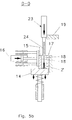
- Fig. 5b shows the folding levels 15 and 17 pressed together, whereby the abrasive band 2' between them has been pressed double-folded between them and the vertical grooves 18 extending to the entire height of the folding surfaces 15 and 17 forming pairs of vertical recesses with circular cross-sections.
- the folding table is advantageously provided with a spring so that the double-folded abrasive band 2' is pushed sufficiently deep in the slot 24, as shown in more detail in Fig. 5c.
- the folding surface 15 is moved away from the fixed folding surface 17, whereby the spindle 23 in the slot 24 of which the double-folded abrasive band 2' is, with its abrasive surfaces facing outwards, can be removed, as shown in more detail in Fig. 5d.
- the rounded surfaces 26 of the spindle 23 are advantageously roughened so that when the spindle is led along the side of the guide 19 it rotates freely round its axle under the spring load 27, whereby the spindle 23 can be rolled round its longitudinal axle until one of the level surfaces 25 comes against the side surface of the guide 19, stopping the rotating movement of the spindle by itself, and then it slides further to the desired opening above the folding surfaces 15 and 17, still pressed together, the slot 24 being then at the same level with the double-folded abrasive band 2' between the folding surfaces 15 and 17.
- the used abrasive band in the slot 24 of the spindle 23 can be removed from the slot by lifting the spindle 23 axially upwards, whereby the gap 22 prevents the used abrasive band from moving together with the spindle 23, after which the spindle 23 can be moved further along the guide 19 to receive the new abrasive band 2' to be installed in it.
- the present invention can be modified within a very large range within the scope of the appended Claims.
- the level surface or surfaces directing the slot of the spindle can be situated in the robot moving the spindle, for instance in its socket where the spindle is fixed, provided that the spindle can be fixed into the socket only in a determined position in relation to the level surface or surfaces in the socket, and that the socket is freely rotating. It is also evident that any details of the apparatus in accordance with the invention can be modified without deviating from the scope of the Claims.
Applications Claiming Priority (2)
| Application Number | Priority Date | Filing Date | Title |
|---|---|---|---|
| FI980224A FI103648B (fi) | 1998-02-02 | 1998-02-02 | Kara hiomanauhaliuskaa varten ja laite hiomanauhaliuskan uusimiseksi |
| FI980224 | 1998-02-02 |
Publications (3)
| Publication Number | Publication Date |
|---|---|
| EP0933165A2 EP0933165A2 (en) | 1999-08-04 |
| EP0933165A3 EP0933165A3 (en) | 2002-08-07 |
| EP0933165B1 true EP0933165B1 (en) | 2004-05-12 |
Family
ID=8550652
Family Applications (1)
| Application Number | Title | Priority Date | Filing Date |
|---|---|---|---|
| EP19990660014 Expired - Lifetime EP0933165B1 (en) | 1998-02-02 | 1999-01-26 | A spindle for an abrasive band strip and an apparatus for replacing it with a new one |
Country Status (3)
| Country | Link |
|---|---|
| EP (1) | EP0933165B1 (un) |
| DE (1) | DE69917089T2 (un) |
| FI (1) | FI103648B (un) |
Families Citing this family (2)
| Publication number | Priority date | Publication date | Assignee | Title |
|---|---|---|---|---|
| DE102021104526B4 (de) | 2021-02-25 | 2022-09-08 | APEX Automatisierungs- & Präzisionstechnik GmbH | Werkzeug mit einem Schleifbandhalter |
| DE102022119483A1 (de) | 2022-08-03 | 2024-02-08 | APEX Automatisierungs- & Präzisionstechnik GmbH | Verfahren sowie Anlage zum Entgraten und/oder Polieren von Werkstücken |
Family Cites Families (4)
| Publication number | Priority date | Publication date | Assignee | Title |
|---|---|---|---|---|
| FR1039994A (fr) * | 1951-07-19 | 1953-10-12 | Ponceuse | |
| US2749680A (en) * | 1954-06-08 | 1956-06-12 | Palley Zoltan O St | Abrading tool |
| US3877185A (en) * | 1974-06-03 | 1975-04-15 | Edmund F Wells | Abrading tool |
| US4536994A (en) * | 1983-09-07 | 1985-08-27 | Krebs William T | Curved surface sanding device |
-
1998
- 1998-02-02 FI FI980224A patent/FI103648B/fi not_active IP Right Cessation
-
1999
- 1999-01-26 DE DE69917089T patent/DE69917089T2/de not_active Expired - Lifetime
- 1999-01-26 EP EP19990660014 patent/EP0933165B1/en not_active Expired - Lifetime
Also Published As
| Publication number | Publication date |
|---|---|
| DE69917089T2 (de) | 2005-05-12 |
| FI103648B1 (fi) | 1999-08-13 |
| EP0933165A2 (en) | 1999-08-04 |
| FI103648B (fi) | 1999-08-13 |
| DE69917089D1 (de) | 2004-06-17 |
| EP0933165A3 (en) | 2002-08-07 |
| FI980224A0 (fi) | 1998-02-02 |
Similar Documents
| Publication | Publication Date | Title |
|---|---|---|
| US7827891B1 (en) | Device for cutting a work piece in a transport line | |
| DE2902343A1 (de) | Eine kreisumlaufbewegung ausfuehrende saege | |
| US5431597A (en) | Skate blade edge resurfacer | |
| US3877353A (en) | Stripping device | |
| EP0641274B1 (en) | A machine for cutting a paper web into sheets with simultaneous cutting of a transverse strip | |
| CN111606101B (zh) | 一种纺织布料切割收卷装置 | |
| EP0933165B1 (en) | A spindle for an abrasive band strip and an apparatus for replacing it with a new one | |
| US5311800A (en) | Apparatus for severing (collar) blanks from a web of material | |
| CN107243932B (zh) | 膜分切调整装置 | |
| WO2010007171A1 (de) | Schärfmaschine für schneidklingen | |
| CN112916571B (zh) | 一种刷条回收设备 | |
| CN214350024U (zh) | 一种钢带裁切机构 | |
| CN207616326U (zh) | 一种钢带导向装置 | |
| US3077148A (en) | Filter pleating machine | |
| KR101316220B1 (ko) | 스크랩 처리장치 | |
| CN113942867B (zh) | 一种能够自动裁切的分纸机 | |
| EP2095917B1 (en) | Tissue paper cutting mechanism having upper knife with variable spiral curve angle and upper knife structure therefor | |
| CN112429574A (zh) | 一种消毒布定长裁断机 | |
| CN112623846A (zh) | 一种消毒布裁断机及其裁切机构 | |
| CN210553556U (zh) | 一种印花机的裁切装置 | |
| CN208617067U (zh) | 一种复卷机压纸辊自动平衡装置 | |
| EP1174229A2 (de) | Längsteilschere | |
| CN117021788B (zh) | 一种旋转切刀结构及便携式打印设备 | |
| CN108515779A (zh) | 一种使用圆刀的标签打印机切刀装置 | |
| JPS5841120Y2 (ja) | ロ−タリ−カツタ− |
Legal Events
| Date | Code | Title | Description |
|---|---|---|---|
| PUAI | Public reference made under article 153(3) epc to a published international application that has entered the european phase |
Free format text: ORIGINAL CODE: 0009012 |
|
| AK | Designated contracting states |
Kind code of ref document: A2 Designated state(s): AT BE CH CY DE DK ES FI FR GB GR IE IT LI LU MC NL PT SE |
|
| AX | Request for extension of the european patent |
Free format text: AL;LT;LV;MK;RO;SI |
|
| PUAL | Search report despatched |
Free format text: ORIGINAL CODE: 0009013 |
|
| AK | Designated contracting states |
Kind code of ref document: A3 Designated state(s): AT BE CH CY DE DK ES FI FR GB GR IE IT LI LU MC NL PT SE |
|
| AX | Request for extension of the european patent |
Free format text: AL;LT;LV;MK;RO;SI |
|
| RIC1 | Information provided on ipc code assigned before grant |
Free format text: 7B 24B 33/08 A, 7B 24B 45/00 B, 7B 24D 9/04 B |
|
| 17P | Request for examination filed |
Effective date: 20030123 |
|
| AKX | Designation fees paid |
Designated state(s): DE FR GB SE |
|
| 17Q | First examination report despatched |
Effective date: 20030613 |
|
| GRAP | Despatch of communication of intention to grant a patent |
Free format text: ORIGINAL CODE: EPIDOSNIGR1 |
|
| GRAS | Grant fee paid |
Free format text: ORIGINAL CODE: EPIDOSNIGR3 |
|
| GRAA | (expected) grant |
Free format text: ORIGINAL CODE: 0009210 |
|
| AK | Designated contracting states |
Kind code of ref document: B1 Designated state(s): DE FR GB SE |
|
| RAP1 | Party data changed (applicant data changed or rights of an application transferred) |
Owner name: PULMEK OY |
|
| REG | Reference to a national code |
Ref country code: GB Ref legal event code: FG4D |
|
| REG | Reference to a national code |
Ref country code: IE Ref legal event code: FG4D |
|
| REF | Corresponds to: |
Ref document number: 69917089 Country of ref document: DE Date of ref document: 20040617 Kind code of ref document: P |
|
| REG | Reference to a national code |
Ref country code: SE Ref legal event code: TRGR |
|
| ET | Fr: translation filed | ||
| PLBE | No opposition filed within time limit |
Free format text: ORIGINAL CODE: 0009261 |
|
| STAA | Information on the status of an ep patent application or granted ep patent |
Free format text: STATUS: NO OPPOSITION FILED WITHIN TIME LIMIT |
|
| 26N | No opposition filed |
Effective date: 20050215 |
|
| REG | Reference to a national code |
Ref country code: FR Ref legal event code: PLFP Year of fee payment: 18 |
|
| REG | Reference to a national code |
Ref country code: FR Ref legal event code: PLFP Year of fee payment: 19 |
|
| REG | Reference to a national code |
Ref country code: FR Ref legal event code: PLFP Year of fee payment: 20 |
|
| PGFP | Annual fee paid to national office [announced via postgrant information from national office to epo] |
Ref country code: GB Payment date: 20180116 Year of fee payment: 20 Ref country code: DE Payment date: 20180116 Year of fee payment: 20 |
|
| PGFP | Annual fee paid to national office [announced via postgrant information from national office to epo] |
Ref country code: FR Payment date: 20180116 Year of fee payment: 20 Ref country code: SE Payment date: 20180115 Year of fee payment: 20 |
|
| REG | Reference to a national code |
Ref country code: DE Ref legal event code: R071 Ref document number: 69917089 Country of ref document: DE |
|
| REG | Reference to a national code |
Ref country code: GB Ref legal event code: PE20 Expiry date: 20190125 |
|
| PG25 | Lapsed in a contracting state [announced via postgrant information from national office to epo] |
Ref country code: GB Free format text: LAPSE BECAUSE OF EXPIRATION OF PROTECTION Effective date: 20190125 |