EP0913989A2 - Methods and apparatus for visually identifying an area on a photograph or image where digital data is stored - Google Patents
Methods and apparatus for visually identifying an area on a photograph or image where digital data is stored Download PDFInfo
- Publication number
- EP0913989A2 EP0913989A2 EP98203451A EP98203451A EP0913989A2 EP 0913989 A2 EP0913989 A2 EP 0913989A2 EP 98203451 A EP98203451 A EP 98203451A EP 98203451 A EP98203451 A EP 98203451A EP 0913989 A2 EP0913989 A2 EP 0913989A2
- Authority
- EP
- European Patent Office
- Prior art keywords
- image
- data
- printed
- audio data
- visible
- Prior art date
- Legal status (The legal status is an assumption and is not a legal conclusion. Google has not performed a legal analysis and makes no representation as to the accuracy of the status listed.)
- Granted
Links
- 238000000034 method Methods 0.000 title claims abstract description 38
- 230000003287 optical effect Effects 0.000 claims abstract description 42
- 230000000007 visual effect Effects 0.000 claims abstract description 13
- 239000003086 colorant Substances 0.000 claims abstract description 12
- 238000012545 processing Methods 0.000 claims description 40
- 230000000694 effects Effects 0.000 claims description 7
- 239000000758 substrate Substances 0.000 claims description 4
- 230000002093 peripheral effect Effects 0.000 claims 1
- 230000001066 destructive effect Effects 0.000 abstract 1
- 238000009877 rendering Methods 0.000 description 8
- 230000008569 process Effects 0.000 description 3
- 230000005236 sound signal Effects 0.000 description 2
- 229910052693 Europium Inorganic materials 0.000 description 1
- 229910052688 Gadolinium Inorganic materials 0.000 description 1
- LYRYFSZCOJEXFH-UHFFFAOYSA-L [Tb+2].[O-]C(=O)C1=CC=CC=N1.[O-]C(=O)C1=CC=CC=N1 Chemical class [Tb+2].[O-]C(=O)C1=CC=CC=N1.[O-]C(=O)C1=CC=CC=N1 LYRYFSZCOJEXFH-UHFFFAOYSA-L 0.000 description 1
- 238000004458 analytical method Methods 0.000 description 1
- 239000003795 chemical substances by application Substances 0.000 description 1
- 238000007405 data analysis Methods 0.000 description 1
- 230000003247 decreasing effect Effects 0.000 description 1
- -1 e.g Substances 0.000 description 1
- OGPBJKLSAFTDLK-UHFFFAOYSA-N europium atom Chemical compound [Eu] OGPBJKLSAFTDLK-UHFFFAOYSA-N 0.000 description 1
- 230000006870 function Effects 0.000 description 1
- UIWYJDYFSGRHKR-UHFFFAOYSA-N gadolinium atom Chemical compound [Gd] UIWYJDYFSGRHKR-UHFFFAOYSA-N 0.000 description 1
- 150000002500 ions Chemical class 0.000 description 1
- 229910052747 lanthanoid Inorganic materials 0.000 description 1
- 150000002602 lanthanoids Chemical class 0.000 description 1
- 239000011159 matrix material Substances 0.000 description 1
- 230000004048 modification Effects 0.000 description 1
- 238000012986 modification Methods 0.000 description 1
- 230000007935 neutral effect Effects 0.000 description 1
- 229910052761 rare earth metal Inorganic materials 0.000 description 1
- 230000004044 response Effects 0.000 description 1
- 238000012360 testing method Methods 0.000 description 1
- 238000012546 transfer Methods 0.000 description 1
- 238000001429 visible spectrum Methods 0.000 description 1
Images


Classifications
-
- H—ELECTRICITY
- H04—ELECTRIC COMMUNICATION TECHNIQUE
- H04N—PICTORIAL COMMUNICATION, e.g. TELEVISION
- H04N1/00—Scanning, transmission or reproduction of documents or the like, e.g. facsimile transmission; Details thereof
- H04N1/32—Circuits or arrangements for control or supervision between transmitter and receiver or between image input and image output device, e.g. between a still-image camera and its memory or between a still-image camera and a printer device
- H04N1/32101—Display, printing, storage or transmission of additional information, e.g. ID code, date and time or title
- H04N1/32144—Display, printing, storage or transmission of additional information, e.g. ID code, date and time or title embedded in the image data, i.e. enclosed or integrated in the image, e.g. watermark, super-imposed logo or stamp
-
- H—ELECTRICITY
- H04—ELECTRIC COMMUNICATION TECHNIQUE
- H04N—PICTORIAL COMMUNICATION, e.g. TELEVISION
- H04N2201/00—Indexing scheme relating to scanning, transmission or reproduction of documents or the like, and to details thereof
- H04N2201/32—Circuits or arrangements for control or supervision between transmitter and receiver or between image input and image output device, e.g. between a still-image camera and its memory or between a still-image camera and a printer device
- H04N2201/3201—Display, printing, storage or transmission of additional information, e.g. ID code, date and time or title
- H04N2201/3261—Display, printing, storage or transmission of additional information, e.g. ID code, date and time or title of multimedia information, e.g. a sound signal
-
- H—ELECTRICITY
- H04—ELECTRIC COMMUNICATION TECHNIQUE
- H04N—PICTORIAL COMMUNICATION, e.g. TELEVISION
- H04N2201/00—Indexing scheme relating to scanning, transmission or reproduction of documents or the like, and to details thereof
- H04N2201/32—Circuits or arrangements for control or supervision between transmitter and receiver or between image input and image output device, e.g. between a still-image camera and its memory or between a still-image camera and a printer device
- H04N2201/3201—Display, printing, storage or transmission of additional information, e.g. ID code, date and time or title
- H04N2201/3269—Display, printing, storage or transmission of additional information, e.g. ID code, date and time or title of machine readable codes or marks, e.g. bar codes or glyphs
- H04N2201/327—Display, printing, storage or transmission of additional information, e.g. ID code, date and time or title of machine readable codes or marks, e.g. bar codes or glyphs which are undetectable to the naked eye, e.g. embedded codes
-
- H—ELECTRICITY
- H04—ELECTRIC COMMUNICATION TECHNIQUE
- H04N—PICTORIAL COMMUNICATION, e.g. TELEVISION
- H04N2201/00—Indexing scheme relating to scanning, transmission or reproduction of documents or the like, and to details thereof
- H04N2201/32—Circuits or arrangements for control or supervision between transmitter and receiver or between image input and image output device, e.g. between a still-image camera and its memory or between a still-image camera and a printer device
- H04N2201/3201—Display, printing, storage or transmission of additional information, e.g. ID code, date and time or title
- H04N2201/3271—Printing or stamping
Definitions
- the present invention relates to image and/or photograph generation and, more particularly, to methods and apparatus for generating images and/or photographs with data, for example, audio data, stored on the image and/or photograph.
- audio signals As the price of digital cameras continues to decrease, they are becoming ever more popular. Many digital still cameras have the capability of recording audio signals as well as a digital image. The recording of audio sounds, for example, music at a wedding, is often optional. When audio signals are recorded, they are normally saved within the camera in a digital audio file which is associated with one of the digital image files also stored in the camera. Alternatively, the audio and associated image data may be stored in a single file with the audio and/or video data being identified by a file header.
- audio data may, optionally, be associated therewith.
- Digital audio and image files generated using a digital camera can, and often are, downloaded to a computer system capable of displaying the image files and playing the audio files.
- a computer system capable of displaying the image files and playing the audio files.
- many computer systems include image processing and printing capabilities.
- the present invention resides in a method of generating a printed image, the method characterized by the steps of: processing data representing an image to add visible printed data identification indicia to the image; printing both the image including the visible printed data identification indicia and data to be stored on the printed image, the data to be stored being printed in a manner that results in non-visible machine readable data being included on the printed image.
- the present invention also resides in a printed image, characterized by: a printing substrate; a first layer of ink representing non-visible machine readable data; a layer of visible ink representing an image, the layer of visible ink including visual indicia of the presence of non-visible machine readable data.
- the present invention further resides in an apparatus for processing and printing an image and data, the image processing system characterized by: means for selecting an area within the image to print the data; means for processing the image to add visual indicia indicating the location of the selected area; and printing means for printing both the image including the visual indicia of the location in the image of the selected area and for printing the data in the selected area in a manner that renders it invisible to the human eye.
- audio data is stored, for example, recorded, on a printed image or photograph by printing thereon a series of marks which can be optically detected and converted back into digital data representing, for example, audio information and/or other information, for example, creation date/time information, and so forth
- a bar code type series of lines of varying thickness and/or spacing is used to represent the digital audio data.
- the audio data printed on a photograph in accordance with the present invention does not degrade the visual image quality of the photograph or block out portions of the image
- the audio data is printed using ink which is not visually detectable by the human eye but which can be detected using an optical reader.
- the ink may be slightly noticeable to a human, for example, the printing of the ink used to represent audio data will have a slight effect on the perceived color of portions of photographs over which the audio data is printed, the color or colors of the photograph are adjusted to mask the effect of the ink used to print the audio data.
- the audio data printed on the image or photograph will cover only a small portion of the image or photograph.
- the area on a photograph in which the audio data is printed is referred to herein as the audio data region.
- the audio data region of a photograph be visually identified.
- the identifying of the audio region facilitates subsequent placement of a scanner when reading the stored data and avoids the need for a playback device to scan the entire image to read back the audio data and/or other recorded information.
- the audio data region is identified by subtly modifying the image area of the photograph where the audio data is stored.
- the photographic content in the audio data region is modified to render the region visibly identifiable without destroying the photographic content printed in the audio data region. In one particular implementation, this is done by modifying the optical density of the photograph in the audio data region, for example, to lighten the region by a small amount such as 2-5%.
- the audio data region of a photograph is marked by placing visual markers in a boarder region around the image being printed. In one embodiment this involves placing white boxes in a black boarder to identify the area within the image where the audio data is stored. In another embodiment this involves placing, for example, small black lines, on a white border placed around the photograph.
- the visual indicia of stored audio data added to a photograph in accordance with the present invention make it easy to detect the presence and location of otherwise invisible printed data on a photograph or printed image.
- the present invention is directed to methods and apparatus for generating images and/or photographs with data, for example, audio data, stored on the image and/or photograph.
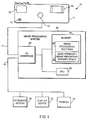
- FIG. 1 illustrates a system, generally indicated by the reference numeral 10, suitable for implementing the method of the present invention.
- the system 10 includes a digital camera 11, an image processing system 20 and input/output devices in the form of a keyboard/mouse 30, a display device 32 and a printer 34.
- the display device 32 may be a color monitor while the printer 34 may be any one of a plurality of known digital printers capable of printing on a substrate, e.g, paper.
- the printer 34 is illustrated as a single printer, it is to be understood that it may comprise one or more printers, for example, with each printer being responsible for printing a different color and one printer being responsible for printing the audio data using what is referred to as "invisible" ink.
- the invisible ink is a color agent that, for the most part; does not absorb or fluoresce light in the human visible spectrum but which is, nevertheless, visible to optical reading machines.
- the ink used to print the audio data is invisible to the naked eye but can be excited by ultra violet light.
- Examples of invisible ink suitable for printing the audio data include ink that is based on organic complexes of, rare earth elements ions (lanthanides), such as: europium, gadolinium and terbium dipicolinates.
- the printer used to apply the invisible ink may be a conventional printer, for example, ink jet, dot matrix, impact, and so forth
- the digital camera 11 includes a flash unit 18, a viewing lens or digital image display area 12, a lens 16 for receiving light from the image to be photographed, and a flash unit 18.
- the digital camera 11 includes a microphone 14 used for recording audio data and first and second switches in the form of buttons 13, 15.
- the first switch 13 is used to control the recording of audio data while the second switch 15 is to control the taking of a picture.
- Audio data which is recorded at the time a picture is taken is stored in an audio data file and associated with a digital image data file.
- the data in the digital image data file represents the picture taken during the audio recording time period.
- the size of each created audio data file is a function of the duration of the audio recording that is made by controlling the switch 13.
- the camera 11 is illustrated as being coupled, via a bus 17, to an input/output (I/O) interface of the image processing system 20.
- I/O input/output
- the bus 17 which may be coupled to the camera 11 via a interface terminal, digital audio and image data files can be downloaded from the camera 11 to the image processing system 20.
- the image processing system 20 of the present invention comprises the I/O interface 22, a central processing unit (CPU) 29 and a memory device 24.
- the I/O interface 22 is responsible for interfacing the various components of the image processing system 20 to the digital camera 11 and the various input/output devices 30, 32, 34 coupled to the image processing system 20.
- the memory 24 includes one or more image processing routines 26 implemented in accordance with the present invention.
- the image processing routines 26 are used to control the CPU 29 when processing data files representing photographs and the audio files associated therewith.
- the memory 24 includes an area 28 used for storing audio and image data received from the camera 11, and for storing data files representing rendered images.
- a rendered image is an image data file which has been processed and formatted for printing.
- a rendered image may comprise a plurality of two dimensional data sets, each data set corresponding to a different color to be rendered. In the case where audio data is to be printed using an invisible ink, the invisible ink is treated as an additional color to be rendered.
- the CPU 29 will generate from the data received, for example, from the camera 11, a separate data file corresponding to each of the colors cyan, magenta, and yellow (assuming use of a CMY color space) or red, green and blue (assuming use of an RGB color space), in addition to a data file corresponding to the invisible ink to be used to print the audio data on the photograph.
- FIG. 2 the steps of an image generation routine 40 implemented in accordance with an exemplary embodiment of the present invention are illustrated.
- the steps illustrated in Fig. 2 may be performed by various components of the system illustrated in Fig. 1 including the digital camera 11 and CPU 29.
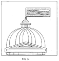
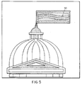
- the routine 40 begins in step 41 wherein the routine is initiated. Operation progresses to steps 42 and 44 wherein audio data and optical data is captured, respectively. Steps 42 and 44 may be performed in parallel by the digital camera 11 illustrated in Fig. 1. Fig. 3 illustrates an image which can be captured and represented as an optical data file, for example, by performing step 44.
- step 45 the optical data captured by the camera 11 and the captured audio data associated with the optical data, if any, are transferred to the memory 24 of the image processing system 20.
- step 46 a determination is made by the image processing system to determine if audio data was received in addition to image processing data. This determination may be made by, for example, examining a header included in a received data file to determine if it includes audio data in addition to optical data or, alternatively, determining if separate optical and audio data files were received from the digital camera 11.
- step 46 if it is determined that optical data was received without associated audio data, operation proceeds to step 48 wherein the received optical image data is rendered in memory, as is known in the art, in the desired color space, for example, CMY or RGB.
- the optical data is processed to form a separate set of two dimensional data for each of the colors to be printed.
- image rendering is performed in step 48, no audio data needs to be printed on the photograph being generated. Accordingly, in step 48 three distinct sets of color printing data, each representing a two dimensional array of color printing information, will be generated.
- step 50 operation proceeds to step 50 wherein the rendered data, in the form of data files corresponding to each color to be printed, are sent from the portion 28 of memory where they are stored prior to being supplied to the printer, for example, via bus 19.
- step 46 If in step 46 it was determined that audio data was received in addition to optical data, for example, the header of a received data file indicates the presence of both audio and optical data in the file or an audio data file was received in addition to an optical data file, operation proceeds from step 46 to step 52.
- the audio data region would be selected to match the smallest multiple of the fixed size units that could accommodate the recording of the audio data.
- the image, represented by the received optical data is analyzed.
- the analysis is performed to detect an image area of the determined size, in the image or photograph to be printed, which has the highest optical density, for example, average optical density. In this manner, a relatively dark region of the image, matching the size of the audio data region, is identified for use in printing of the audio data.
- the ink used to print the audio data is invisible, or mostly invisible, to the human eye. Unfortunately, depending on the ink used for printing the audio data, it may not be completely invisible. In fact, the printing of the dye to store the audio information may slightly impact the perceived color of the underlying image over which the ink is printed. By selecting a dark or relatively dark region of the image being printed to be used as the audio data region, the visible impact of the ink used to print the audio data can be minimized.
- step 56 optical data coordinates, that is, two dimensional data coordinates corresponding to an area of the image to be printed, are assigned for the recording of the audio data on the photograph being printed.
- the spatial requirements for rendering the audio data are specified, for example, a two dimensional point in the photograph being printed is assigned for the position of one of the corners of the audio data region and the overall size and shape of the audio data region on the photograph is specified.
- Fig. 4 there is illustrated the image of Fig. 3 with audio data printed thereon in the form of a bar code 40 located towards the upper right portion of the photograph. While the bar code 40 is printed using visible ink in Fig. 4, in accordance with the present invention it would normally be printed using invisible ink.
- the area, in which the bar code 40 is located is the region which is specified in step 56.
- step 58 the optical data received in step 45 is processed to render the data suitable for outputting, for example, to a printer.
- the received optical image data is rendered in memory in the desired color space, for example, CMY or RGB.
- the optical data for each color to be output is processed to form a separate set of two dimensional data.
- three distinct sets of color data, each representing a two dimensional array of information, for example, printing information, is generated when preparing color image data to be output.
- the rendering process may include adjusting the intensity of the individual colors being rendered in the audio data region to compensate for any effect that printing of the audio data over the color image may have on the colors as they are perceived by a person viewing the photograph. Since the ink used for printing the audio data will normally have been selected prior to performing step 58, its perceived effect, if any, on the colors being printed will normally be known from prior empirical tests and/or general printing knowledge. This makes the modification of the colors in the audio data region to conceal the effect of the printed audio data possible.
- step 60 the sets of optical image data rendered in memory during step 58 are further processed to suitably identify the presence and/or location of audio data in the photograph being printed.
- the presence and location of audio data is identified by reducing the optical density of the image in the audio data region. This involves, for example, decreasing the optical density of each of the 3 rendered color image sets by a subtle but visually identifiable amount, for example, 2-3% in the audio data region defined in step 56. In this manner, the photograph generated will have an easy to identify audio data recording while the integrity of the photograph is maintained since all the image data is displayed and visible.
- Fig. 5 illustrates the image of Fig. 3, after it is printed in accordance with the method of the present invention which involves modifying the optical density of the audio data region 50 to identify the presence and location of printed audio data. Note that in Fig. 5, the printed audio data is invisible. However, the audio data region 50 located in the upper right portion of Fig. 5 is readily identifiable as the light area of the image, that is, the area within the flag.
- the optical data region is identified by adding a neutral density, for example, black, boarder 62 to the photograph with white marks, for example, blocks 60 being located in the boarder 62 to identify the location within the photograph of the audio data region.
- a neutral density for example, black
- boarder 62 to the photograph with white marks, for example, blocks 60 being located in the boarder 62 to identify the location within the photograph of the audio data region.
- a white boarder with relatively small marks 70 is added to the photograph to identify the presence and placement of printed audio data in the photograph.
- the marks 70 are generated by processing one or more of the data sets representing the rendered color image to add the boarder and audio region identification marks 70.
- step 62 the audio data is rendered in memory for printing using the optical data coordinates and spatial information specified in step 56.
- the audio data is treated as simply another two dimensional image, for example, bar code, to be printed using a different ink. Normally the audio data is printed on top of the colors used to represent the image portion of the photograph being printed.
- the rendering of the audio data results in the creation of a set of data in memory 28 that is used to control the printer 34 to print the audio data at the image location corresponding to the audio data region.
- the rendered optical and audio data sets are output, in step 50, for example, to the printer 34.
- the printer 34 prints the image and/or the image is displayed in response to the received data sets.
- the cyan is printed using the data set representing the cyan portion of the image being printed.
- the cyan is followed by the printing of the magenta and yellow portions of the image respectively.
- the rendered set of audio data is used to print the audio data.
- the audio data is printed using invisible or nearly invisible ink selected for this purpose.
- the colors are output in the order red, green, blue, with the audio data being output last.
- the routine of the present invention stops in step 66, pending the re-starting of the routing 40 and the capture of a new image.
- the image processing and printing methods of the present invention can be used for processing audio and image data files regardless of their source. Furthermore, the methods and apparatus of the present invention can be used for locating, identifying and printing different types of information and not merely audio information on a photograph in a manner that is invisible or largely invisible to the naked eye.
- FIG. 1 shows the image processing system 20 as a separate device located external to the camera 11, in another embodiment, the image processing system 20 is incorporated directly into the camera 11.
Abstract
Description
- The present invention relates to image and/or photograph generation and, more particularly, to methods and apparatus for generating images and/or photographs with data, for example, audio data, stored on the image and/or photograph.
- As the price of digital cameras continues to decrease, they are becoming ever more popular. Many digital still cameras have the capability of recording audio signals as well as a digital image. The recording of audio sounds, for example, music at a wedding, is often optional. When audio signals are recorded, they are normally saved within the camera in a digital audio file which is associated with one of the digital image files also stored in the camera. Alternatively, the audio and associated image data may be stored in a single file with the audio and/or video data being identified by a file header.
- Thus, for each optical image captured by a digital camera, audio data may, optionally, be associated therewith.
- Digital audio and image files generated using a digital camera can, and often are, downloaded to a computer system capable of displaying the image files and playing the audio files. In addition, many computer systems include image processing and printing capabilities.
- Unfortunately, at the present time, known systems do not provide a satisfactory way of storing recorded audio information, associated with a photograph, directly on the photograph.
- In view of the above, it is apparent that there is a need for methods and apparatus which will allow the storing of audio data directly on a printed photograph. It is desirable that any such methods do not significantly interfere with the quality of the printed image or block out portions of the image. In addition, it is desirable that it be relatively easy for a person to visually detect the presence or absence of audio data on a photograph. It is also desirable that a person be able to visually identify the region of a printed image or photograph where the audio data is stored, for example, to facilitate the reading back and playing of the audio data via, for example, the use of a hand held scanner.
- The present invention resides in a method of generating a printed image, the method characterized by the steps of: processing data representing an image to add visible printed data identification indicia to the image; printing both the image including the visible printed data identification indicia and data to be stored on the printed image, the data to be stored being printed in a manner that results in non-visible machine readable data being included on the printed image.
- The present invention also resides in a printed image, characterized by: a printing substrate; a first layer of ink representing non-visible machine readable data; a layer of visible ink representing an image, the layer of visible ink including visual indicia of the presence of non-visible machine readable data.
- The present invention further resides in an apparatus for processing and printing an image and data, the image processing system characterized by: means for selecting an area within the image to print the data; means for processing the image to add visual indicia indicating the location of the selected area; and printing means for printing both the image including the visual indicia of the location in the image of the selected area and for printing the data in the selected area in a manner that renders it invisible to the human eye.
- In accordance with one aspect of the present invention, audio data is stored, for example, recorded, on a printed image or photograph by printing thereon a series of marks which can be optically detected and converted back into digital data representing, for example, audio information and/or other information, for example, creation date/time information, and so forth In one embodiment, a bar code type series of lines of varying thickness and/or spacing is used to represent the digital audio data.
- While the methods and apparatus of the present invention are suitable for use when generating a hard copy from any image or photograph data file, for purposes of brevity, the present invention will be explained in the context of printing a photograph.
- So that the audio data printed on a photograph in accordance with the present invention does not degrade the visual image quality of the photograph or block out portions of the image, in one embodiment, the audio data is printed using ink which is not visually detectable by the human eye but which can be detected using an optical reader.
- In another embodiment where the ink may be slightly noticeable to a human, for example, the printing of the ink used to represent audio data will have a slight effect on the perceived color of portions of photographs over which the audio data is printed, the color or colors of the photograph are adjusted to mask the effect of the ink used to print the audio data.
- Normally the audio data printed on the image or photograph will cover only a small portion of the image or photograph. The area on a photograph in which the audio data is printed is referred to herein as the audio data region.
- In order to facilitate the reading back of stored audio data, it is desirable that the audio data region of a photograph be visually identified. The identifying of the audio region facilitates subsequent placement of a scanner when reading the stored data and avoids the need for a playback device to scan the entire image to read back the audio data and/or other recorded information.
- In one embodiment of the present invention, the audio data region is identified by subtly modifying the image area of the photograph where the audio data is stored. In such an embodiment, the photographic content in the audio data region is modified to render the region visibly identifiable without destroying the photographic content printed in the audio data region. In one particular implementation, this is done by modifying the optical density of the photograph in the audio data region, for example, to lighten the region by a small amount such as 2-5%.
- In another embodiment, the audio data region of a photograph is marked by placing visual markers in a boarder region around the image being printed. In one embodiment this involves placing white boxes in a black boarder to identify the area within the image where the audio data is stored. In another embodiment this involves placing, for example, small black lines, on a white border placed around the photograph.
- The visual indicia of stored audio data added to a photograph in accordance with the present invention make it easy to detect the presence and location of otherwise invisible printed data on a photograph or printed image.
- In addition to the above described embodiments and features, numerous additional features, embodiments and advantages of the methods and apparatus of the present invention are discussed below.
-
- Figure 1 illustrates a photographic system implemented in accordance with the present invention.
- Figure 2 is a flow chart illustrating the steps of a image generation routine implemented in accordance with the present invention.
- Figure 3 illustrates a photographic image which can be captured and represented as a digital data file.
- Figure 4 illustrates the photographic image shown in Fig. 3 with an audio data file printed thereon.
- Figure 5 illustrates a printed photograph generated in accordance with a first embodiment of the present invention wherein an audio data region on the photograph is identified by modifying the optical density of the audio data region.
- Figure 6 illustrates a printed photograph, generated in accordance with a second embodiment of the present invention, which includes a dark boarder with white areas used to indicate the location of stored data within the photograph.
- Figure 7 illustrates a printed photograph, generated in accordance with a third embodiment of the present invention, which includes a white boarder with black lines used to indicate the location of stored data within the photograph.
-
- As discussed above, the present invention is directed to methods and apparatus for generating images and/or photographs with data, for example, audio data, stored on the image and/or photograph.
- Figure 1 illustrates a system, generally indicated by the
reference numeral 10, suitable for implementing the method of the present invention. Thesystem 10 includes adigital camera 11, animage processing system 20 and input/output devices in the form of a keyboard/mouse 30, adisplay device 32 and aprinter 34. Thedisplay device 32 may be a color monitor while theprinter 34 may be any one of a plurality of known digital printers capable of printing on a substrate, e.g, paper. While theprinter 34 is illustrated as a single printer, it is to be understood that it may comprise one or more printers, for example, with each printer being responsible for printing a different color and one printer being responsible for printing the audio data using what is referred to as "invisible" ink. The invisible ink is a color agent that, for the most part; does not absorb or fluoresce light in the human visible spectrum but which is, nevertheless, visible to optical reading machines. In one embodiment, the ink used to print the audio data is invisible to the naked eye but can be excited by ultra violet light. Examples of invisible ink suitable for printing the audio data include ink that is based on organic complexes of, rare earth elements ions (lanthanides), such as: europium, gadolinium and terbium dipicolinates. The printer used to apply the invisible ink may be a conventional printer, for example, ink jet, dot matrix, impact, and so forth - The
digital camera 11 includes aflash unit 18, a viewing lens or digitalimage display area 12, alens 16 for receiving light from the image to be photographed, and aflash unit 18. In addition, thedigital camera 11 includes amicrophone 14 used for recording audio data and first and second switches in the form ofbuttons first switch 13 is used to control the recording of audio data while thesecond switch 15 is to control the taking of a picture. Audio data which is recorded at the time a picture is taken is stored in an audio data file and associated with a digital image data file. The data in the digital image data file represents the picture taken during the audio recording time period. The size of each created audio data file is a function of the duration of the audio recording that is made by controlling theswitch 13. - In the illustrated embodiment, the
camera 11 is illustrated as being coupled, via abus 17, to an input/output (I/O) interface of theimage processing system 20. Via thebus 17, which may be coupled to thecamera 11 via a interface terminal, digital audio and image data files can be downloaded from thecamera 11 to theimage processing system 20. - The
image processing system 20 of the present invention comprises the I/O interface 22, a central processing unit (CPU) 29 and amemory device 24. The I/O interface 22 is responsible for interfacing the various components of theimage processing system 20 to thedigital camera 11 and the various input/output devices image processing system 20. - The
memory 24 includes one or moreimage processing routines 26 implemented in accordance with the present invention. Theimage processing routines 26 are used to control theCPU 29 when processing data files representing photographs and the audio files associated therewith. - In addition to the
image processing routines 26, thememory 24 includes anarea 28 used for storing audio and image data received from thecamera 11, and for storing data files representing rendered images. A rendered image is an image data file which has been processed and formatted for printing. A rendered image may comprise a plurality of two dimensional data sets, each data set corresponding to a different color to be rendered. In the case where audio data is to be printed using an invisible ink, the invisible ink is treated as an additional color to be rendered. Accordingly, in rendering color images with which an audio data file is associated, theCPU 29 will generate from the data received, for example, from thecamera 11, a separate data file corresponding to each of the colors cyan, magenta, and yellow (assuming use of a CMY color space) or red, green and blue (assuming use of an RGB color space), in addition to a data file corresponding to the invisible ink to be used to print the audio data on the photograph. - Referring now to Fig. 2, the steps of an
image generation routine 40 implemented in accordance with an exemplary embodiment of the present invention are illustrated. The steps illustrated in Fig. 2 may be performed by various components of the system illustrated in Fig. 1 including thedigital camera 11 andCPU 29. - The routine 40 begins in
step 41 wherein the routine is initiated. Operation progresses tosteps Steps digital camera 11 illustrated in Fig. 1.
Fig. 3 illustrates an image which can be captured and represented as an optical data file, for example, by performingstep 44. - From
steps camera 11 and the captured audio data associated with the optical data, if any, are transferred to thememory 24 of theimage processing system 20. - After the transfer of data to be processed to the
memory 24, in step 46 a determination is made by the image processing system to determine if audio data was received in addition to image processing data. This determination may be made by, for example, examining a header included in a received data file to determine if it includes audio data in addition to optical data or, alternatively, determining if separate optical and audio data files were received from thedigital camera 11. - In
step 46, if it is determined that optical data was received without associated audio data, operation proceeds to step 48 wherein the received optical image data is rendered in memory, as is known in the art, in the desired color space, for example, CMY or RGB. As part of the rendering process, the optical data is processed to form a separate set of two dimensional data for each of the colors to be printed. In the case where image rendering is performed instep 48, no audio data needs to be printed on the photograph being generated. Accordingly, instep 48 three distinct sets of color printing data, each representing a two dimensional array of color printing information, will be generated. - From
step 48, operation proceeds to step 50 wherein the rendered data, in the form of data files corresponding to each color to be printed, are sent from theportion 28 of memory where they are stored prior to being supplied to the printer, for example, viabus 19. - If in
step 46 it was determined that audio data was received in addition to optical data, for example, the header of a received data file indicates the presence of both audio and optical data in the file or an audio data file was received in addition to an optical data file, operation proceeds fromstep 46 to step 52. - In step 52 a determination is made, for example, by the
CPU 29, as to the size of the image area to be used to store the audio data on the photograph in printed form. Accordingly instep 52 the size of the audio data region is determined. Normally the size of the audio data region will correspond to, or be approximately the size of, the minimum area which can be used to store the contents of the received audio data file. The size of the audio data area may be determined, for example, by dividing the amount of the received audio data, for example, in kilobytes (KB) by the data density, for example, (KB/sq. inch) at which the audio data is to be printed on the photograph. However, it can be made larger than the minimum size required. For example, if pre-selected unit sizes, for example, ½ square inch blocks, representing fixed units of data are used when determining the size of the audio data region, the audio data region would be selected to match the smallest multiple of the fixed size units that could accommodate the recording of the audio data. - Once the size of the audio data region is determined, the image, represented by the received optical data, is analyzed. In one embodiment, the analysis is performed to detect an image area of the determined size, in the image or photograph to be printed, which has the highest optical density, for example, average optical density. In this manner, a relatively dark region of the image, matching the size of the audio data region, is identified for use in printing of the audio data.
- As discussed above, the ink used to print the audio data is invisible, or mostly invisible, to the human eye. Unfortunately, depending on the ink used for printing the audio data, it may not be completely invisible. In fact, the printing of the dye to store the audio information may slightly impact the perceived color of the underlying image over which the ink is printed. By selecting a dark or relatively dark region of the image being printed to be used as the audio data region, the visible impact of the ink used to print the audio data can be minimized.
- Once the area to be used for recording the optical data has been determined, for example, selected in
step 54 by performing the optical data analysis, operation proceeds to step 56. Instep 56 optical data coordinates, that is, two dimensional data coordinates corresponding to an area of the image to be printed, are assigned for the recording of the audio data on the photograph being printed. In addition, the spatial requirements for rendering the audio data are specified, for example, a two dimensional point in the photograph being printed is assigned for the position of one of the corners of the audio data region and the overall size and shape of the audio data region on the photograph is specified. - Referring now to Fig. 4, there is illustrated the image of Fig. 3 with audio data printed thereon in the form of a
bar code 40 located towards the upper right portion of the photograph. While thebar code 40 is printed using visible ink in Fig. 4, in accordance with the present invention it would normally be printed using invisible ink. The area, in which thebar code 40 is located is the region which is specified instep 56. - From
step 56 operation proceeds to step 58 wherein the optical data received instep 45 is processed to render the data suitable for outputting, for example, to a printer. In this step the received optical image data is rendered in memory in the desired color space, for example, CMY or RGB. As part of the rendering process, the optical data for each color to be output is processed to form a separate set of two dimensional data. Accordingly, instep 58 three distinct sets of color data, each representing a two dimensional array of information, for example, printing information, is generated when preparing color image data to be output. Instep 58, the rendering process may include adjusting the intensity of the individual colors being rendered in the audio data region to compensate for any effect that printing of the audio data over the color image may have on the colors as they are perceived by a person viewing the photograph. Since the ink used for printing the audio data will normally have been selected prior to performingstep 58, its perceived effect, if any, on the colors being printed will normally be known from prior empirical tests and/or general printing knowledge. This makes the modification of the colors in the audio data region to conceal the effect of the printed audio data possible. - In
step 60, the sets of optical image data rendered in memory duringstep 58 are further processed to suitably identify the presence and/or location of audio data in the photograph being printed. - In a first embodiment, the presence and location of audio data is identified by reducing the optical density of the image in the audio data region. This involves, for example, decreasing the optical density of each of the 3 rendered color image sets by a subtle but visually identifiable amount, for example, 2-3% in the audio data region defined in
step 56. In this manner, the photograph generated will have an easy to identify audio data recording while the integrity of the photograph is maintained since all the image data is displayed and visible. - Fig. 5 illustrates the image of Fig. 3, after it is printed in accordance with the method of the present invention which involves modifying the optical density of the
audio data region 50 to identify the presence and location of printed audio data. Note that in Fig. 5, the printed audio data is invisible. However, theaudio data region 50 located in the upper right portion of Fig. 5 is readily identifiable as the light area of the image, that is, the area within the flag. - As an alternative to adjusting the optical density of the photograph being printed in the audio data region, in accordance with one embodiment of the present invention in
step 60, the optical data region is identified by adding a neutral density, for example, black,boarder 62 to the photograph with white marks, for example, blocks 60 being located in theboarder 62 to identify the location within the photograph of the audio data region. The result of this method of identifying the audio data is shown in Fig. 6. In this particular embodiment, the need to modify the image the content of the image (optical density) is avoided via the use of a boarder with identifying marks. - In yet another embodiment, the result of which is illustrated in Fig. 7, a white boarder with relatively
small marks 70 is added to the photograph to identify the presence and placement of printed audio data in the photograph. In such an embodiment, themarks 70 are generated by processing one or more of the data sets representing the rendered color image to add the boarder and audio region identification marks 70. - From
step 60, operation proceeds to step 62 wherein the audio data is rendered in memory for printing using the optical data coordinates and spatial information specified instep 56. For rendering and printing purposes, the audio data is treated as simply another two dimensional image, for example, bar code, to be printed using a different ink. Normally the audio data is printed on top of the colors used to represent the image portion of the photograph being printed. In accordance with the present invention, the rendering of the audio data results in the creation of a set of data inmemory 28 that is used to control theprinter 34 to print the audio data at the image location corresponding to the audio data region. - After the completion of
step 62, the rendered optical and audio data sets are output, instep 50, for example, to theprinter 34. Instep 64, theprinter 34 prints the image and/or the image is displayed in response to the received data sets. In a CMY printing embodiment, first the cyan is printed using the data set representing the cyan portion of the image being printed. The cyan is followed by the printing of the magenta and yellow portions of the image respectively. Finally, the rendered set of audio data is used to print the audio data. As discussed above, the audio data is printed using invisible or nearly invisible ink selected for this purpose. - In the case of an RGB embodiment, the colors are output in the order red, green, blue, with the audio data being output last.
- After the image is printed or displayed in accordance with the present invention, the routine of the present invention stops in
step 66, pending the re-starting of therouting 40 and the capture of a new image. - While the methods and apparatus of the present invention have been described in the context of processing audio and image data captured using a digital camera, the image processing and printing methods of the present invention can be used for processing audio and image data files regardless of their source. Furthermore, the methods and apparatus of the present invention can be used for locating, identifying and printing different types of information and not merely audio information on a photograph in a manner that is invisible or largely invisible to the naked eye.
- In addition, while the Fig. 1 embodiments shows the
image processing system 20 as a separate device located external to thecamera 11, in another embodiment, theimage processing system 20 is incorporated directly into thecamera 11.
Claims (25)
- A method of generating a printed image, the method characterized by the steps of:processing data representing an image to add visible printed data identification indicia to the image;printing both the image including the visible printed data identification indicia (40) and data to be stored on the printed image, the data to be stored being printed in a manner that results in non-visible machine readable data being included on the printed image.
- The method of claim 1, wherein the step of processing data representing an image to add visible printed data identification indicia to the image is characterized by the step of:processing a portion of the image to reduce the optical density of the processed image portion.
- The method of claim 2, wherein the processed image portion corresponds to at least a portion of an image area in which the data to be stored is to be printed.
- The method of claim 3, wherein the processing of the portion of the image is characterized by the step of reducing the optical density of the processed image portion by approximately 2-3%.
- The method of claim 1, wherein the step of processing data representing an image to add visible printed data identification indicia to the image is characterized by the step of:processing a portion of the image corresponding to at least a portion of the area in which the data to be stored is to be recorded to brighten the portion of the image being processed.
- The method of claim 1, wherein the step of processing data representing an image to add visible printed data identification indicia to the image is characterized by the step of:adding a boarder to the image; andincluding in the boarder visible marks (70) identifying the location within the printed image of at least a portion of the non-visible machine readable data.
- The method of claim 6, wherein the boarder is a first color and the visible marks are a second color.
- The method of claim 7, wherein the first color is black and the second color is white.
- The method of claim 7, wherein the first color is white and the second color is black.
- The method of claim 1, wherein the step of processing data representing an image to add visible printed data identification indicia to the image is characterized by the step of:adding visible marks identifying the location within the printed image of at least a portion of the non-visible machine readable data.
- The method of claim 10, wherein the visible marks are added to an outer peripheral portion of the image.
- The method of claim 1, further characterized by the step of:determining the size of the area to be used for recording the data to be stored as a function of the amount of data to be stored.
- The method of claim 12, further characterized by the step of:identifying an area of the image of the determined size having a high optical density relative to other areas of the image.
- The method of claim 13, wherein the step of printing the data to be stored is characterized by the step of:printing the data to be stored in the identified area.
- The method of claim 13, wherein the step of processing data representing the image, further characterized by the step of:modifying one or more image colors in the identified area of the image to compensate for any effect the printing of the data to be stored will have on the perceived color of the printed image.
- The method of claim 1, wherein the step of processing data representing the image, further characterized by the step of:modifying one or more image colors in the identified area of the image to compensate for any effect the printing of the data to be stored will have on the perceived color of the printed image.
- The method of claim 16,wherein the data is audio data, andwherein the step of processing data representing an image is further characterized by the steps of:selecting, as a function of the optical density of the image, a location within the image where the data to be stored is to be printed.
- A printed image, characterized by:a printing substrate;a first layer of ink representing non-visible machine readable data;a layer of visible ink representing an image, the layer of visible ink including visual indicia of the presence of non-visible machine readable data.
- The printed image of claim 18, wherein the visual indicia of the presence of non-visible machine readable data indicates the location on the printing substrate of at least a portion of the non-visible machine readable data.
- The printed image of claim 19, wherein the visual indicia of the presence of non-visible machine readable data is a lightened area within the image.
- The printed image of claim 19, wherein the visual indicia of the presence of non-visible machine readable data are marks in a boarder forming the outside of the image.
- The printed image of claim 19, wherein the non-visible machine readable data is audio data.
- The printed image of claim 22, wherein the printed image is a photograph.
- An apparatus for processing and printing an image and data, the image processing system characterized by:means for selecting an area within the image to print the data;means for processing the image to add visual indicia indicating the location of the selected area; andprinting means for printing both the image including the visual indicia of the location in the image of the selected area and for printing the data in the selected area in a manner that renders it invisible to the human eye.
- The apparatus of claim 24, further characterized by:a digital camera coupled to the selecting and processing means, the digital camera generating the image to be printed from an optical input and generating the data to be printed from an audio input.
Applications Claiming Priority (2)
| Application Number | Priority Date | Filing Date | Title |
|---|---|---|---|
| US959041 | 1997-10-28 | ||
| US08/959,041 US5996893A (en) | 1997-10-28 | 1997-10-28 | Method and apparatus for visually identifying an area on a photograph or image where digital data is stored |
Publications (3)
| Publication Number | Publication Date |
|---|---|
| EP0913989A2 true EP0913989A2 (en) | 1999-05-06 |
| EP0913989A3 EP0913989A3 (en) | 2000-05-17 |
| EP0913989B1 EP0913989B1 (en) | 2007-12-26 |
Family
ID=25501600
Family Applications (1)
| Application Number | Title | Priority Date | Filing Date |
|---|---|---|---|
| EP98203451A Expired - Lifetime EP0913989B1 (en) | 1997-10-28 | 1998-10-16 | Methods and apparatus for visually identifying an area on a photograph or image where digital data is stored |
Country Status (4)
| Country | Link |
|---|---|
| US (1) | US5996893A (en) |
| EP (1) | EP0913989B1 (en) |
| JP (1) | JPH11286149A (en) |
| DE (1) | DE69838899T2 (en) |
Cited By (16)
| Publication number | Priority date | Publication date | Assignee | Title |
|---|---|---|---|---|
| WO2000071353A1 (en) * | 1999-05-25 | 2000-11-30 | Silverbrook Research Pty Ltd | Method and system for printing a photograph |
| EP1102474A2 (en) * | 1999-11-19 | 2001-05-23 | Canon Kabushiki Kaisha | Image processing apparatus, method and memory medium therefor |
| EP1182863A2 (en) * | 2000-08-17 | 2002-02-27 | Eastman Kodak Company | A print having encoded metadata coupled thereto |
| WO2002034525A1 (en) | 2000-10-20 | 2002-05-02 | Silverbrook Research Pty Ltd | Method and apparatus for fault tolerant data storage on photographs |
| EP1206727A1 (en) * | 1999-06-30 | 2002-05-22 | Silverbrook Research Pty. Limited | Digital camera with interactive printer |
| FR2845237A1 (en) * | 2002-08-27 | 2004-04-02 | Hewlett Packard Development Co | SYSTEMS AND METHODS FOR INSERTING METADATA LABEL IN A DOCUMENT |
| EP1286530A3 (en) * | 2001-07-05 | 2004-11-03 | Eastman Kodak Company | Recording audio enabling software and images on a removable storage medium |
| US6942312B2 (en) | 2003-07-16 | 2005-09-13 | Hewlett-Packard Development Company, L.P. | Method and apparatus related to informative data associated with graphical image data |
| KR100752253B1 (en) | 1999-09-17 | 2007-08-29 | 실버브룩 리서치 피티와이 리미티드 | Method and system for instruction of a computer |
| US7334739B2 (en) | 1999-09-17 | 2008-02-26 | Silverbrook Research Pty Ltd | Rotationally symmetric coded data |
| US7380712B2 (en) | 1999-09-17 | 2008-06-03 | Silverbrook Research Pty Ltd | Method and system for interacting with a product item |
| US7663780B2 (en) | 1999-06-30 | 2010-02-16 | Silverbrook Research Pty Ltd | Cartridge with identifiers |
| US7792298B2 (en) | 1999-06-30 | 2010-09-07 | Silverbrook Research Pty Ltd | Method of using a mobile device to authenticate a printed token and output an image associated with the token |
| US7817989B2 (en) | 1999-06-30 | 2010-10-19 | Silverbrook Research Pty Ltd | Method of performing an action using a printed medium |
| US8136720B2 (en) | 1999-09-17 | 2012-03-20 | Silverbrook Research Pty Ltd | Method of recording mail transactions |
| US8274569B2 (en) | 1999-06-30 | 2012-09-25 | Silverbrook Research Pty Ltd | Printing system utilizing cartridge pre-stored with identifiers with identifying printed pages |
Families Citing this family (35)
| Publication number | Priority date | Publication date | Assignee | Title |
|---|---|---|---|---|
| US6786420B1 (en) | 1997-07-15 | 2004-09-07 | Silverbrook Research Pty. Ltd. | Data distribution mechanism in the form of ink dots on cards |
| US6618117B2 (en) | 1997-07-12 | 2003-09-09 | Silverbrook Research Pty Ltd | Image sensing apparatus including a microcontroller |
| US6803989B2 (en) | 1997-07-15 | 2004-10-12 | Silverbrook Research Pty Ltd | Image printing apparatus including a microcontroller |
| US7110024B1 (en) | 1997-07-15 | 2006-09-19 | Silverbrook Research Pty Ltd | Digital camera system having motion deblurring means |
| US6985207B2 (en) | 1997-07-15 | 2006-01-10 | Silverbrook Research Pty Ltd | Photographic prints having magnetically recordable media |
| AUPO802797A0 (en) | 1997-07-15 | 1997-08-07 | Silverbrook Research Pty Ltd | Image processing method and apparatus (ART54) |
| US7551201B2 (en) | 1997-07-15 | 2009-06-23 | Silverbrook Research Pty Ltd | Image capture and processing device for a print on demand digital camera system |
| US7724282B2 (en) | 1997-07-15 | 2010-05-25 | Silverbrook Research Pty Ltd | Method of processing digital image to correct for flash effects |
| US6690419B1 (en) | 1997-07-15 | 2004-02-10 | Silverbrook Research Pty Ltd | Utilising eye detection methods for image processing in a digital image camera |
| US6879341B1 (en) | 1997-07-15 | 2005-04-12 | Silverbrook Research Pty Ltd | Digital camera system containing a VLIW vector processor |
| AUPO850597A0 (en) | 1997-08-11 | 1997-09-04 | Silverbrook Research Pty Ltd | Image processing method and apparatus (art01a) |
| US6624848B1 (en) | 1997-07-15 | 2003-09-23 | Silverbrook Research Pty Ltd | Cascading image modification using multiple digital cameras incorporating image processing |
| AUPP702098A0 (en) | 1998-11-09 | 1998-12-03 | Silverbrook Research Pty Ltd | Image creation method and apparatus (ART73) |
| AUPQ056099A0 (en) | 1999-05-25 | 1999-06-17 | Silverbrook Research Pty Ltd | A method and apparatus (pprint01) |
| US7107453B2 (en) * | 2000-05-25 | 2006-09-12 | Hewlett-Packard Development Company, L.P. | Authenticatable graphical bar codes |
| US6751352B1 (en) * | 2000-05-25 | 2004-06-15 | Hewlett-Packard Development Company, L.P. | Method and apparatus for generating and decoding a visually significant barcode |
| US7162460B2 (en) * | 2000-10-10 | 2007-01-09 | Stamps.Com Inc | Media type identification |
| US6924835B1 (en) * | 2000-10-20 | 2005-08-02 | Silverbrook Research Pty Ltd | Method and apparatus for fault tolerant data storage on photographs |
| US6859225B1 (en) * | 2000-10-20 | 2005-02-22 | Silverbrook Research Pty Ltd | Method and apparatus for fault tolerant data storage on photographs |
| AU2005202426B2 (en) * | 2000-10-20 | 2006-08-31 | Google Inc. | Method and apparatus for fault tolerant storage of photographs |
| US7535582B1 (en) * | 2000-10-20 | 2009-05-19 | Silverbrook Research Pty Ltd | Digital photographic duplication system with image quality restoration |
| US6647369B1 (en) * | 2000-10-20 | 2003-11-11 | Silverbrook Research Pty Ltd. | Reader to decode sound and play sound encoded in infra-red ink on photographs |
| US6943830B1 (en) * | 2000-10-20 | 2005-09-13 | Silverbrook Research Pty Ltd | Printed card based user interface system |
| US7248934B1 (en) | 2000-10-31 | 2007-07-24 | Creative Technology Ltd | Method of transmitting a one-dimensional signal using a two-dimensional analog medium |
| US6938017B2 (en) * | 2000-12-01 | 2005-08-30 | Hewlett-Packard Development Company, L.P. | Scalable, fraud resistant graphical payment indicia |
| US6722567B2 (en) * | 2001-06-07 | 2004-04-20 | Hewlett-Packard Development Company, L.P. | Generating and decoding graphical bar codes |
| US20050041120A1 (en) * | 2003-08-18 | 2005-02-24 | Miller Casey Lee | System and method for retrieving audio information from a captured image |
| SG149029A1 (en) | 2003-12-19 | 2009-01-29 | Creative Tech Ltd | A printable audio format |
| EP1700266A4 (en) * | 2003-12-19 | 2010-01-20 | Creative Tech Ltd | Method and system to process a digital image |
| CA2614308A1 (en) * | 2005-07-04 | 2007-01-11 | International Business Machines Corporation | System, method and program for generating data for printing invisible information, and method for manufacturing physical medium whereupon invisible information is printed |
| KR100657342B1 (en) * | 2005-10-19 | 2006-12-14 | 삼성전자주식회사 | Apparatus and method for storing image |
| KR101081227B1 (en) * | 2006-12-21 | 2011-11-07 | 인터내셔널 비지네스 머신즈 코포레이션 | Method for acquiring simulation parameter in invisible code printing support system and its system |
| US8707163B2 (en) * | 2011-10-04 | 2014-04-22 | Wesley John Boudville | Transmitting and receiving data via barcodes through a cellphone for privacy and anonymity |
| US9039483B2 (en) | 2012-07-02 | 2015-05-26 | Hallmark Cards, Incorporated | Print-level sensing for interactive play with a printed image |
| JP6132577B2 (en) * | 2013-02-13 | 2017-05-24 | キヤノン株式会社 | Image processing apparatus, image processing method, and program |
Citations (9)
| Publication number | Priority date | Publication date | Assignee | Title |
|---|---|---|---|---|
| US4430563A (en) * | 1982-04-30 | 1984-02-07 | Minnesota Mining And Manufacturing Company | Data processing form |
| US4627819A (en) * | 1985-01-23 | 1986-12-09 | Price/Stern/Sloan Publishers, Inc. | Teaching or amusement apparatus |
| EP0300729A2 (en) * | 1987-07-20 | 1989-01-25 | Kabushiki Kaisha Empire Airport Service | Bar code, bar code system and bar code reading method |
| US4889367A (en) * | 1988-10-07 | 1989-12-26 | Frito-Lay, Inc. | Multi-readable information system |
| EP0411602A2 (en) * | 1989-08-01 | 1991-02-06 | Omron Corporation | Object having visible pattern including invisible information printed thereon |
| EP0490457A1 (en) * | 1990-12-13 | 1992-06-17 | Joh. Enschedé en Zonen Grafische Inrichting B.V. | Support provided with a security element |
| EP0493091A1 (en) * | 1990-12-27 | 1992-07-01 | Xerox Corporation | Method and system for embedding machine readable digital data in grayscale images |
| US5291243A (en) * | 1993-02-05 | 1994-03-01 | Xerox Corporation | System for electronically printing plural-color tamper-resistant documents |
| EP0670555A1 (en) * | 1992-09-28 | 1995-09-06 | Olympus Optical Co., Ltd. | Dot code and information recording/reproducing system for recording/reproducing dot code |
Family Cites Families (18)
| Publication number | Priority date | Publication date | Assignee | Title |
|---|---|---|---|---|
| US4189353A (en) * | 1976-11-18 | 1980-02-19 | Harriman Russell H | Method and device for transmitting confidential information through the mail |
| US4505084A (en) * | 1981-02-23 | 1985-03-19 | Knudson Gary Art | Wide panel, panel assembly |
| US4684288A (en) * | 1986-01-22 | 1987-08-04 | Xavier Chapa | Asphaltic pavement tiles |
| IN173621B (en) * | 1987-12-04 | 1994-06-18 | Portals Ltd | |
| US4976456A (en) * | 1988-09-28 | 1990-12-11 | Prevent-A-Crime International, Inc. | Marking system |
| US4983817A (en) * | 1989-03-01 | 1991-01-08 | Battelle Memorial Institute | Background compensating bar code readers |
| US5304786A (en) * | 1990-01-05 | 1994-04-19 | Symbol Technologies, Inc. | High density two-dimensional bar code symbol |
| SE463789B (en) * | 1990-03-27 | 1991-01-21 | Henrik Gerhard Renvall | MAKE REGISTERING, TRANSFERING AND STORING INFORMATION USING BAR Codes |
| GB2250474B (en) * | 1990-12-04 | 1994-04-20 | Portals Ltd | Security articles |
| US5369261A (en) * | 1992-02-12 | 1994-11-29 | Shamir; Harry | Multi-color information encoding system |
| US5449200A (en) * | 1993-06-08 | 1995-09-12 | Domtar, Inc. | Security paper with color mark |
| JPH0746345A (en) * | 1993-07-29 | 1995-02-14 | Ricoh Co Ltd | Image forming device |
| US5436974A (en) * | 1993-10-12 | 1995-07-25 | Innovator Corporation | Method of encoding confidentiality markings |
| JP3244371B2 (en) * | 1993-12-22 | 2002-01-07 | オリンパス光学工業株式会社 | Audio information processing system and audio information processing method |
| US5502304A (en) * | 1994-12-01 | 1996-03-26 | Pitney Bowes Inc. | Bar code scanner for reading a visible ink and a luminescent invisible ink |
| US5611575A (en) * | 1995-01-03 | 1997-03-18 | Xerox Corporation | Distributed state flags or other unordered information for embedded data blocks |
| US5861618A (en) * | 1995-10-23 | 1999-01-19 | Pitney Bowes, Inc. | System and method of improving the signal to noise ratio of bar code and indicia scanners that utilize fluorescent inks |
| US5597995A (en) * | 1995-11-08 | 1997-01-28 | Automated Prescription Systems, Inc. | Automated medical prescription fulfillment system having work stations for imaging, filling, and checking the dispensed drug product |
-
1997
- 1997-10-28 US US08/959,041 patent/US5996893A/en not_active Expired - Lifetime
-
1998
- 1998-10-16 EP EP98203451A patent/EP0913989B1/en not_active Expired - Lifetime
- 1998-10-16 DE DE69838899T patent/DE69838899T2/en not_active Expired - Lifetime
- 1998-10-19 JP JP10296935A patent/JPH11286149A/en active Pending
Patent Citations (9)
| Publication number | Priority date | Publication date | Assignee | Title |
|---|---|---|---|---|
| US4430563A (en) * | 1982-04-30 | 1984-02-07 | Minnesota Mining And Manufacturing Company | Data processing form |
| US4627819A (en) * | 1985-01-23 | 1986-12-09 | Price/Stern/Sloan Publishers, Inc. | Teaching or amusement apparatus |
| EP0300729A2 (en) * | 1987-07-20 | 1989-01-25 | Kabushiki Kaisha Empire Airport Service | Bar code, bar code system and bar code reading method |
| US4889367A (en) * | 1988-10-07 | 1989-12-26 | Frito-Lay, Inc. | Multi-readable information system |
| EP0411602A2 (en) * | 1989-08-01 | 1991-02-06 | Omron Corporation | Object having visible pattern including invisible information printed thereon |
| EP0490457A1 (en) * | 1990-12-13 | 1992-06-17 | Joh. Enschedé en Zonen Grafische Inrichting B.V. | Support provided with a security element |
| EP0493091A1 (en) * | 1990-12-27 | 1992-07-01 | Xerox Corporation | Method and system for embedding machine readable digital data in grayscale images |
| EP0670555A1 (en) * | 1992-09-28 | 1995-09-06 | Olympus Optical Co., Ltd. | Dot code and information recording/reproducing system for recording/reproducing dot code |
| US5291243A (en) * | 1993-02-05 | 1994-03-01 | Xerox Corporation | System for electronically printing plural-color tamper-resistant documents |
Cited By (48)
| Publication number | Priority date | Publication date | Assignee | Title |
|---|---|---|---|---|
| WO2000071353A1 (en) * | 1999-05-25 | 2000-11-30 | Silverbrook Research Pty Ltd | Method and system for printing a photograph |
| US7173722B1 (en) | 1999-05-25 | 2007-02-06 | Silverbrook Research Pty Ltd | Method and system for printing a photograph |
| US7834906B2 (en) | 1999-06-30 | 2010-11-16 | Silverbrook Research Pty Ltd | Camera having printer for printing interactive interfaces |
| US7831244B2 (en) | 1999-06-30 | 2010-11-09 | Silverbrook Research Pty Ltd | Retrieving an image via a coded surface |
| EP1206727A1 (en) * | 1999-06-30 | 2002-05-22 | Silverbrook Research Pty. Limited | Digital camera with interactive printer |
| US8009196B2 (en) | 1999-06-30 | 2011-08-30 | Silverbrook Research Pty Ltd | Camera having networked interactive printer |
| EP1206727A4 (en) * | 1999-06-30 | 2003-09-10 | Silverbrook Res Pty Ltd | Digital camera with interactive printer |
| US7920166B2 (en) | 1999-06-30 | 2011-04-05 | Silverbrook Research Pty Ltd | Camera having coded data interactive printer |
| US7538793B2 (en) | 1999-06-30 | 2009-05-26 | Silverbrook Research Pty Ltd | Digital camera with interactive printer |
| US8218195B2 (en) | 1999-06-30 | 2012-07-10 | Silverbrook Research Pty Ltd | Cartridge for use in printer for printing coded data |
| US7817989B2 (en) | 1999-06-30 | 2010-10-19 | Silverbrook Research Pty Ltd | Method of performing an action using a printed medium |
| US7792298B2 (en) | 1999-06-30 | 2010-09-07 | Silverbrook Research Pty Ltd | Method of using a mobile device to authenticate a printed token and output an image associated with the token |
| US7728872B2 (en) | 1999-06-30 | 2010-06-01 | Silverbrook Research Pty Ltd | Digital camera with interactive printer |
| US7663780B2 (en) | 1999-06-30 | 2010-02-16 | Silverbrook Research Pty Ltd | Cartridge with identifiers |
| US8274569B2 (en) | 1999-06-30 | 2012-09-25 | Silverbrook Research Pty Ltd | Printing system utilizing cartridge pre-stored with identifiers with identifying printed pages |
| US8351907B2 (en) | 1999-06-30 | 2013-01-08 | Silverbrook Research Pty Ltd | Retrieving a document using a print medium having encoded print medium identifier |
| US7542629B2 (en) | 1999-09-17 | 2009-06-02 | Silverbrook Research Pty Ltd | Active sensing device configured to capture and decode infrared (IR) position tags from a page |
| US7941010B2 (en) | 1999-09-17 | 2011-05-10 | Silverbrook Research Pty Ltd | System for generating interface surface |
| US7327485B2 (en) | 1999-09-17 | 2008-02-05 | Silverbrook Research Pty Ltd | System for capturing information from a printed document |
| US7334739B2 (en) | 1999-09-17 | 2008-02-26 | Silverbrook Research Pty Ltd | Rotationally symmetric coded data |
| US7369261B2 (en) | 1999-09-17 | 2008-05-06 | Silverbrook Research Pty Ltd | Sensing device for enabling interaction between a computer and a form printed on a surface |
| US7380712B2 (en) | 1999-09-17 | 2008-06-03 | Silverbrook Research Pty Ltd | Method and system for interacting with a product item |
| US7466436B2 (en) | 1999-09-17 | 2008-12-16 | Silverbrook Research Pty Ltd | Method of instructing a computer system using an interface surface |
| US8136720B2 (en) | 1999-09-17 | 2012-03-20 | Silverbrook Research Pty Ltd | Method of recording mail transactions |
| US8064086B2 (en) | 1999-09-17 | 2011-11-22 | Silverbrook Research Pty Ltd | System for electronically capturing information |
| US8028907B2 (en) | 1999-09-17 | 2011-10-04 | Silverbrook Research Pty Ltd | Method of recording receipt of shipped item |
| US7715662B2 (en) | 1999-09-17 | 2010-05-11 | Silverbrook Research Pty Ltd | Method of generating interface surface having rotationally symmetric coded data |
| US7959079B2 (en) | 1999-09-17 | 2011-06-14 | Silverbrook Research Pty Ltd | System for recording recordation of packaged item |
| US7740167B2 (en) | 1999-09-17 | 2010-06-22 | Silverbrook Research Pty Ltd | Method of recording transaction relating to packaged product |
| US7748624B2 (en) | 1999-09-17 | 2010-07-06 | Silverbrook Research Pty Ltd | Print engine controller for a pagewidth printer with a four-stage print pipeline |
| US7753257B2 (en) | 1999-09-17 | 2010-07-13 | Silverbrook Research Pty Ltd | Method of facilitating interaction between user and packaged product |
| US7760386B2 (en) | 1999-09-17 | 2010-07-20 | Silverbrook Research Pty Ltd | Electronically capturing information from a printed document |
| KR100752253B1 (en) | 1999-09-17 | 2007-08-29 | 실버브룩 리서치 피티와이 리미티드 | Method and system for instruction of a computer |
| US7819617B2 (en) | 1999-09-17 | 2010-10-26 | Silverbrook Research Pty Ltd | Wall-mountable printer with integral binding and glue wheel assemblies |
| US7058232B1 (en) | 1999-11-19 | 2006-06-06 | Canon Kabushiki Kaisha | Image processing apparatus, method and memory medium therefor |
| EP2866191A1 (en) * | 1999-11-19 | 2015-04-29 | Canon Kabushiki Kaisha | Image processing apparatus, method and computer program for extracting additional information added images by error diffusion watermarking |
| EP1102474A2 (en) * | 1999-11-19 | 2001-05-23 | Canon Kabushiki Kaisha | Image processing apparatus, method and memory medium therefor |
| EP1102474A3 (en) * | 1999-11-19 | 2007-03-21 | Canon Kabushiki Kaisha | Image processing apparatus, method and memory medium therefor |
| EP1182863A3 (en) * | 2000-08-17 | 2004-11-10 | Eastman Kodak Company | A print having encoded metadata coupled thereto |
| EP1182863A2 (en) * | 2000-08-17 | 2002-02-27 | Eastman Kodak Company | A print having encoded metadata coupled thereto |
| US6873435B1 (en) | 2000-08-17 | 2005-03-29 | Eastman Kodak Company | Print having encoded metadata coupled thereto |
| EP1333979A1 (en) * | 2000-10-20 | 2003-08-13 | Silverbrook Research Pty. Limited | Method and apparatus for fault tolerant data storage on photographs |
| EP1333979A4 (en) * | 2000-10-20 | 2006-02-15 | Silverbrook Res Pty Ltd | Method and apparatus for fault tolerant data storage on photographs |
| WO2002034525A1 (en) | 2000-10-20 | 2002-05-02 | Silverbrook Research Pty Ltd | Method and apparatus for fault tolerant data storage on photographs |
| US7133597B2 (en) | 2001-07-05 | 2006-11-07 | Eastman Kodak Company | Recording audio enabling software and images on a removable storage medium |
| EP1286530A3 (en) * | 2001-07-05 | 2004-11-03 | Eastman Kodak Company | Recording audio enabling software and images on a removable storage medium |
| FR2845237A1 (en) * | 2002-08-27 | 2004-04-02 | Hewlett Packard Development Co | SYSTEMS AND METHODS FOR INSERTING METADATA LABEL IN A DOCUMENT |
| US6942312B2 (en) | 2003-07-16 | 2005-09-13 | Hewlett-Packard Development Company, L.P. | Method and apparatus related to informative data associated with graphical image data |
Also Published As
| Publication number | Publication date |
|---|---|
| DE69838899T2 (en) | 2009-01-02 |
| EP0913989B1 (en) | 2007-12-26 |
| EP0913989A3 (en) | 2000-05-17 |
| JPH11286149A (en) | 1999-10-19 |
| DE69838899D1 (en) | 2008-02-07 |
| US5996893A (en) | 1999-12-07 |
Similar Documents
| Publication | Publication Date | Title |
|---|---|---|
| US5996893A (en) | Method and apparatus for visually identifying an area on a photograph or image where digital data is stored | |
| US5767945A (en) | Methods of changing the visibility of some characteristic or information to be included in a hard copy of a recorded image | |
| US20100238513A1 (en) | Glossmark-enabled photo product composition station | |
| US20040247175A1 (en) | Image processing method, image capturing apparatus, image processing apparatus and image recording apparatus | |
| US20010022667A1 (en) | Method, apparatus, and recording medium for outputting images | |
| US20060077493A1 (en) | Apparatus and method for processing photographic image | |
| US6795209B1 (en) | Method and apparatus for modifying a hard copy image digitally in accordance with instructions provided by consumer | |
| US6226105B1 (en) | System for processing images by selecting appropriate document size | |
| US5905580A (en) | System and article of manufacture for producing an index print from photographic negative strips | |
| US7013052B1 (en) | Image processing apparatus | |
| US20050200923A1 (en) | Image generation for editing and generating images by processing graphic data forming images | |
| JP4281244B2 (en) | Image forming apparatus, image data processing method, and recording medium recording image data processing program | |
| US20030231246A1 (en) | Digital photofinishing system utilizing user preference profiles | |
| EP1429538A2 (en) | Image correction device and image correction program storage medium | |
| JPH0519382A (en) | Photographic print red-eye effect correcting method and pictorial hard copying device | |
| JP4333016B2 (en) | Image forming apparatus, image data processing method, and recording medium recording image data processing program | |
| JP3903110B2 (en) | Method and system for creating print with message | |
| JP2002019195A (en) | Image processor and customize print system using it | |
| JPH09265136A (en) | Method and device for forming what is called index print | |
| JPH09277761A (en) | Individual recognizing medium and its manufacture | |
| JP2006072743A (en) | Catch light composition method and device | |
| JP4936035B2 (en) | Photo printing device | |
| JP3903109B2 (en) | Print production system with message | |
| JP4569658B2 (en) | Image processing device | |
| JP3120074B2 (en) | Identification photograph creation device and recording medium recording identification photograph creation program |
Legal Events
| Date | Code | Title | Description |
|---|---|---|---|
| PUAI | Public reference made under article 153(3) epc to a published international application that has entered the european phase |
Free format text: ORIGINAL CODE: 0009012 |
|
| AK | Designated contracting states |
Kind code of ref document: A2 Designated state(s): DE FR GB |
|
| AX | Request for extension of the european patent |
Free format text: AL;LT;LV;MK;RO;SI |
|
| PUAL | Search report despatched |
Free format text: ORIGINAL CODE: 0009013 |
|
| AK | Designated contracting states |
Kind code of ref document: A3 Designated state(s): AT BE CH CY DE DK ES FI FR GB GR IE IT LI LU MC NL PT SE |
|
| AX | Request for extension of the european patent |
Free format text: AL;LT;LV;MK;RO;SI |
|
| 17P | Request for examination filed |
Effective date: 20001109 |
|
| AKX | Designation fees paid |
Free format text: DE FR GB |
|
| R17C | First examination report despatched (corrected) |
Effective date: 20060308 |
|
| GRAP | Despatch of communication of intention to grant a patent |
Free format text: ORIGINAL CODE: EPIDOSNIGR1 |
|
| RIN1 | Information on inventor provided before grant (corrected) |
Inventor name: SOSCIA, PETER P.,C/O EASTMAN KODAK COMPANY, PATENT |
|
| GRAS | Grant fee paid |
Free format text: ORIGINAL CODE: EPIDOSNIGR3 |
|
| GRAA | (expected) grant |
Free format text: ORIGINAL CODE: 0009210 |
|
| AK | Designated contracting states |
Kind code of ref document: B1 Designated state(s): DE FR GB |
|
| REG | Reference to a national code |
Ref country code: GB Ref legal event code: FG4D |
|
| REF | Corresponds to: |
Ref document number: 69838899 Country of ref document: DE Date of ref document: 20080207 Kind code of ref document: P |
|
| ET | Fr: translation filed | ||
| PLBE | No opposition filed within time limit |
Free format text: ORIGINAL CODE: 0009261 |
|
| STAA | Information on the status of an ep patent application or granted ep patent |
Free format text: STATUS: NO OPPOSITION FILED WITHIN TIME LIMIT |
|
| 26N | No opposition filed |
Effective date: 20080929 |
|
| PGFP | Annual fee paid to national office [announced via postgrant information from national office to epo] |
Ref country code: GB Payment date: 20120925 Year of fee payment: 15 |
|
| PGFP | Annual fee paid to national office [announced via postgrant information from national office to epo] |
Ref country code: DE Payment date: 20121031 Year of fee payment: 15 Ref country code: FR Payment date: 20121010 Year of fee payment: 15 |
|
| GBPC | Gb: european patent ceased through non-payment of renewal fee |
Effective date: 20131016 |
|
| REG | Reference to a national code |
Ref country code: DE Ref legal event code: R119 Ref document number: 69838899 Country of ref document: DE Effective date: 20140501 |
|
| PG25 | Lapsed in a contracting state [announced via postgrant information from national office to epo] |
Ref country code: GB Free format text: LAPSE BECAUSE OF NON-PAYMENT OF DUE FEES Effective date: 20131016 |
|
| REG | Reference to a national code |
Ref country code: FR Ref legal event code: ST Effective date: 20140630 |
|
| PG25 | Lapsed in a contracting state [announced via postgrant information from national office to epo] |
Ref country code: DE Free format text: LAPSE BECAUSE OF NON-PAYMENT OF DUE FEES Effective date: 20140501 Ref country code: FR Free format text: LAPSE BECAUSE OF NON-PAYMENT OF DUE FEES Effective date: 20131031 |