EP0107460A2 - Method of constructing concrete structure - Google Patents
Method of constructing concrete structure Download PDFInfo
- Publication number
- EP0107460A2 EP0107460A2 EP83306251A EP83306251A EP0107460A2 EP 0107460 A2 EP0107460 A2 EP 0107460A2 EP 83306251 A EP83306251 A EP 83306251A EP 83306251 A EP83306251 A EP 83306251A EP 0107460 A2 EP0107460 A2 EP 0107460A2
- Authority
- EP
- European Patent Office
- Prior art keywords
- concrete structure
- constructing
- structure according
- concrete
- support member
- Prior art date
- Legal status (The legal status is an assumption and is not a legal conclusion. Google has not performed a legal analysis and makes no representation as to the accuracy of the status listed.)
- Withdrawn
Links
Images


Classifications
-
- E—FIXED CONSTRUCTIONS
- E04—BUILDING
- E04G—SCAFFOLDING; FORMS; SHUTTERING; BUILDING IMPLEMENTS OR AIDS, OR THEIR USE; HANDLING BUILDING MATERIALS ON THE SITE; REPAIRING, BREAKING-UP OR OTHER WORK ON EXISTING BUILDINGS
- E04G17/00—Connecting or other auxiliary members for forms, falsework structures, or shutterings
- E04G17/14—Bracing or strutting arrangements for formwalls; Devices for aligning forms
-
- E—FIXED CONSTRUCTIONS
- E04—BUILDING
- E04B—GENERAL BUILDING CONSTRUCTIONS; WALLS, e.g. PARTITIONS; ROOFS; FLOORS; CEILINGS; INSULATION OR OTHER PROTECTION OF BUILDINGS
- E04B2/00—Walls, e.g. partitions, for buildings; Wall construction with regard to insulation; Connections specially adapted to walls
- E04B2/84—Walls made by casting, pouring, or tamping in situ
- E04B2/86—Walls made by casting, pouring, or tamping in situ made in permanent forms
- E04B2/8658—Walls made by casting, pouring, or tamping in situ made in permanent forms using wire netting, a lattice or the like as form leaves
-
- E—FIXED CONSTRUCTIONS
- E04—BUILDING
- E04G—SCAFFOLDING; FORMS; SHUTTERING; BUILDING IMPLEMENTS OR AIDS, OR THEIR USE; HANDLING BUILDING MATERIALS ON THE SITE; REPAIRING, BREAKING-UP OR OTHER WORK ON EXISTING BUILDINGS
- E04G17/00—Connecting or other auxiliary members for forms, falsework structures, or shutterings
- E04G17/04—Connecting or fastening means for metallic forming or stiffening elements, e.g. for connecting metallic elements to non-metallic elements
Definitions
- This invention relates to a method of constructing a concrete structure, in which metal nets, for instance expanded metal, are used for a framework and are left in or on the surface of the concrete structure.
- support members and metal nets having comparatively high rigidity such as expanded metal, ribbed expanded metal lath are used in lieu )of the conventional framework which consists of frame plates and support members such as batters and pillars supporting the frame plates.
- a concrete framework is first formed by attaching the metal nets to the support members, then concrete is placed into the frame defined by the metal nets, and the support members alone are removed with the metal nets left in or the concrete after the solidification thereof. If necessary, reinforcing bars may be provided in the space defined by the metal nets before ⁇ lacing concrete.
- the time necessary for the manufacturing and assembling of frameworks can be reduced, and particularly the operation of disassembling the framework can be amplified or extremely reduced, so that it is possible to simplify the construction, save labor thereof and greatly reduce the term thereof. Further, the operations of assembling the framework and attaching the metal nets are very simple and do not require any skilled worker.
- the invention is set out in claim 1.
- the present invention has an object of obviating the drawbacks discussed above by the provision of a method of constructing a concrete structure, which uses metal nets in lieu of frame plates to thereby permit simplification of the construction, saving of labor therefor .and great reduction of the term thereof.
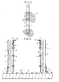
- each channel-like pillar 1 has a web 2 having a plurality of longitudinally elongate slots spaced apart in the longitudinal directions. Its opposite side flanges 3 each have a plurality of holes 4 spaced apart a suitable distance in the longitudinal directions.
- Clamp members 5 are secured to the pillar 1 at the upper and lower ends thereof. More specifically, a clamp member 5 is secured by a bolt and a nut to the outer surface of one side flange 3 at one end, and another clamp member 5 is secured in the same way to the outer surface of the other side flange 3 at the other end.
- the clamp member 5 is formed from a flat plate and has a stepped portion formed at its longitudinal center. It is secured by clamping the nut on the bolt which is inserted through a hole formed in it and a hole 4 formed in the side flange 3. At each end of the pillar, the clamp member 5 defines a small gap with the corresponding outer surface of the side flange 3.
- Pillars 1 as described above are erected in upright pairs in two rows such that their side flanges 3 oppose each other.
- the opposing side flanges 3 are those, to which the clamp members 5 are secured at the upper end.
- the pillars 1 of a pair are spaced apart by a spacer member e.g., a steel rod.
- the pillars 1 in a row are connected by a batten 6 extending at right angles to the line forming the pair of pillars.
- the batten 6 has an L-shaped section.
- One of its arms has a plurality of longitudinally elongate slots 7 spaced apart in the longitudinal direction. Its slotted portion is clamped between the clamp member 5 and associated side flange 3 of each pillar 1.
- the other arm projects toward the other row of the pillars 1.
- the pillars 1 in each row are also connected at their lower end by similar L-shaped batten with the arm without slots 7 clamped between the clamp member 5 and corresponding side flange 3 of each pillar 1 and the slotted arm projecting in the direction away from the other row of pillars 1.
- Parallel metal nets 8 are stretched over the facing sides of the pair rows of pillars 1.
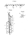
- Fig. 6 shows a metal net mounting snap 9. It is made of vinyl chloride but it may also be made of other synthetic resins or rubber. It has a disc- like head 10 and a plurality of locking portions 11 perpendicularly projecting from one side of the head 10.
- the locking portions 11 are four in number and define a cross-shaped space in section. Each has an outward projection at its mid-portion.
- the projection 12 is smoothly raised from the rest-of the locking portion 11 and smoothly terminates therein at the other end.
- the metal net is attached to the pillars 1 by the snaps 9 in the following way.
- Meshes of the metal net 8 are fitted in the locking portions 11 of the metal net mounting snaps 9, and then the snaps 9 are inserted into the holes 4 of the pillars 1.
- the locking portions 11 have the projections 12, and as they are inserted the outer diameter of the assembly of the projections 12 is reduced by an amount corresponding to the cross-shaped space so that the projections 12 can be pressure inserted through the hole 4.
- the projections 12 clear the hole, they are restored to the initial state by the elasticity of the locking portions 11.
- the metal net mounting snap 9 can not be readily removed. In this way, the metal net 8 can be held attached to the pillars 1 by the head 10 of each snap 9.
- the battens 6 are connected together to connect adjacent C-channel-shaped pillars by lapping a connecting member over opposed end portions of the battens and securing the connecting member by inserting bolts through the slots 7.
- the batters 6 connecting the lower ends of the pillars 1 are secured to a concrete subslab by passing concrete nails or the like through the slots 7 and driving them into the concrete.
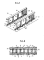
- FIGs. 7 to 11 show a different embodiment )of the present invention.
- a pair of frameworks 13 is erected on a concrete foundation 1 formed by placing concrete on site.
- the pair frameworks 13 are spaced apart a necessary distance.
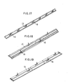
- the framework 13 consists of a lower liner 14, pillars 15 and an upper liner 16.
- the lower liner 14 is laid on the concrete foundation 37, and is secured to the same by a plurality of securing members 17.
- the pillars 15 are erected on the lower liner 14 at predetermined intervals in the longitudinal direction of the lower liner 14. They are coupled to the lower liner 14 by coupling members 18 as shown in detail in Figs. 10 and 11.
- the upper liner 16 is secured to the upper end of the pillars 15 by coupling members 18.
- the lower liner 14, pillars 15 and upper liner 16 have a channel section. They have a plurality of cut-and-raised pawls 19 formed on one or both side portions. They are assembled into the framework 13 such that the pawls 19 are directed to the opposite, framework 13 of the pair.
- the securing member 17 has an angle, and it is secured by means of nails, screws, etc. to the concrete foundation and lower liner 14.
- the coupling member 18 has an L-shaped form consisting of a horizontal section 20 and a vertical section 21.
- the horizontal section 20 has a pin 29 inserted through its substantial central portion from the above.
- a clamp member 22 is rotatably mounted on the pin 29.
- the coupling member 18 is secured to the upper or lower liner 14 or 16 such that the opposite side portions 23 of the liner are clamped between its horizontal section 20 and clamp member 22.
- the vertical section 21 has a plurality of vertically spaced-apart bifurcated clamp pieces 24 horizontally projecting from each of the opposite edges.
- the coupling member 18 is secured to the pillar 15 with the opposite side portions 23 of the pillar 15 clamped in the bifurcated clamp pieces 24.
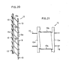
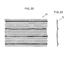
- metal nets 25 of metal lath, wire lath and ribbed lath or the like which are stretched over the inner side of the frameworks 13 by hooking them on the pawls 19, as shown in Figs. 22 and 23. If necessary, a spacer or spacers are mounted between the pair frameworks 13.
- reinforcing bars 26 are provided on the inner side of the metal nets 25, and then concrete is placed.
- the frameworks 13 are removed. If necessary, a finishing material such as mortar is coated on the surface of the metal nets 25.
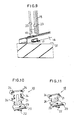
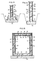
- Fig. 12 shows a retaining wall fabricated by the method of constructing concrete structure according to the present invention.
- first rubble- 40 is laid at the bottom of a trench, and a concrete subslab 41 is formed on the rubble 40.
- a pair of frameworks 13 is then erected on the concrete subslab 41 at a predetermined spacing.
- One of the frameworks 13 is inclined toward the inner side a certain angle.
- the frameworks 13 are supported from the outer side using supporting material such as battens 26, oblique supports 27, and angle pieces, for example.
- the framework 13 consists of an upper liner 16, pillars 15 and a lower liner 14. These components are metal members having a channel section and have a plurality of cut-and-raised pawls 19 formed on ' one or both side portions.
- the lower liners 14 are laid parallel to and at a predetermined spacing from each other on the concrete subslab 41 and secured on the concrete subslab 41 using securing members 17.
- the pillars 15 are erected on each of the lower liners 14 at predetermined intervals in the longitudinal direction thereof. They are secured to the lower liners 14 using coupling members 18 as shown in Figs. 10 and 11.
- the upper liners 16 are see red to the pillars 15 in respective rows using coupling members 18.
- metal nets 25 of metal or wire lath for example are stretched over the inner side of the frameworks 13 by hooking them to the cut-and-raised pawls 19. If necessary, the frameworks 13 are tied together using coupling bolts 28.
- reinforcing bars 26 are provided on the inner side of the metal nets 25, and then concrete 39 is poured.
- the frameworks 13 and support members supporting the same such as b attens 26, oblique supports 27, and angles etc. are removed.
- a finishing material such as mortar is subsequently coated on the surface of the metal nets 25.
- paper materials such as those used for roofing or the like may be preliminarily applied to the surface of the metal nets 25, and they may be separated after the poured concrete 39 has solidified. In this case, solidified concrete 39 will have a smooth and-flat surface so that the coating of the finishing material may be dispensed with.
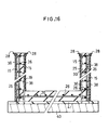
- Figs. 13 to 16 show respective different structures, i.e., a continuous footing, a garage, a storehouse, a pool and water tank.
- trench A is first formed, and rubble 40 is laid at the bottom of the trench A.
- a concrete subslab 41 is formed on the rubble 40.
- a plurality of pillars 15 are erected on the concrete subslab 41 at predetermined interval in the longitudinal direction of the trench A.
- the pillar 15 has a ladder-like intergral structure consisting of opposite side pillars 15a and coupling portions 15b connecting the pillars 15a.
- the pillars 15a ave a plurality of outwardly projecting pawls 19 spaced apart at predetermined interval in the vertical direction of pillars 15a.
- the pillars 15 are erected on the concrete subslab 41 by nailing them or inserting them into the concrete subslab 41.
- the upper ends of the pillars 15 are connected together by L-shaped liners 28
- metal nets 25 are stretched over both sid-es of the row of pillars 15 and are attached thereto by hooking them on the pawls 19 projecting from the pillars 15a and by bending the pawls 19.
- concrete 39 is poured into the space defined between the opposite side metal nets 25, and then a finishing material 38, such as mortar is coated on the surfaces of the:metal nets 25.
- reinforcing bars may be provided in the space between the metal nets 25 before pouring the concrete 39.
- a spacer holder 34 as shown in Fig. 24 may be used.
- the spacer holder 34 is secured to the opposite side liners 28 by inserting projections 30 and 31 through holes 32 formed in the liners 28.
- the distance between the projection pairs 30 and 31 may be adjusted by loosening set screws 33, moving a slide member 35 in the longitudinal direction of the spacer holder which may be a steel pipe and clamping the set screws 33 again with the slide member 35 at a predetermined position.
- the time necessary for manufacturing and assembling as in the prior art framework can be reduced, and particularly the disassembling operation can be carried out quickly. It is thus possible to simplify the construction and greatly reduce the time taken.
Applications Claiming Priority (6)
| Application Number | Priority Date | Filing Date | Title |
|---|---|---|---|
| JP159621/82 | 1982-10-21 | ||
| JP159620/82 | 1982-10-21 | ||
| JP15962182U JPS5963154U (ja) | 1982-10-21 | 1982-10-21 | 金網製型枠 |
| JP159622/82 | 1982-10-21 | ||
| JP15962282U JPS5963155U (ja) | 1982-10-21 | 1982-10-21 | 金網取付け用スナツプ |
| JP1982159620U JPS5963153U (ja) | 1982-10-21 | 1982-10-21 | 金網製型枠用支柱 |
Publications (2)
| Publication Number | Publication Date |
|---|---|
| EP0107460A2 true EP0107460A2 (en) | 1984-05-02 |
| EP0107460A3 EP0107460A3 (en) | 1985-07-10 |
Family
ID=27321570
Family Applications (1)
| Application Number | Title | Priority Date | Filing Date |
|---|---|---|---|
| EP83306251A Withdrawn EP0107460A3 (en) | 1982-10-21 | 1983-10-14 | Method of constructing concrete structure |
Country Status (2)
| Country | Link |
|---|---|
| EP (1) | EP0107460A3 (un) |
| CA (1) | CA1224934A (un) |
Cited By (8)
| Publication number | Priority date | Publication date | Assignee | Title |
|---|---|---|---|---|
| WO1995012719A1 (fr) * | 1993-11-02 | 1995-05-11 | Coffratherm | Fabrication de coffrage |
| WO1996035024A1 (en) * | 1995-05-04 | 1996-11-07 | Ma-Rakennus J. Mäntylä Ky | Wall construction and method of manufacturing a wall construction |
| FR2769033A1 (fr) * | 1997-10-01 | 1999-04-02 | Jean Claude Maitre | Procede de realisation d'ouvrages en beton et lattis metalliques pour sa mise en oeuvre |
| FR2782740A1 (fr) * | 1998-08-28 | 2000-03-03 | Ghasnavi Eric Moavensadeh | Coffrage losanges a armature integree |
| WO2005017272A1 (en) * | 2003-08-07 | 2005-02-24 | Storsack Uk Ltd | A method and system for producing a concrete structure |
| GB2452792B (en) * | 2007-04-05 | 2012-09-05 | Kenneth Macleod | Method of constructing a building structure by cladding a framework |
| GB2529688A (en) * | 2014-08-29 | 2016-03-02 | Simon Widdowfield | An apparatus for forming a structure |
| ITUA20164209A1 (it) * | 2016-06-08 | 2017-12-08 | Andrea Vese | Parete e metodo per la sua realizzazione |
Citations (5)
| Publication number | Priority date | Publication date | Assignee | Title |
|---|---|---|---|---|
| GB247790A (en) * | 1925-04-29 | 1926-02-25 | William Cornell Buckhout | Improvements in wall construction |
| GB252279A (en) * | 1925-02-26 | 1926-05-26 | Edward Connell Caley | Improvements in houses and like buildings, yard and like walls and in the method of constructing the same |
| FR965935A (fr) * | 1948-04-30 | 1950-09-26 | Immobiliere Soc | Dispositif de coffrage |
| US3638382A (en) * | 1969-12-22 | 1972-02-01 | Ronald E Merrill | Form for a concrete wall structure |
| EP0055504A1 (en) * | 1980-12-31 | 1982-07-07 | Nagron Steel and Aluminium B.V. | Method and structural element for erecting a building and building thus formed |
-
1983
- 1983-10-14 EP EP83306251A patent/EP0107460A3/en not_active Withdrawn
- 1983-10-20 CA CA000439394A patent/CA1224934A/en not_active Expired
Patent Citations (5)
| Publication number | Priority date | Publication date | Assignee | Title |
|---|---|---|---|---|
| GB252279A (en) * | 1925-02-26 | 1926-05-26 | Edward Connell Caley | Improvements in houses and like buildings, yard and like walls and in the method of constructing the same |
| GB247790A (en) * | 1925-04-29 | 1926-02-25 | William Cornell Buckhout | Improvements in wall construction |
| FR965935A (fr) * | 1948-04-30 | 1950-09-26 | Immobiliere Soc | Dispositif de coffrage |
| US3638382A (en) * | 1969-12-22 | 1972-02-01 | Ronald E Merrill | Form for a concrete wall structure |
| EP0055504A1 (en) * | 1980-12-31 | 1982-07-07 | Nagron Steel and Aluminium B.V. | Method and structural element for erecting a building and building thus formed |
Cited By (12)
| Publication number | Priority date | Publication date | Assignee | Title |
|---|---|---|---|---|
| WO1995012719A1 (fr) * | 1993-11-02 | 1995-05-11 | Coffratherm | Fabrication de coffrage |
| FR2712016A1 (fr) * | 1993-11-02 | 1995-05-12 | Coffratherm Ste Civile Invente | Procédé de fabrication de parois de coffrage pour bâtiment et chaîne de fabrication s'y rapportant. |
| WO1996035024A1 (en) * | 1995-05-04 | 1996-11-07 | Ma-Rakennus J. Mäntylä Ky | Wall construction and method of manufacturing a wall construction |
| US5906081A (en) * | 1995-05-04 | 1999-05-25 | Ma-Rakennus J. Mantyla Ky | Wall construction and method of manufacturing a wall construction |
| AP891A (en) * | 1995-05-04 | 2000-11-15 | Mantyla Ky Ma Rakennus J | Wall construction and method of manufacturing a wall construction. |
| FR2769033A1 (fr) * | 1997-10-01 | 1999-04-02 | Jean Claude Maitre | Procede de realisation d'ouvrages en beton et lattis metalliques pour sa mise en oeuvre |
| FR2782740A1 (fr) * | 1998-08-28 | 2000-03-03 | Ghasnavi Eric Moavensadeh | Coffrage losanges a armature integree |
| WO2005017272A1 (en) * | 2003-08-07 | 2005-02-24 | Storsack Uk Ltd | A method and system for producing a concrete structure |
| GB2452792B (en) * | 2007-04-05 | 2012-09-05 | Kenneth Macleod | Method of constructing a building structure by cladding a framework |
| GB2529688A (en) * | 2014-08-29 | 2016-03-02 | Simon Widdowfield | An apparatus for forming a structure |
| ITUA20164209A1 (it) * | 2016-06-08 | 2017-12-08 | Andrea Vese | Parete e metodo per la sua realizzazione |
| WO2017211454A1 (en) | 2016-06-08 | 2017-12-14 | Vese Andrea | Wall and method for manufacturing it |
Also Published As
| Publication number | Publication date |
|---|---|
| CA1224934A (en) | 1987-08-04 |
| EP0107460A3 (en) | 1985-07-10 |
Similar Documents
| Publication | Publication Date | Title |
|---|---|---|
| US8359797B2 (en) | Structure constructed using precast members and method of constructing the same | |
| US4211043A (en) | Precast concrete building module form | |
| CA1100325A (en) | Prefabricated wall designed in particular for the construction of dwelling houses | |
| KR102243984B1 (ko) | 자립형 거푸집을 이용한 합벽 순타 시공용 무지주 거푸집 시스템 및 이의 시공 방법 | |
| CA1179519A (en) | Precast building element and method | |
| EP0107460A2 (en) | Method of constructing concrete structure | |
| EP0183698B1 (en) | Building panels | |
| EP0107749A1 (en) | Aseismatic building structure | |
| JP2001342639A (ja) | 埋設型枠 | |
| GB2056538A (en) | Shuttering system | |
| JP2736224B2 (ja) | 型枠及びモルタル、コンクリート等の施行方法 | |
| JP3262600B2 (ja) | コンクリート主塔及び横梁の構築方法 | |
| RU2248433C1 (ru) | Несъемная опалубка, способ ее сборки и способ возведения монолитных стен и сооружений в несъемной опалубке | |
| JPH0455091Y2 (un) | ||
| JP3284383B2 (ja) | Src梁構築用の支持金物 | |
| JPH0332678Y2 (un) | ||
| JPH0455090Y2 (un) | ||
| JP2700637B2 (ja) | 斜面安定構造物 | |
| JPH02209523A (ja) | 法枠用型枠 | |
| JPH0449253Y2 (un) | ||
| TW202223209A (zh) | 以型鋼取代部分鋼筋來組立鋼筋混凝土構造之加勁結構 | |
| JPH0133717Y2 (un) | ||
| JPH0455092Y2 (un) | ||
| JPS58173238A (ja) | 鉄筋コンクリ−ト建築物に於ける壁体の施工法 | |
| JPH0417718Y2 (un) |
Legal Events
| Date | Code | Title | Description |
|---|---|---|---|
| PUAI | Public reference made under article 153(3) epc to a published international application that has entered the european phase |
Free format text: ORIGINAL CODE: 0009012 |
|
| AK | Designated contracting states |
Designated state(s): BE DE FR GB IT NL |
|
| 17P | Request for examination filed |
Effective date: 19840702 |
|
| PUAL | Search report despatched |
Free format text: ORIGINAL CODE: 0009013 |
|
| AK | Designated contracting states |
Designated state(s): BE DE FR GB IT NL |
|
| 17Q | First examination report despatched |
Effective date: 19860407 |
|
| STAA | Information on the status of an ep patent application or granted ep patent |
Free format text: STATUS: THE APPLICATION IS DEEMED TO BE WITHDRAWN |
|
| 18D | Application deemed to be withdrawn |
Effective date: 19860819 |