EP0030469A2 - Video tape recorder including tracking apparatus - Google Patents
Video tape recorder including tracking apparatus Download PDFInfo
- Publication number
- EP0030469A2 EP0030469A2 EP80304413A EP80304413A EP0030469A2 EP 0030469 A2 EP0030469 A2 EP 0030469A2 EP 80304413 A EP80304413 A EP 80304413A EP 80304413 A EP80304413 A EP 80304413A EP 0030469 A2 EP0030469 A2 EP 0030469A2
- Authority
- EP
- European Patent Office
- Prior art keywords
- video
- signal
- signals
- voltage
- circuit
- Prior art date
- Legal status (The legal status is an assumption and is not a legal conclusion. Google has not performed a legal analysis and makes no representation as to the accuracy of the status listed.)
- Granted
Links
Images


Classifications
-
- G—PHYSICS
- G11—INFORMATION STORAGE
- G11B—INFORMATION STORAGE BASED ON RELATIVE MOVEMENT BETWEEN RECORD CARRIER AND TRANSDUCER
- G11B5/00—Recording by magnetisation or demagnetisation of a record carrier; Reproducing by magnetic means; Record carriers therefor
- G11B5/48—Disposition or mounting of heads or head supports relative to record carriers ; arrangements of heads, e.g. for scanning the record carrier to increase the relative speed
- G11B5/58—Disposition or mounting of heads or head supports relative to record carriers ; arrangements of heads, e.g. for scanning the record carrier to increase the relative speed with provision for moving the head for the purpose of maintaining alignment of the head relative to the record carrier during transducing operation, e.g. to compensate for surface irregularities of the latter or for track following
- G11B5/584—Disposition or mounting of heads or head supports relative to record carriers ; arrangements of heads, e.g. for scanning the record carrier to increase the relative speed with provision for moving the head for the purpose of maintaining alignment of the head relative to the record carrier during transducing operation, e.g. to compensate for surface irregularities of the latter or for track following for track following on tapes
- G11B5/588—Disposition or mounting of heads or head supports relative to record carriers ; arrangements of heads, e.g. for scanning the record carrier to increase the relative speed with provision for moving the head for the purpose of maintaining alignment of the head relative to the record carrier during transducing operation, e.g. to compensate for surface irregularities of the latter or for track following for track following on tapes by controlling the position of the rotating heads
Definitions
- This invention relates to a video tape recorder for recording and reproducing video signals on a magnetic tape, and more particularly to position control of a video head when a plurality of video heads are used to reproduce the video signal recorded in a magnetic tape during reproduction.
- a plurality of video heads are mounted on an electro-mechanical transducer, to which a dither signal is applied.
- the positions of video heads with respect to the video tracks are detected from the dither signal and the envelopes of the signals reproduced by the video heads, thereby constituting a negative feedback loop to control tracking.
- the present invention provides a video signal reproducing apparatus for reproducing video signals from a magnetic tape on which video signals are recorded as video tracks inclined at an angle with respect to the lengthwise direction of said magnetic tape, said apparatus comprising a tracking device having video heads for scanning said video tracks to obtain reproducing signals, electric-mechanical transducer means for moving said video heads in a direction perpendicular to the scanning direction of said video-tracks, a demodulator for demodulating said reproduction signal to obtain reproduced video signals, a vertical synchronizing detector circuit for separating vertical synchronizing signals from said reproduced video signals, a pulse processing circuit for detecting rotary phases of said video heads, a time-voltage conversion circuit for converting into voltage cycles of said vertical synchronizing signals by means of said rotary phases of said video heads derived from said pulse processing circuit, a holding circuit for holding output voltage of said time-voltage conversion circuit, a level comparison circuit for comparing output voltages of said time-voltage conversion circuit and of the holding circuit, a control voltage generating circuit for comparing the output of said level
- the tracking apparatus of the invention is such as to allow high quality reproduction during normal, slow-motion, or fast-motion modes of reproduction.
- Figure 1 shows a block diagram of a principal portion of an embodiment of a video tape recording and reproducing apparatus including an auto-tracking apparatus, in which reference numerals 1 and 2 designate video heads having equal azimuth angles, e.g. 6 0 , and which are mounted on a free end of respective electric-mechanical transducers 18 and 19, such as bimorph type piezo-electric elements.
- the electric-mechanical transducers 18 and 19 are mounted at their other ends on a rotatable disc 4.
- a magnet 3 is mounted on the disc 4 and a stationary rotary phase detector 5 is provided adjacent the path of movement of the magnet 3 for detecting the rotary phases of the video heads 1 and 2.
- the disc 4 is driven by a d.c.
- a magnetic tape (not shown) is wrapped around the circumference of the rotary disc 4 for about 180 o and is driven at constant speed by a capstan and pinch rollers.
- Such magnetic tape drive system is well-known and not shown in the drawing or described in detail.
- Output signals from the video heads 1 and 2 are fed via a rotary transformer 7 to a pre-amplifier 8.
- RF signals from video heads 1 and 2 are alternately switched at the pre-amplifier 8 by a signal (to be hereinafter called the head switch signal) comprising the output signal of the rotary phase detector 5 after processing by a pulse processing unit 9.
- the output from pre-amplifier 8 is fed to an envelope detector 10 and demodulator 11.
- the envelope detector 10 forms part of a tracking control signal generator 17 which also includes a synchronizing detector 13 and a dither signal generator 14.
- the detector 10 detects amplitude distortion of RF signals reproduced by video heads 1 and 2 and provides an output signal which is fed to one input terminal of the synchronizing detector 13.
- An output signal of a dither signal generator 14 is fed to an input terminal of synchronizing detector 13 whose output signal is fed to an adder 15 where it is added to a further output signal of the dither signal generator 14 and the thus produced signal is fed to DC amplifiers 16 and 17.
- the amplifiers ensure that the thus produced signal is amplified sufficiently to drive the transducers 18 and 19 and the output from the adder 15 is applied to the transducers via conductive brushes 20 and slip rings 21, the slip rings 21 being mounted on the shaft 6.
- One output signal of demodulator 11 is fed to an output terminal 12 and the other output signal is fed to a time-voltage conversion unit 23 through a vertical synchronizing signal detecting unit 22.
- the output of the time-voltage conversion unit 23 is fed to a holding circuit 24 and directly to a level comparison circuit 25.
- the output of the holding circuit 24 is fed to the adder 15 via the level comparison circuit 25 and a control voltage generator 26.
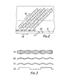
- Figure 2 is a view exemplary of track patterns recorded on a magnetic tape 28, in which references Ao, Bo, A 1 , B 1 and A 2 designate video tracks where one field of each video signal is recorded as a block i.e. it is not segmented.
- a , A 1 and A 2 are recorded by video heads (not shown) of an equal azimuth angle (+6° in this embodiment of the invention), and B 0 and B 1 by video heads (not shown) of another azimuth angle (-6 0 in this embodiment).
- oblique lines at each track represent recording positions of horizontal synchronizing signals and dotted portions represent recorded positions of vertical synchronizing signals.
- Tc designates a control track on which a control signal showing the recorded position of the video signal is recorded.
- a control signal 31 or 32 is recorded on the control track for each frame, so that the starting point of track A 0 and control signal 31, are recorded at the same timing and that of track A 1 and control signal 32 are recorded similarly.
- Pulse processing unit 9 employs, for example, a mono-multi-vibrator circuit in three steps to obtain a head switching signal as shown in Figure 3 (D), in which it is assumed that the leading edge of the signal is coincident with the timing when video head 2 starts scanning a track, and that the trailing edge is coincident with the timing when video head 2 starts scanning a track.
- reproduced signals from video heads 1 and 2 are alternately applied to the pre-amplifier 8 by means of the head switch signal from the pulse processing unit 9, and converted into a continuous signal to be fed to the tracking control signal generator 27 and the demodulator 11.
- the envelope detector 10 of the tracking control signal generator 27 is supplied with the reproducing signal as shown in Figure 3 (A).
- Envelope detector 10 comprises a conventional diode detection circuit which generates an output signal as shown in Figure 3 (B).
- Synchronizing detector 13 is supplied with the envelope signal and the output signal from terminal X of dither signal generator 14 as shown in Figure 3 (C).
- Such a tracking control signal is added by adder 15 with the output signal (in phase with the output at terminal X) from terminal Y of the dither signal generator 14, and applied to transducers 18 and 19 through d.c. amplifiers 16 and 17, conductive brushes 20 and slip rings 21. Consequently, the scan positions of video heads 1 and 2 are compensated to he on track, thereby completing the control loop.
- RF signals shown in Figure 3 (A) represent upward shifts of video heads 1 and 2 with respect to track A 1 .
- the demodulator 11 feeds the reproduced video signal shown in Figure 4 (a) to the vertical synchronizing signal detector unit 22 where the vertical synchronizing signal as shown in Figure 4 (b) is separated from the video signal and is fed to one input terminal of the time-voltage conversion circuit 23, whose other input terminal is supplied with the head switch signal as shown in Figure 4 (c), from pulse processing unit 9.
- FIG. 5 An example of the time-voltage conversion circuit 23 is shown in Figure 5 where an input terminal Vs is supplied with the vertical synchronizing signal shown in Figure 4 (b) and an input terminal H S is supplied with the head switch signal shown in Figure 4 (c).
- the input terminal V S is connected to one input terminal at a two input NAND gate circuit 34 and to one input terminal of a two input NAND gate 35.
- the input terminal H S is similarly fed into the other input terminal of NAND gate circuit 34 and into the other input terminal at NAND gate circuit 35 via an inverter 33.
- vertical synchronizing signals as shown in Figures 4 (d) and (e) are obtained at the outputs of NAND gate circuits 34 and 35 respectively.
- the output of the NAND gate 34 is fed to the set input terminal S of an RS flip-flop composed of NAND gates 36, 37 and to the reset input terminal R of a further RS flip-flop composed of NAND gates 38 and 39.
- the output of the NAND gate 35 is connected to the reset terminal R of the RS flip-flop composed of NAND gates 36, 37 and to the set terminal S of the other RS flip-flop.
- signals shown in Figures 4 (f) and (g) represent, for example, a time period of H level corresponding to one field time of video signal.
- the crest value of voltage wave form in Figure 4 (g) is held for the next one field period by holding circuit 24 and compared with the crest value at the next field, i.e., voltage wave form in Figure 4 (i), by use of the level comparison circuit 25.
- Control voltage generating circuit 26 when the output signal of level comparison circuit 25 is equal to reference voltage corresponding to the aforesaid -3H, adds zero voltage to adder 15 assuming that no track jumping occurs.
- the video heads 1 and 2 can be kept in an on-track condition by means of the control loop while compensating the track jumping.
- the magnetic tape speed during reproduction is equal to that during recording, but the track jumping, of course, can be discriminated at different speeds using the same construction.
- the video heads of single azimuth angle (+6° in the embodiment) reproduce the video tracks comprising video tracks recorded by the video head of an azimuth angle of +60 and those recorded by the video head of an azimuth angle of -6°, which are arranged alternately with each other.
- a combination of video head of an azimuth angle of +6 0 with video head of that of -6° may detect the track jumping through the same construction for reproduction.
Abstract
Description
- This invention relates to a video tape recorder for recording and reproducing video signals on a magnetic tape, and more particularly to position control of a video head when a plurality of video heads are used to reproduce the video signal recorded in a magnetic tape during reproduction.
- Conventionally, in reproduction, a plurality of video heads are mounted on an electro-mechanical transducer, to which a dither signal is applied. The positions of video heads with respect to the video tracks are detected from the dither signal and the envelopes of the signals reproduced by the video heads, thereby constituting a negative feedback loop to control tracking.
- Such an arrangement, when using a plurality of video heads for reproduction, has each video head constituting a negative feedback loop on the basis of its reproduction envelope. As a result, the problem has been created in that it is impossible to discriminate whether each video head is scanning a desired track or an adjacent track and this is the cause of so-called track jumping.
- The present invention provides a video signal reproducing apparatus for reproducing video signals from a magnetic tape on which video signals are recorded as video tracks inclined at an angle with respect to the lengthwise direction of said magnetic tape, said apparatus comprising a tracking device having video heads for scanning said video tracks to obtain reproducing signals, electric-mechanical transducer means for moving said video heads in a direction perpendicular to the scanning direction of said video-tracks, a demodulator for demodulating said reproduction signal to obtain reproduced video signals, a vertical synchronizing detector circuit for separating vertical synchronizing signals from said reproduced video signals, a pulse processing circuit for detecting rotary phases of said video heads, a time-voltage conversion circuit for converting into voltage cycles of said vertical synchronizing signals by means of said rotary phases of said video heads derived from said pulse processing circuit, a holding circuit for holding output voltage of said time-voltage conversion circuit, a level comparison circuit for comparing output voltages of said time-voltage conversion circuit and of the holding circuit, a control voltage generating circuit for comparing the output of said level comparison circuit with a reference voltage and generating voltage when said reference voltage and output voltage are not coincident with each other, a tracking control signal generating circuit for controlling said video head positions, and an adder for adding an output signal from said control voltage generating circuit with an output signal from said tracking control signal generating circuit, and generating a signal for application to said electric-mechanical transducer, thereby allowing said video heads to scan video tracks.
- The tracking apparatus of the invention is such as to allow high quality reproduction during normal, slow-motion, or fast-motion modes of reproduction.
- Features and advantages of the present invention will become more apparent from the following description of a preferred embodiment when taken in conjunction with the accompanying drawings, in which:-
- Figure 1 is a view of the principal portion of a video tape recorder;
- Figure 2 is a view of an example of track patterns recorded on a magnetic tape;
- Figures 3 (A), (B), (C), and (D) show waveforms to assist in understanding the operation of the apparatus shown in Figure 1;
- Figures 4 (a), (b), (c), (d), (e), (f), (g), (h), and (i) each show a further waveform for assisting understanding of the operation of the apparatus shown in Figure 1;
- Figure 5 is a block diagram of a time-voltage conversion unit used in an embodiment of the invention;
- Figures 6 (a), (b), (c), and (d) show further waveforms for explaining the operation of the apparatus shown in Figure 1; and
- Figures 7.(a), (b), (c), (d), (e), and (f) are waveforms of another example of operation of the apparatus shown in Figure 1.
- Figure 1 shows a block diagram of a principal portion of an embodiment of a video tape recording and reproducing apparatus including an auto-tracking apparatus, in which reference numerals 1 and 2 designate video heads having equal azimuth angles, e.g. 60, and which are mounted on a free end of respective electric-
mechanical transducers mechanical transducers rotatable disc 4. A magnet 3 is mounted on thedisc 4 and a stationary rotary phase detector 5 is provided adjacent the path of movement of the magnet 3 for detecting the rotary phases of the video heads 1 and 2. Thedisc 4 is driven by a d.c. motor (not shown) through a shaft 6 and rotates at a speed of about 30 Hz. Phase control of thedisc 4 is well-known and is therefore omitted from this description. A magnetic tape (not shown) is wrapped around the circumference of therotary disc 4 for about 180o and is driven at constant speed by a capstan and pinch rollers. Such magnetic tape drive system is well-known and not shown in the drawing or described in detail. - Output signals from the video heads 1 and 2 are fed via a rotary transformer 7 to a pre-amplifier 8. RF signals from video heads 1 and 2 are alternately switched at the pre-amplifier 8 by a signal (to be hereinafter called the head switch signal) comprising the output signal of the rotary phase detector 5 after processing by a
pulse processing unit 9. The output from pre-amplifier 8 is fed to anenvelope detector 10 anddemodulator 11. - The
envelope detector 10 forms part of a trackingcontrol signal generator 17 which also includes asynchronizing detector 13 and adither signal generator 14. Thedetector 10 detects amplitude distortion of RF signals reproduced by video heads 1 and 2 and provides an output signal which is fed to one input terminal of the synchronizingdetector 13. An output signal of adither signal generator 14 is fed to an input terminal of synchronizingdetector 13 whose output signal is fed to anadder 15 where it is added to a further output signal of thedither signal generator 14 and the thus produced signal is fed toDC amplifiers transducers adder 15 is applied to the transducers viaconductive brushes 20 andslip rings 21, theslip rings 21 being mounted on the shaft 6. - One output signal of
demodulator 11 is fed to anoutput terminal 12 and the other output signal is fed to a time-voltage conversion unit 23 through a vertical synchronizingsignal detecting unit 22. The output of the time-voltage conversion unit 23 is fed to aholding circuit 24 and directly to alevel comparison circuit 25. The output of theholding circuit 24 is fed to theadder 15 via thelevel comparison circuit 25 and acontrol voltage generator 26. - Next, a conventional example and an embodiment of the invention will be detailed of their operations.
- Figure 2 is a view exemplary of track patterns recorded on a
magnetic tape 28, in which references Ao, Bo, A1, B1 and A2 designate video tracks where one field of each video signal is recorded as a block i.e. it is not segmented. A , A1 and A2 are recorded by video heads (not shown) of an equal azimuth angle (+6° in this embodiment of the invention), and B0 and B1 by video heads (not shown) of another azimuth angle (-60 in this embodiment). - In addition, oblique lines at each track represent recording positions of horizontal synchronizing signals and dotted portions represent recorded positions of vertical synchronizing signals.
- Tc designates a control track on which a control signal showing the recorded position of the video signal is recorded. A
control signal control signal 31, are recorded at the same timing and that of track A1 andcontrol signal 32 are recorded similarly. - Rotary phases of video heads 1 and 2 are detected using the magnet 3 and the rotary phase detector 5.
Pulse processing unit 9 employs, for example, a mono-multi-vibrator circuit in three steps to obtain a head switching signal as shown in Figure 3 (D), in which it is assumed that the leading edge of the signal is coincident with the timing when video head 2 starts scanning a track, and that the trailing edge is coincident with the timing when video head 2 starts scanning a track. Hence, reproduced signals from video heads 1 and 2 are alternately applied to the pre-amplifier 8 by means of the head switch signal from thepulse processing unit 9, and converted into a continuous signal to be fed to the trackingcontrol signal generator 27 and thedemodulator 11. Theenvelope detector 10 of the trackingcontrol signal generator 27 is supplied with the reproducing signal as shown in Figure 3 (A).Envelope detector 10 comprises a conventional diode detection circuit which generates an output signal as shown in Figure 3 (B). Synchronizingdetector 13 is supplied with the envelope signal and the output signal from terminal X ofdither signal generator 14 as shown in Figure 3 (C). As a result, when video head 1 is scanning video track A1 as desired, if video head 1 shifts upwardly, the synchronizingdetector 13 produces a negative voltage as the tracking control signal, and conversely, a positive voltage if video head 1 shifts downwardly; the output becomes zero when on track. Such a tracking control signal is added byadder 15 with the output signal (in phase with the output at terminal X) from terminal Y of thedither signal generator 14, and applied totransducers amplifiers conductive brushes 20 andslip rings 21. Consequently, the scan positions of video heads 1 and 2 are compensated to he on track, thereby completing the control loop. In addition, RF signals shown in Figure 3 (A) represent upward shifts of video heads 1 and 2 with respect to track A1. - However, RF signals the same as signals shown in Figure 3 (A) are given to complete the control loop when video head 1 scans track A and video head 2 scans track A2' so that both shift upwardly.
- The
demodulator 11 feeds the reproduced video signal shown in Figure 4 (a) to the vertical synchronizingsignal detector unit 22 where the vertical synchronizing signal as shown in Figure 4 (b) is separated from the video signal and is fed to one input terminal of the time-voltage conversion circuit 23, whose other input terminal is supplied with the head switch signal as shown in Figure 4 (c), frompulse processing unit 9. - An example of the time-
voltage conversion circuit 23 is shown in Figure 5 where an input terminal Vs is supplied with the vertical synchronizing signal shown in Figure 4 (b) and an input terminal HS is supplied with the head switch signal shown in Figure 4 (c). The input terminal VS is connected to one input terminal at a two inputNAND gate circuit 34 and to one input terminal of a twoinput NAND gate 35. The input terminal HS is similarly fed into the other input terminal ofNAND gate circuit 34 and into the other input terminal atNAND gate circuit 35 via aninverter 33. Hence, vertical synchronizing signals as shown in Figures 4 (d) and (e) are obtained at the outputs ofNAND gate circuits NAND gate 34 is fed to the set input terminal S of an RS flip-flop composed ofNAND gates NAND gates NAND gate 35 is connected to the reset terminal R of the RS flip-flop composed ofNAND gates - Next, in an integrating circuit comprising resistances R1 and R2' condensers C1 and C2'
operational amplifiers magnetic tape 28 recorded at the azimuth angle. By use of video heads 1 and 2 of the same azimuth angles, and assuming thattape 28 is travelling at speed equal to that for recording, continuous RF signals as shown in Figure 3 (A) are obtained in such a manner that, for example, assuming that video head 1 scans video track A1 at the first field, video head 2 tends to scan the starting point of video track B1 at the second field. However, the aforesaid control loop allows video head 2 to move in a direction perpendicular with respect to the video track by one pitch of video track, whereby video head 2 scans video track A1, which is because the vertical synchronizing signal cycles differ due to different scanning time between the starting point of video track scanning and the vertical synchronizing signal. In this instance, the vertical synchronizing signal cycles, when video tracks are recorded in a range of 1.5H (1H = one cycle of horizontal synchronizing signal), become 261H and 264H. As a result, the voltage wave forms shown in Figures 4 (g) and (i) are similarly different from each other. - Next, the crest value of voltage wave form in Figure 4 (g) is held for the next one field period by holding
circuit 24 and compared with the crest value at the next field, i.e., voltage wave form in Figure 4 (i), by use of thelevel comparison circuit 25. Thelevel comparison circuit 25 subtracts the voltage wave forms in Figures 4 (g) and (i) so as to output voltage corresponding to 261H - 264H = -3H. Controlvoltage generating circuit 26, when the output signal oflevel comparison circuit 25 is equal to reference voltage corresponding to the aforesaid -3H, adds zero voltage to adder 15 assuming that no track jumping occurs. - However, when the video head scans track A2, in other words, when the track jumping occurs, video signal shown in Figure 6 (a) is reproduced. Furthermore, vertical synchronizing signals as shown in Figure 6 (b) are reproduced. Voltage wave forms as shown in Figures6 (c) and (d) are derived from the time-
voltage conversion circuit 23.Level comparison circuit 25, which is driven similarly to the case in Figure 4 by the vertical synchronizing signal. in Figure 6 (b) separated from the video signal shown in Figure 6 (a), outputs voltage corresponding to 264H-261H=3H. Controlvoltage generating circuit 26 is constructed to discriminate the occurrence of no track-jumping when level comparison voltage at the first and second fields is equal to reference voltage corresponding to -3H. Hence, sincelevel comparison circuit 25, in Figure 6, outputs voltage corresponding to +3H, controlvoltage generating circuit 26 feeds to adder 15 voltage necessary to move video head 2 downwardly at two pitches of video track. - Accordingly, by using the above arrangement, the video heads 1 and 2 can be kept in an on-track condition by means of the control loop while compensating the track jumping.
- In addition, in the embodiment of the invention, the magnetic tape speed during reproduction is equal to that during recording, but the track jumping, of course, can be discriminated at different speeds using the same construction.
- In the embodiment of the invention, the video heads of single azimuth angle (+6° in the embodiment) reproduce the video tracks comprising video tracks recorded by the video head of an azimuth angle of +60 and those recorded by the video head of an azimuth angle of -6°, which are arranged alternately with each other. Alternatively, a combination of video head of an azimuth angle of +60 with video head of that of -6° may detect the track jumping through the same construction for reproduction. Alternatively, for example, when voltage wave forms in Figures 7 (e) and (f) corresponding to the number of horizontal synchronizing signals shown in Figures 7 (c) and (d) and reproduced for a time period at H level of signal wave forms as shown in Figures 4 (f) and (h) is compared with
level comparison circuit 25, the same effect is obtainable in the embodiment of the invention because of the above comparison means measurement of the vertical synchronizing signal cycles. In addition, wave forms shown in Figures 7 (a) and (b) correspond to wave forms shown in Figures 6 (a) and (b).
Claims (3)
Applications Claiming Priority (2)
| Application Number | Priority Date | Filing Date | Title |
|---|---|---|---|
| JP15955179A JPS5683835A (en) | 1979-12-07 | 1979-12-07 | Tracking device |
| JP159551/79 | 1979-12-07 |
Publications (3)
| Publication Number | Publication Date |
|---|---|
| EP0030469A2 true EP0030469A2 (en) | 1981-06-17 |
| EP0030469A3 EP0030469A3 (en) | 1981-12-16 |
| EP0030469B1 EP0030469B1 (en) | 1984-05-09 |
Family
ID=15696209
Family Applications (1)
| Application Number | Title | Priority Date | Filing Date |
|---|---|---|---|
| EP80304413A Expired EP0030469B1 (en) | 1979-12-07 | 1980-12-05 | Video tape recorder including tracking apparatus |
Country Status (4)
| Country | Link |
|---|---|
| US (1) | US4389686A (en) |
| EP (1) | EP0030469B1 (en) |
| JP (1) | JPS5683835A (en) |
| DE (1) | DE3067787D1 (en) |
Cited By (2)
| Publication number | Priority date | Publication date | Assignee | Title |
|---|---|---|---|---|
| EP0043739A1 (en) * | 1980-07-09 | 1982-01-13 | Matsushita Electric Industrial Co., Ltd. | Tracking system |
| FR2566952A1 (en) * | 1984-06-28 | 1986-01-03 | Enertec | TRACK TRACKING ALIGNMENT FOR ROTATING MAGNETIC HEAD |
Families Citing this family (5)
| Publication number | Priority date | Publication date | Assignee | Title |
|---|---|---|---|---|
| JPS5880979A (en) * | 1981-11-09 | 1983-05-16 | Matsushita Electric Ind Co Ltd | Tracking device |
| JPS6352362U (en) * | 1986-09-24 | 1988-04-08 | ||
| US4933784A (en) * | 1988-10-31 | 1990-06-12 | Ampex Corporation | Automatic head position tracking system for video signals recorded in a segmented format |
| US5384676A (en) * | 1991-04-19 | 1995-01-24 | Mitsubishi Denki Kabushiki Kaisha | Magnetic head position controller in a magnetic recording and reproducing apparatus |
| WO2013065154A1 (en) | 2011-11-02 | 2013-05-10 | トヨタ自動車 株式会社 | Turbine housing and exhaust turbine supercharger |
Citations (10)
| Publication number | Priority date | Publication date | Assignee | Title |
|---|---|---|---|---|
| FR2293118A1 (en) * | 1974-11-26 | 1976-06-25 | Sony Corp | VIDEO SIGNAL PLAYBACK INSTALLATION |
| FR2360222A1 (en) * | 1976-07-30 | 1978-02-24 | Philips Nv | VIDEO SIGNAL REPRODUCING APPARATUS INCLUDING A TRACK ERROR CORRECTION SYSTEM |
| FR2386097A1 (en) * | 1977-03-28 | 1978-10-27 | Ibm | MAGNETIC HEAD DOESN'T GENERATE PARASITE SIGNALS WHEN READING / WRITING DATA TRACKS LOCATED BY SERVO TRACKS |
| US4141047A (en) * | 1977-09-12 | 1979-02-20 | Sony Corporation | Method and apparatus for correcting tracking errors of a transducer which scans parallel record tracks |
| FR2399093A1 (en) * | 1977-07-28 | 1979-02-23 | Grundig Emv | DEVICE FOR PRECISE EXPLOITATION OF TRACKS OF A MAGNETIC TAPE IN A VCR |
| US4148083A (en) * | 1976-08-20 | 1979-04-03 | Sony Corporation | Reproducing system having scanning transducer means which are selectively deflectable to avoid tracking errors |
| GB2015781A (en) * | 1979-03-02 | 1979-09-12 | Sony Corp | Auto-tracking control systems for apparatus for reproducing video signals |
| NL7903781A (en) * | 1978-05-15 | 1979-11-19 | Sony Corp | AUTOMATIC TRACK CONTROL DEVICE. |
| NL7808639A (en) * | 1978-08-22 | 1980-02-26 | Philips Nv | METHOD FOR POSITIONING DISPLAY ELEMENTS AND APPARATUS FOR PERFORMING THE METHOD |
| US4203140A (en) * | 1974-11-26 | 1980-05-13 | Sony Corporation | Helical scan VTR with deflectable head |
Family Cites Families (5)
| Publication number | Priority date | Publication date | Assignee | Title |
|---|---|---|---|---|
| US3585291A (en) * | 1967-09-20 | 1971-06-15 | Sony Corp | Magnetic recording and reproducing system with tape-to-head speed control |
| NL7801318A (en) * | 1978-02-06 | 1979-08-08 | Philips Nv | PROCEDURE FOR ADJUSTING THE POSITION OF A WRITING-READING HEAD AND DEVICE FOR PERFORMING THE PROCEDURE. |
| JPS54138324A (en) * | 1978-04-19 | 1979-10-26 | Sony Corp | Magnetic recording and reproducing unit |
| JPS5539478A (en) * | 1978-09-14 | 1980-03-19 | Sony Corp | Regenerator of video signal |
| US4285017A (en) * | 1979-02-05 | 1981-08-18 | International Business Machines Corporation | Stripe following in a helical scan device |
-
1979
- 1979-12-07 JP JP15955179A patent/JPS5683835A/en active Granted
-
1980
- 1980-12-01 US US06/211,713 patent/US4389686A/en not_active Expired - Lifetime
- 1980-12-05 EP EP80304413A patent/EP0030469B1/en not_active Expired
- 1980-12-05 DE DE8080304413T patent/DE3067787D1/en not_active Expired
Patent Citations (17)
| Publication number | Priority date | Publication date | Assignee | Title |
|---|---|---|---|---|
| US4203140A (en) * | 1974-11-26 | 1980-05-13 | Sony Corporation | Helical scan VTR with deflectable head |
| FR2293118A1 (en) * | 1974-11-26 | 1976-06-25 | Sony Corp | VIDEO SIGNAL PLAYBACK INSTALLATION |
| GB1554975A (en) * | 1976-07-30 | 1979-10-31 | Philips Nv | Television playback apparatus |
| FR2360222A1 (en) * | 1976-07-30 | 1978-02-24 | Philips Nv | VIDEO SIGNAL REPRODUCING APPARATUS INCLUDING A TRACK ERROR CORRECTION SYSTEM |
| US4148083A (en) * | 1976-08-20 | 1979-04-03 | Sony Corporation | Reproducing system having scanning transducer means which are selectively deflectable to avoid tracking errors |
| FR2386097A1 (en) * | 1977-03-28 | 1978-10-27 | Ibm | MAGNETIC HEAD DOESN'T GENERATE PARASITE SIGNALS WHEN READING / WRITING DATA TRACKS LOCATED BY SERVO TRACKS |
| US4149204A (en) * | 1977-03-28 | 1979-04-10 | International Business Machines Corporation | Minor bit reduction on a magnetic head |
| FR2399093A1 (en) * | 1977-07-28 | 1979-02-23 | Grundig Emv | DEVICE FOR PRECISE EXPLOITATION OF TRACKS OF A MAGNETIC TAPE IN A VCR |
| US4184181A (en) * | 1977-07-28 | 1980-01-15 | Grundig E. M. V. Elektro-Mechanische Versuchsanstalt Max Grundig | Method and device for tracking video signals on a magnetic tape by detecting phase jumps |
| US4141047A (en) * | 1977-09-12 | 1979-02-20 | Sony Corporation | Method and apparatus for correcting tracking errors of a transducer which scans parallel record tracks |
| NL7903781A (en) * | 1978-05-15 | 1979-11-19 | Sony Corp | AUTOMATIC TRACK CONTROL DEVICE. |
| GB2024463A (en) * | 1978-05-15 | 1980-01-09 | Sony Corp | Video signal reproducing apparatus |
| NL7808639A (en) * | 1978-08-22 | 1980-02-26 | Philips Nv | METHOD FOR POSITIONING DISPLAY ELEMENTS AND APPARATUS FOR PERFORMING THE METHOD |
| DE2932798A1 (en) * | 1978-08-22 | 1980-03-06 | Philips Nv | METHOD FOR POSITIONING PLAYBACK ELEMENTS AND DEVICE FOR CARRYING OUT THIS METHOD |
| GB2029607A (en) * | 1978-08-22 | 1980-03-19 | Philips Nv | Positioning reproducing heads |
| FR2434453A1 (en) * | 1978-08-22 | 1980-03-21 | Philips Nv | METHOD FOR POSITIONING REPRODUCING ELEMENTS, AND DEVICE FOR CARRYING OUT SAID METHOD |
| GB2015781A (en) * | 1979-03-02 | 1979-09-12 | Sony Corp | Auto-tracking control systems for apparatus for reproducing video signals |
Cited By (4)
| Publication number | Priority date | Publication date | Assignee | Title |
|---|---|---|---|---|
| EP0043739A1 (en) * | 1980-07-09 | 1982-01-13 | Matsushita Electric Industrial Co., Ltd. | Tracking system |
| FR2566952A1 (en) * | 1984-06-28 | 1986-01-03 | Enertec | TRACK TRACKING ALIGNMENT FOR ROTATING MAGNETIC HEAD |
| EP0168269A1 (en) * | 1984-06-28 | 1986-01-15 | Schlumberger Industries | Track following control for a rotating magnetic head |
| US4710828A (en) * | 1984-06-28 | 1987-12-01 | Enertec | Tracking alignment for a rotating magnetic transducer head |
Also Published As
| Publication number | Publication date |
|---|---|
| EP0030469A3 (en) | 1981-12-16 |
| JPS5683835A (en) | 1981-07-08 |
| JPS6412007B2 (en) | 1989-02-28 |
| US4389686A (en) | 1983-06-21 |
| DE3067787D1 (en) | 1984-06-14 |
| EP0030469B1 (en) | 1984-05-09 |
Similar Documents
| Publication | Publication Date | Title |
|---|---|---|
| US4148082A (en) | Tracking control apparatus | |
| EP0046341B1 (en) | Signal reproducing apparatus having head tracking control | |
| CA1116291A (en) | Video signal recording and/or reproducing system | |
| JPS627603B2 (en) | ||
| GB2071873A (en) | Automatic head tracking arrangements for helical scan video tape recorders | |
| EP0030469B1 (en) | Video tape recorder including tracking apparatus | |
| US4825311A (en) | Magnetic reproducing apparatus with head positioning circuit | |
| JPS6321964B2 (en) | ||
| EP0194445B1 (en) | Auto tracking apparatus for video tape recorder | |
| US4393416A (en) | Tracking system for a videotape recorder | |
| EP0392789B1 (en) | Tracking control device for a magnetic recording and reproducing apparatus | |
| JPS6341470B2 (en) | ||
| US4476500A (en) | Tracking apparatus | |
| GB2053509A (en) | Tracking system for video recorders/reproducers | |
| KR880000323B1 (en) | Tracking system at magnetic reproducing apparatus | |
| KR880000396B1 (en) | Tracking control system | |
| JP2609227B2 (en) | Tracking control circuit | |
| JP3271248B2 (en) | Tracking control device for signal recording / reproducing device | |
| EP0130573A2 (en) | Servo system for magnetic recording/reproduction apparatus | |
| JPH0630197B2 (en) | Video tape recorder | |
| JPS6131379Y2 (en) | ||
| JPH05764B2 (en) | ||
| JP2538108B2 (en) | Magnetic recording / reproducing device | |
| JPH064945A (en) | Reproducing device for video signal | |
| JPH07101492B2 (en) | Tracking device |
Legal Events
| Date | Code | Title | Description |
|---|---|---|---|
| PUAI | Public reference made under article 153(3) epc to a published international application that has entered the european phase |
Free format text: ORIGINAL CODE: 0009012 |
|
| AK | Designated contracting states |
Designated state(s): DE FR GB NL |
|
| PUAL | Search report despatched |
Free format text: ORIGINAL CODE: 0009013 |
|
| AK | Designated contracting states |
Designated state(s): DE FR GB NL |
|
| 17P | Request for examination filed |
Effective date: 19820610 |
|
| GRAA | (expected) grant |
Free format text: ORIGINAL CODE: 0009210 |
|
| AK | Designated contracting states |
Designated state(s): DE FR GB NL |
|
| REF | Corresponds to: |
Ref document number: 3067787 Country of ref document: DE Date of ref document: 19840614 |
|
| ET | Fr: translation filed | ||
| PLBE | No opposition filed within time limit |
Free format text: ORIGINAL CODE: 0009261 |
|
| STAA | Information on the status of an ep patent application or granted ep patent |
Free format text: STATUS: NO OPPOSITION FILED WITHIN TIME LIMIT |
|
| 26N | No opposition filed | ||
| PGFP | Annual fee paid to national office [announced via postgrant information from national office to epo] |
Ref country code: GB Payment date: 19931125 Year of fee payment: 14 |
|
| PGFP | Annual fee paid to national office [announced via postgrant information from national office to epo] |
Ref country code: DE Payment date: 19931208 Year of fee payment: 14 |
|
| PGFP | Annual fee paid to national office [announced via postgrant information from national office to epo] |
Ref country code: FR Payment date: 19931209 Year of fee payment: 14 |
|
| PGFP | Annual fee paid to national office [announced via postgrant information from national office to epo] |
Ref country code: NL Payment date: 19931231 Year of fee payment: 14 |
|
| PG25 | Lapsed in a contracting state [announced via postgrant information from national office to epo] |
Ref country code: GB Effective date: 19941205 |
|
| PG25 | Lapsed in a contracting state [announced via postgrant information from national office to epo] |
Ref country code: NL Effective date: 19950701 |
|
| GBPC | Gb: european patent ceased through non-payment of renewal fee |
Effective date: 19941205 |
|
| PG25 | Lapsed in a contracting state [announced via postgrant information from national office to epo] |
Ref country code: FR Effective date: 19950831 |
|
| NLV4 | Nl: lapsed or anulled due to non-payment of the annual fee |
Effective date: 19950701 |
|
| PG25 | Lapsed in a contracting state [announced via postgrant information from national office to epo] |
Ref country code: DE Effective date: 19950901 |
|
| REG | Reference to a national code |
Ref country code: FR Ref legal event code: ST |